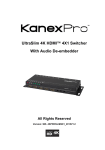
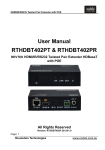
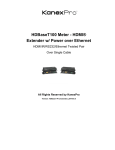
1
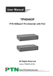
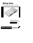
User Manual DVM-HDBT-RXLPOC DVM HDBaseT Receiver 70m PowerOverCable All Rights Reserved Version: DVM-HDBT-RXLPOC_2015V1.0 HDBaseT Receiver with PoC Preface Read this user manual carefully before using this product. Pictures shown in this manual is for reference only, different model and specifications are subject to real product. This manual is only for operation instruction only, not for any maintenance usage. The functions described in this version are updated till March 2015. Any changes of functions and parameters since then will be informed separately. Please refer to the dealers for the latest details. All product function is valid till 2015-6-10. Trademarks Product model and logo are trademarks. Any other trademarks mentioned in this manual are acknowledged as the properties of the trademark owner. No part of this publication may be copied or reproduced without prior written consent. FCC Statement This equipment generates, uses and can radiate radio frequency energy and, if not installed and used in accordance with the instructions, may cause harmful interference to radio communications. It has been tested and found to comply with the limits for a Class B digital device, pursuant to part 15 of the FCC Rules. These limits are designed to provide reasonable protection against harmful interference in a commercial installation. Operation of this equipment in a residential area is likely to cause interference, in which case the user at their own expense will be required to take whatever measures may be necessary to correct the interference Any changes or modifications not expressly approved by the manufacture would void the user’s authority to operate the equipment. HDBaseT Receiver with PoC SAFETY PRECAUTIONS To insure the best from the product, please read all instructions carefully before using the device. Save this manual for further reference. Unpack the equipment carefully and save the original box and packing material for possible future shipment Follow basic safety precautions to reduce the risk of fire, electrical shock and injury to persons. Do not dismantle the housing or modify the module. It may result in electrical shock or burn. Using supplies or parts not meeting the products’ specifications may cause damage, deterioration or malfunction. Refer all servicing to qualified service personnel. To prevent fire or shock hazard, do not expose the unit to rain, moisture or install this product near water. Do not put any heavy items on the extension cable in case of extrusion. Do not remove the housing of the device as opening or removing housing may expose you to dangerous voltage or other hazards. Install the device in a place with fine ventilation to avoid damage caused by overheat. Keep the module away from liquids. Spillage into the housing may result in fire, electrical shock, or equipment damage. If an object or liquid falls or spills on to the housing, unplug the module immediately. Do not twist or pull by force ends of the optical cable. It can cause malfunction. Do not use liquid or aerosol cleaners to clean this unit. Always unplug the power to the device before cleaning. Unplug the power cord when left unused for a long period of time. Information on disposal for scrapped devices: do not burn or mix with general household waste, please treat them as normal electrical wastes. HDBaseT Receiver with PoC Contents 1. Introduction .................................................................................................................1 1.1 Introduction to HDBaseT Receiver .................................................................... 1 1.2 Features ............................................................................................................ 1 1.3 Package List ...................................................................................................... 1 2. Product Appearance ...................................................................................................2 3. System Connection .....................................................................................................3 3.1 Usage Precautions ............................................................................................ 3 3.2 System Diagram ................................................................................................ 3 3.3 Connection Procedure ....................................................................................... 3 3.4 Application ......................................................................................................... 4 3.5 Twisted Pair Cable Connection .......................................................................... 4 4. Specification ...............................................................................................................5 5. Panel Drawing ............................................................................................................6 6. Troubleshooting & Maintenance .................................................................................6 7. After-sales Service ......................................................................................................7 HDBaseT Receiver with PoC 1. Introduction 1.1 Introduction to HDBaseT Receiver HDBaseT Receiver adopts HDBaseT technology to deliver HDMI signal, two-way IR control, bi-directional RS232 data up to 70m with perfect quality. It also supports CEC and PoC. It works well with HDBT transmitters or other devices boasting HDBT OUT port. 1.2 Features Support Full HD: Delivers resolutions including 800x600@60Hz, 1024x768@Hz, 1280x720@60Hz, 1280x1024@60Hz, 1366x768@60Hz, 1600x1200@60Hz, 1920x1080@60Hz, 1920x1200@60Hz, 3D, 4K×2K Max transmission distance is up to 70 meters over single CAT5e/CAT6 cable. High Bandwidth: 10.2Gps. HDTV Compatible, use HDMI 1.4 and HDCP compliant. Support PoC & CEC. Connect with a displayer to transmit EDID and HPD signals constantly by using a CAT5e cable. Use HDBaseT technology. Bi-directional RS232/IR control. LED indicators show work status. Wall/table-mountable aluminium enclosure, PT case design. 1.3 Package List 1 x HDBaseT Receiver 2 x Mounting brackets 4 x Screws 1 x RS232 cable 4 x Plastic cushions 1 x User Manual Notes: Please confirm if the product and the accessories are all included, if not, please contact with the dealers. 1 HDBaseT Receiver with PoC 2. Product Appearance No. Name Description ① ON ② LINK Twisted Pair link status indicator, illuminates when the port has a connection ③ IN HDCP compliance indicator, illuminate green when the connected device supports HDCP; blink green when the connected device does not support HDCP ④ POWER LED ⑤ HDBT IN ⑥ HDMI OUT ⑦ IR IN ⑧ IR OUT Connect with IR transmitter, the sent IR signal are received by other devices (e.g. HDBaseT Transmitter) ⑨ RS232 Serial port, 3-pin captive screw connector, connects with the control terminal, supports bi-directional RS232 control ⑩ DC 24V Connect with power supply (not necessary if the other device s connects with power and supports PoC) Working status indicator, blink when the device is working Illuminate red when powered on Connect to the HDBT OUT port of other devices (e.g. HDBaseT Transmitter) with a CAT5e cable, support bi-directional PoC Connect to HDMI display Connect with IR receiver, the IR signal received from this port can only send out via other devices (e.g. HDBaseT Transmitter) Pictures shown in this manual are for reference only. 2 HDBaseT Receiver with PoC 3. System Connection 3.1 Usage Precautions 1) System should be installed in a clean environment and has a prop temperature and humidity. 2) All of the power switches, plugs, sockets and power cords should be insulated and safety. 3) All devices should be connected before power on. 3.2 System Diagram The following diagram illustrates typical input and output connections that can be utilized with HDBaseT Receiver: Receiver Transmitter INPUT Rs232 control panel IR Remote HDMI HDMI DVD CAT5e Projector 3.3 Connection Procedure (Exampled by connecting to HDBaseT Transmitter) Step1. Connect HDMI source (such as Blue-ray DVD) to HDMI IN port of HDBaseT Transmitter with HDMI cable. Step2. Connect HDBT OUT port of HDBaseT Transmitter to HDBT IN port of HDBaseT Receiver through a CAT5e/CAT6 cable. Step3. Connect a HDMI displayer (such as HDTV) to HDMI OUT port of HDBaseT Receiver with HDMI cable. Step4. Both HDBaseT Transmitter and HDBaseT Receiver have IR IN and OUT. When one end is used as an IR receiver, the other end will be used as an IR transmitter. For example: When “IR IN” of HDBaseT Transmitter connects with an IR receiver, the IR transmitter must be connected to “IR OUT” of HDBaseT Receiver. Step5. Connect the RS232 port of the devices to be controlled and the receiver or the transmitter. Step6. Connect with DC 24V power adaptor(s) (One is sufficient as the other end can be 3 HDBaseT Receiver with PoC energized with PoC function). 3.4 Application HDBaseT Receiver has a good application in various occasions, such as computer realm, monitoring, big screen displaying, meeting room, education and bank & securities institution etc. 3.5 Twisted Pair Cable Connection The twisted pair used in this extender MUST be a straight-through cable. The connectors can be T568A or T568B, but both sides must be the same. TIA/EIA T568A TIA/EIA T568B Pin Cable color Pin 1 green white 1 orange white 2 green 2 orange 3 orange white 3 green white 4 blue 4 blue 5 blue white 5 blue white 6 orange 6 green 7 brown white 7 brown white 8 brown 8 brown 1st Group 2nd Group 3rd Group 4th Group 4--5 3--6 1--2 7--8 1st Group 2nd Group 3rd Group 4th Group Cable color 4--5 1--2 3--6 7--8 Note: To make a better transmission, cable connectors MUST be metallic, the shielded layer of cable MUST be connected to the connector’s metal shell. 4 HDBaseT Receiver with PoC 4. Specification Input& Output Input 1 IR (3.5mm mini jack) 1 HDBT (RJ-45) 1 RS232 (3-pin pluggable terminal block) 1 HDMI (HDMI female) Output 1 IR (3.5mm mini jack) 1RS232 (3-pin pluggable terminal block) Video Signal HDMI1.4 Audio Digital audio, transmit through HDMI audio Transmission Mode HDBaseT General Resolution 800x600@60Hz, 1024x768@Hz, 1280x720@60Hz, 1280x1024@60Hz, 1366x768@60Hz, 1600x1200@60Hz, 1920x1080@60Hz, 1920x1200@60Hz, 3D, 4K×2K Transmission Distance ≤70M SNR >70dB@ 100MHz-100M Bandwidth 10.2Gbps THD <0.005%@1KHz HDMI Standard Support HDMI1.4& HDCP Impedance 75Ω Temperature -10 ~ +40℃ Humidity 10% ~ 90% Power Supply Input: 100VAC~240VAC, 50/60Hz; Output: DC 24V, 1.25A Power Consumption 9.6W Dimension (W*H*D) 110 x 77x 30 mm Weight 0.5Kg All nominal levels are at ±10%. 5 HDBaseT Receiver with PoC 5. Panel Drawing 14.00 mm 110.03 mm 30.00 mm HDBaseT Technology HDCP Compliant 4K x 2K Support 77.00 mm 60m with PoC 50.00 mm HDBaseT Lite Receiver/PoC PoC Tx ON LINK Rx OUT HDBT IN HDMI OUT IR IN IR OUT RS232 6. Troubleshooting & Maintenance Problems Poor quality of output images No output image Causes Solutions Incorrect setting on the display Check the display’s setting Bad quality of the cable Try another high quality connection cable No signal at the input/ output end Check with oscilloscope or multimeter if there is any signal at the input / output end. Fail or loose connection The extender is broken Cannot control the device by control device (e.g. a PC) through RS232 port Static becomes stronger when connecting the video connectors Cannot control the device by RS232 / IR Wrong RS232 communication parameters Make sure the connection is good Send it to authorized dealer for repairing. Make sure the RS232 communication parameters are correct. The device has already been broken Send it to authorized dealer for repairing. Bad grounding Check the grounding and make sure it is connected well. The device has already been broken Send it to authorized dealer for repairing. 6 HDBaseT Receiver with PoC If your problem persists after following the above troubleshooting steps, seek further help from authorized dealer or our technical support. 7. After-sales Service If there appear some problems when running the device, please check and deal with the problems reference to this user manual. 1) Product Limited Warranty: We warrant that our products will be free from defects in materials and workmanship for three years, which starts from the first day the product leaves warehouse (check the SN mark on the product). Proof of purchase in the form of a bill of sale or receipted invoice must be presented to obtain warranty service. 2) What the warranty does not cover: Warranty expiration. Factory applied serial number has been altered or removed from the product. Damage, deterioration or malfunction caused by: Normal wear and tear Use of supplies or parts not meeting our specifications No certificate or invoice as the proof of warranty. The product model showed on the warranty card does not match with the model of the product for repairing or had been altered. Damage caused by force majeure. Servicing not authorized Other causes which does not relate to a product defect Delivery, installation or labor charges for installation or setup of the product 3) Technical Support: Email to our after-sales department or make a call, please inform us the following information about your cases. Product version and name. Detailed failure situations. The formation of the cases. Remarks: For any questions or problems, please try to get help from your local distributor. 7 SOMMER CABLE GmbH Humboldtstraße 32-36 75334 Straubenhardt / Germany Telefon: Support Tel: +49 (0)7082-49133-0 +49 (0)7082-49133-10 Fax: +49 (0)7082-49133-11 E-Mail: [email protected] Internet: www.sommercable.com