1
5. Typical Application Diagram
Setting Ranges
Undervoltage
Time delay for undervoltage
Overvoltage
Time delay for overvoltage
Unbalance
Time delay for unbalance
Phase loss
Phase sequence
Start time delay
(OPTIONAL)
1
2
3
4
R1
8
5
7
6
R2
9
10
11
12
14
13
MU250 3-Phase Voltage Relay User's Guide V2
7. Technical Data
L1
L2
L3
N
: Off, 1% – 25%
: 0.1s – 30s
: Off, 1% – 20%
: 0.1s – 30s
: Off, 3% – 20%
: 0.5s – 30s
: Fixed time <0.5s
: Fixed time <0.5s
: 0s – 999s
Brief Overview
a
h
g
b
Neutral connection is optional when Phase
option is set to L-L. Neutral connection is
required when Phase option is set to L-N. (refer
to Setting b - Phase)
6. Case Dimensions
71 mm
70 mm
20 mm
85 mm
45 mm
Front
Side
20 mm
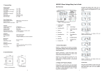
Figure 6: Case Dimensions
30 mm 20 mm 20 mm
U 12
c
MU250
Figure 5
The Data LED showing value. Press “UP” or
“DOWN” to scroll through the parameters as
shown in Figure 2 and 3 (depends on L-L or L-N
setting).
Power Supply Input
Phase to phase voltage
MU250-415V
MU250-220V
MU250-110V
: 380V(-25%)-415V(+20%) AC
: 220V(-25%)-240V(+20%) AC
: 100V(-25%)-120V(+20%) AC
Supply frequency
Maximum power consumption
: 45Hz to 65Hz
: 3VA
Contacts
Contact arrangement
Contact rating
Contact material
Operating time
Expected electrical life
Expected mechanical life
Indicators
Auxiliary supply
Pickup indicator
Trip
Mechanical
Mounting
Approximate weight
Accuracy
Protection thresholds
Time delay
Measurements
d
f
: Change-over
: 5A, 250V AC(cosϕ=1)
: Silver alloy
: 15 ms max
: 100,000 operations at rated current
: 5 x 10⁶ operations
: Green LED indicator
: Red LED indicator
: 7-segment display and red LED
indicators
e
U 23
Figure 1: Front panel overview
a – Auxiliary power
supply LED
Symbols
U<<
- Undervoltage
t<<
- Undervoltage time
delay
d – Down key
U>>
- Overvoltage
e – Reset/Mode key
t>>
- Overvoltage time
delay
b – Trip/Pickup LED
c – Up key
f – Test key
Frequency
Figure 2: Display for L-L setting. 415V and
50.0Hz shown as example
- Unbalance/phase
g – Function LED
h – Data LED
U 31
t
- Unbalance time
delay
U 1N
: Din rail mounted
: 0.31kg
: ±3%
: 0-0.5s, ± 15% with a minimum
of 40ms
: 0.6s and above, ± 3%
: ± 3%
1. General Description
U 2N
MU250 is a voltage relay that combines overvoltage,
undervoltage, unbalance, phase loss, phase sequence
and delay start functions. It can be connected with or
without neutral wire.
U 3N
MU250 incorporates a 4-digit LED display which
allows direct numerical readout of set values, actual
measured value and system indication.
MU250 has 2 relay outputs (R1 and R2). R1 is
energized under normal operating condition. R2 can
be configured as normally energized or de-energized.
Both R1 and R2 can be assigned to operate
separately by various tripping elements.
Frequency
Figure 3: Display for L-N setting. 240V and
50.0Hz shown as example
a) Auto Scroll
2. Voltage and Frequency Display
4
During power up, when the relay is not under tripping
condition, the display will show voltage and frequency
reading. The Function LED indicates which line/phase
of voltage is being displayed or shows 'F' when
frequency is being displayed.
Auto scroll let the display to scroll to the next
available parameter every 10 seconds. To toggle
auto scroll mode, press "UP" and "DOWN"
simultaneously.
1
3. Settings
Voltage/Frequency Display
a) Setting Display
Trip History
When the relay is not under tripping condition,
pressing “RESET/MODE” can scroll through various
settings. Function LED showing number or alphabet to
indicate which setting is being view as shown in
Figure 4. Table 1 gives description of each setting.
Tip: To quickly jump back to voltage display during
setting display, press and hold “RESET/MODE” for
more than 1.5 seconds.
4. Trip
Undervoltage pickup occurs when any line to line or
line to neutral voltage is less than [nominal voltage U<< %], relay trips when delay time is elapsed.
a) Trip Display
1 U<< Undervoltage %
d) Overvoltage
2 t << Undervoltage time delay
3 U>> Overvoltage %
Overvoltage pickup occurs when any line to line or line
to neutral voltage is more than [nominal voltage + U>>
%], relay trips when delay time is elapsed.
4 t >> Overvoltage time delay
e) Unbalance
b) Programming Setting
5
Unbalance %
Step 1: Press “RESET/MODE” until the Function LED
shows the required setting.
6 t
Unbalance time delay
A tstart Start time delay
Step 2: Press “UP” and “DOWN” simultaneously to
enter programming mode.
The Function LED blinks to indicates the relay is in
programming mode.
c) Undervoltage
b Phase
c Nominal voltage
During pickup, Trip/Pickup LED blinks. During tripping
condition, Trip/Pickup LED on. Function LED and Data
LED blinks with trip source as shown below:
Function
LED
Unbalance is calculated as:
(Vmax-Vmin)/Vmin X 100%
Where Vmax is the maximum voltage among the 3
voltages. Vmin is the minimum voltage among the 3
voltages.
Unbalance pickup occurs when unbalance is more
than set %, relay trips when delay time is elapsed.
Data LED
Description
1
trip voltage
Undervoltage trip
3
trip voltage
Overvoltage trip
5
Ub
Unbalance trip
5
PL
Phase loss trip
5
PS
Phase sequence trip
t
EST
Test
Table 3: Trip display
b) Trip Reset
Phase Sequence trip occurs when the phase
sequence in any 2 or all of the lines are reversed.
Step 4: To save the selected value, press “UP” and
“DOWN” simultaneously again.
It will exit the
programming mode with the Data LED displaying the
newly set value.
E Relay R2 function
Phase Loss trip occurs when any voltage is less than
70% of nominal.
During tripping condition, press “RESET/MODE” to
reset the relay, the relay will reset if condition
permits. If relay is set to Auto reset, the relay will
reset automatically if the condition is 5% below trip
condition.
F Relay R2 type
f) Starting Delay
c) Trip Test
To exit programming mode without saving the selected
setting, press “RESET/MODE” once.
g Auto/Manual reset
Starting delay is the delay time for R1 to turn on during
power up under normal condition.
Trip test is used to simulate a tripping condition.
Press “TEST” button and hold for 1.5s, trip LED
blinks. After 1.5 seconds, “tESt” will blink, R1 off and
R2 will operate by relay R2 type. Press
“RESET/MODE” to reset.
Step 3: Press “UP” or “DOWN” to select the desired
value.
d Relay R1 function
Figure 4: Display mode when pressing
Reset/Mode
Setting
Function
1
U<< Undervoltage
Setting Range
off, 1-25 %
Description
Undervoltage % from nominal voltage
2
t<< Undervoltage delay 0.1-30 s
Time delay for undervoltage
3
U>> Overvoltage
off, 1-20 %
Overvoltage % from nominal voltage
4
t>> Overvoltage delay
0.1-30 s
Time delay for overvoltage
Unbalance
off, 3-20%
Unbalance %
Unbalance delay
0.5-30 s
Unbalance time delay
5
6
t
A
t start Starting delay
0-999 s
On time delay of R1 during power up
b
Phase
L-L, L-N
L-L: Display and uses Line to Line voltage
L-N: Display and uses Line to Neutral
voltage
Nominal voltage. Value depends on L-L or
L-N setting
*Refer to Table 2
c
Nominal Voltage
d
Relay R1 function
380, 400, 415 V or
220, 230, 240 V
0-7
E
Relay R2 function
0-7
*Refer to Table 2
F
Relay R2 type
0-1
0: Normally de-energized
1: Normally energized
g
Auto/Manual resetting
0=auto, 1=manual
auto: auto reset when trip condition clear
manual: press "RESET/MODE" to reset
g) Relay Function Selection
During tripping, output contact relay R1 or R2 will be
de-energized/energized if the related tripping element is
activated.
The setting is shown below:
Code
Phase OV
d) Trip History Display
During Voltage and frequency display, Press
“RESET/MODE” button to jump to Trip History
Display. Display shows the previous trip status with
a 'dot' blinking at Function LED. To clear trip history,
press "UP" and "DOWN" simultaneously.
UV Code : Displays on Data LED
0
0
0
0
1
0
0
1
2
0
1
0
3
0
1
1
4
1
0
0
5
1
0
1
6
1
1
0
7
1
1
1
Phase: Unbalance, Phase Loss
and Phase Sequence
OV : Overvoltage
UV : Undervoltage
e) Trip Bypass Mode
To disable tripping due to incorrect setting, press
“RESET/MODE” and “TEST” simultaneously during
power up. The Trip LED slow blink to indicate Trip
Bypass Mode. Go into programming mode to correct
the setting. Power off and on to reset the relay. The
relay will return to normal if no button is pressed for
longer than 2 minutes.
0= De-activated
1= Activated
Table 2: Relay function selection
Table 1: Description of functions
2
3