1
AIMING and SUSPENDING INSTRUCTIONS
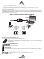
PREDICTION: EASE Focus 2
To aim correctly a complete system we suggests to use always the Aiming Software - EASE Focus 2:
The EASE Focus 2 Aiming Software is a 3D Acoustic Modelling Software that serves for the configuration
and modelling of Line Arrays and conventional speakers close to reality. It only considers the direct
field, created by the complex addition of the sound contributions of the individual loudspeakers or
array components.
The design of EASE Focus is targeted at the end user. It allows the easy and quick prediction of the array
performance in a given venue. The scientific base of EASE Focus stems from EASE, the professional
electro- and room acoustic simulation software developed by AFMG Technologies GmbH. It is based on
the EASE GLL loudspeaker data file required for its use: AXIOM_AX Series_v2_0.GLL, please note that the version must be 2.0 or more. The GLL
file contains the data that defines the Line Array with regard to its possible configurations as well as to its geometrical and acoustical properties.
For detailed explanation of how to use the software and how to obtain a correct aiming refer to EASE Focus documentation and other on-line
manuals (http://focus.afmg.eu/index.php/fc-software-en.html).
WARNING! CAREFULLY READ THE FOLLOWING INSTRUCTIONS AND CONDITION OF USE:
• This loudspeaker is designed exclusively for Professional audio applications. The product must be installed by qualified personal only.
• Proel strongly recommends that this loudspeaker cabinet be suspended taking into consideration all current National, Federal, State and
Local regulations. Please contact the manufacturer for further information.
• Proel do not accept any liability for damage caused to third parties due to improper installation, lack of maintenance, tampering or
improper use of this product, including disregard of acceptable and applicable safety standards.
• During assembly pay attention to the possible risk of crushing. Wear suitable protective clothing. Observe all instructions given on the
rigging components and the loudspeaker cabinets. When chain hoists are in operation ensure that there is nobody directly underneath or
in the vicinity of the load. Do not under any circumstances climb on the array.
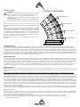
KPTSW215 Fly Bar and accessories
The AX2065 Systems are built to allow the suspension of array with variable shape and dimensions. Thanks to a suspension mechanism designed
to be functional, flexible and safe, each system must be suspended or stacked using the KPTSW215 fly bar. The loudspeakers are linked together
in a column using a series of couplers integrated in the frame of each enclosure. Each system is set up properly both acoustically and mechanically
only using the aiming software.
Coupling system in the front does not require any adjustment: using two locking pins, each loudspeaker box is fixed to the previous. The slotted
bar in the back is inserted in a U-shaped frame which features a series of numbered holes. Sliding the slotted bar in the U-shaped frame of the
next loudspeaker and inserting a locking pin in one of the numbered holes, it is possible to adjust the relative splay angle between two adjacent
loudspeakers in the array column.
KPTSW215 fly bar maximum capacity is 540 Kg (1190 lbs) with the 0° angle. It can support, with a safety factor of 10:1, up to:
• 8 AX2065A + 8 AX2065P (flybar from 0° to 10°)
KPTSW215 FLY BAR ASSEMBLY SEQUENCE
• 12 AX2065A (flybar from 0 to 10°)
• 2 SW215AF + 4 AX2065A + 4 AX2065P (flybar at 0°)
• 2 SW215AF + 8 AX2065A (flybar at 0°)
• 6 SW215AF (flybar from 0° to 5°)
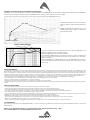
Follow the sequence in the figure for fixing the fly bar at the first box. Usually
this is the first step before lifting up the system. Be careful to insert properly
all the locking pins (1)(2) and (3)(4) then the shackle (5) in the right holes as
5
specified by the aiming software.
1
When lifting the system always proceed gradually step by step, paying
1
2
attention to secure the fly bar to the box (and the box to the other boxes)
before pulling up the system: this makes easier to insert properly the locking
KPTSW215 FLY BAR AND ACCESSORIES
STRAIGHT SHACKLE 16mm
M10 FOOT FOR
STACKED INSTALLATION
(OPTIONAL)
3
2
4
IDENTIFICATION AND
DATA LABEL
FRONT BOX
PIN ATTACHMENT
SUSPEND HOLE
INDICATOR
SUSPEND HOLES
REAR BOX
PIN ATTACHMENT
FRONT BOX
PIN ATTACHMENT
pins. Also when the system is released down, unlock gradually the
pins.
During the lifting be very careful to not let the cables enter the space
between one enclosure and the other, as their compression could
cut them.