1
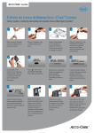
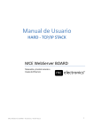
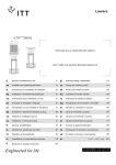
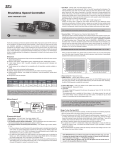
INLINE MIXED-FLOW FANS
VENTS TT SERIES
USER'S MANUAL
www.ventilation-system.com
2011
Read this manual carefully before installation and commissioning of the unit.
!
READ THE INSTRUCTIONS CAREFULLY TO REDUCE THE RISK OF FIRE, ELECTRIC SHOCK OR INJURY.
WARNING Compliance with the manual requirements ensures reliable fan operation throughout the entire service life.
This user's manual contains technical and operating logic
description, mounting requirements, servicing and
maintenance guidelines for the inline mixed-flow fans TT
designed for supply or exhaust ventilation of premises
heated during winter time.
The fans are designed both for horizontal or vertical
installation and are suitable for individual installation of one
unit (fig. 2) or two or more units mounted in series or
in parallel (fig.3).
The mounting kit components are delivered upon request.
An air duct at least 1 meter long must be connected to the
intake flange in case of horizontal fan mounting; a cowl
must be installed in case of vertical mounting.
The fans are made of plastic.
The delivery set includes:
1. Fan - 1 pce;
2. Screws and dowels - 4 pcs;
3. User's manual;
4. Packing box.
The intake flange must always be connected to an air duct.
Mounting sequence is shown in fig. 4-11.
The wiring diagrams are shown is fig. 12-16.
The fans are powered by AC 220-240V, 50-60 Hz single phase
current and designed for continuous operation always
connected to the electric mains.
Ingress protection rating IP X4.
Designations:
QF - automatic circuit breaker (fig. 1);
S - external switch (fig. 1);
X - input terminal.
The fans are designed for operation at the temperature
range from +0°Ñ up to +40°Ñ. The air temperature in the
ventilation system must not exceed +45°Ñ.
Automatic circuit breaker
designation
Automatic circuit breaker
QF
Store the fan in manufacturer’s packaging in a ventilated
room at temperatures between +5°C and +40°C and relative
humidity not more than 80% at +25°C.
The fans are suitable for connection to
100, 125, 150, 160, 200, 250, 315 mm air ducts.
External switch
designation
The "S" index fan modifications are equipped with
a high-power motor.
External switch
S
Air flow direction should match the direction of the arrow
on the fan casing.
1
Due to the constant improvements the design of some models
may slightly differ from those described in this manual.
2
Any electric connections, adjustment, servicing and repair
works are allowed only after the unit is disconnected from
power mains.
Mounting and maintenance are allowed for duly qualified
electricians with valid electrical work permit.
The single-phase power grid must comply with the acting
local electrical norms and standards. The fixed electrical
wiring must be equipped with an automatic circuit breaker.
The fan must be connected to the power grid through the
automatic circuit breaker QF. The gap between the breaker
contacts on all poles must be not less than 3 mm.
The overcurrent value shall be equal to the fan current
consumption and is indicated on the fan rating plate.
Before installation check the fan for any visible damages
of impeller and casing. The casing internals must be free
of any foreign objects which can damage the impeller blades.
Misuse of the device or any unauthorized modifications are
not allowed.
The unit is not to be used by children and persons with
reduced physical, mental or sensory capacities, without
proper practical experience or expertise, unless they are
controlled or instructed on the unit operation by the person(s)
responsible for their safety. Do not leave the children
unattended to avoid their playing with the device.
Take steps to prevent ingress of smoke, carbon monoxide
and other combustion products into the room through open
chimney flues or other fire-protection devices.
Sufficient air supply must be provided for proper combustion
and exhaust of gases through the flue (chimney) of fuel
burning equipment to prevent backdrafting.
The transported air must not contain any dust or other solid
impurities, sticky substances or fibrous materials.
Do not use the fan in the environment containing hazardous
or explosive materials and vapors, i.e. spirits, gasoline,
insecticides, etc.
Do not close or block the intake and exhaust vents not to
disturb the natural air passage.
Do not sit or put objects on the unit.
This product must be disposed separately
after deadline scheduling.
Do not throw out this product
with unsorted city waste.
3
WARRANTY
While purchasing the unit the customer accepts the following
warranty terms:
Manufacturer hereby guarantees normal operation of the unit
for 60 months from the date of resale, subject to the
compliance with transport, storage, mounting and operation
rules. In case of warranty service need submit this user's
manual with filled manufacturing date and sales receipt or
any other ownership confirmation. The unit modification must
match the model stated by the user's manual.
In case of non-submittion of the sales receipt or any other
ownership confirmation and confirmation of the sales date,
warranty period is calculated from the production date.
Failure to submit the above documents may result in refuse
for free servicing of faulty equipment.
All the units and components belonging to the faulty unit and
replaced within the warranty period shall be covered by the
previous warranty period and general warranty conditions.
Thus the warranty period is not extended for the replaced fan
components.
In case of failure due to faulty equipment during warranty
period, the consumer has the right to exchange it.
The accessories operated together with the unit, both
included and not included into the delivery list as well as other
equipment operating jointly with the unit shall not be covered
by the warranty. No warranty for compatibility of the fans with
other producers' goods.
Only manufacturing defects are covered by the warranty terms.
All the defects and faults resulting from mechanical effect
during operation process or natural wear-and-tear shall not
be covered by the warranty conditions.
The malfunctions caused by violence of operation, servicing
and maintenance guidelines either by Customer or third
parties or caused by unauthorized design modifications shall
not be covered by warranty.
NO LIABILITY FOR THE RELATED DAMAGES:
The manufacturer is not responsible for any mechanical or
physical damages resulting from the manual requirements
violence, the unit misuse or gross mechanical effect.
The indirect damages such as re-installation or re-connection
of the unit, direct or indirect losses etc related to the unit
replacement shall not be indemnified. Mounting/dismantling,
connection/disconnection and regulation of the unit shall not
be covered by the warranty. The contractor in charge for
quality of mounting, electric mounting and adjustment works
shall be responsible for the warranty thereof.
In any case the indemnity amount shall not exceed the actually
paid value for the defective unit price.
min 1 ì
2
3
4
MOUNTING
SEQUENCE
QF
4
5
6
7
8
9
10
11
5
WIRING DIAGRAM FOR TT 100, TT 125 fan modifications
X
QF
L
L
~
N
N
14
12
WIRING DIAGRAM FOR TT 125S, TT 150, TT 160 fan modifications
X
QF
L
L
~
N
N
13
WIRING DIAGRAM FOR TT 200, TT 250, TT 315 fan modifications
X
QF
L
L
~
N
N
14
WIRING DIAGRAM FOR TT 100T, TT125T, TT125ST, TT150T, TT160T, TT200T, TT250T, TT315T
18
X
QF
N
~
L
16
15
6
N
L
FAN CONNECTION WITHOUT INTEGRATED TIMER
1. Power the unit off by turning the automatic circuit breaker QF to OFF position.
2. Release the fixing screws of the terminal block and remove the cover (fig. 18).
3. Release the retaining clip screws and remove the retaining clip (fig. 19).
4. Route the electric cable to the terminal block through the sealed lead-in and fix the cable with a retaining clip and screws (fig. 20).
5. Select the fan operation mode (maximum speed, medium speed, low speed or speed switch with external speed switch).
Connect the cables to the input fan terminal block in compliance with the matching wiring diagram and terminal designation
inside the terminal box.
6. Install the terminal box cover and fix it with self-tapping screws (fig. 21).
7. Switch the fan on by turning the automatic circuit breaker to ON position (fig. 22).
The fan starts running at required speed in case of correct electrical connection.
If the fan does not operate, troubleshoot the malfunction.
QF
17
18
19
20
21
22
7
FAN CONNECTION WITH INTEGRATED TIMER
1. Follow all the described above actions, clause 1-4 for fan connection without integrated timer.
2. Connect the cables to the input fan terminal block in compliance with the matching wiring diagram and terminal
designation inside the terminal box.
3. Adjust the timer operating time by means of rotating the potentiometer adjusting screws (fig. 23) clockwise to
increase the delay time or counter-clockwise to decrease it.
4. Follow the described above actions, clause 6-7 for fan connection without integrated timer.
Õ
2 min
+
30 min
23
8
FAN MODIFICATION WITH POWER CORD
The "V" index fan modifications are equipped with a three speed switch.
The "RV" index fan modification is equipped with a power cord with various plug types and integrated three speed switch.
This fan modifiation does not require any mounting operations for connection.
The built-in speed switch provides three fan air capacity modes:
0 - fan is off
I - low speed operation
II - maximum speed operation
The"V" and "RV" fan modifications do not include timer modification.
MIN
MAX
STOP
24
9
FANS WITH TEMPERATURE AND SPEED CONTROLLER MODULE TSC
The TT U fans (fig. 25) enable automatic impeller speed (air flow) control depending on the air temperature in the duct.
The "n" index models are equipped with a remote temperature sensor on a 4 m extension cable.
All the fan models with TSC module are equipped with a power cable.
The front panel has the following control knobs:
- pre-set impeller speed;
- thermostat operating threshold;
The yellow light indicator on the front panel shows thermostat operation.
Timer Operation Algorithm
Set the desired thermostat temperature (operating threshold) by turning the thermostat control knob.
Set the desired impeller speed (air flow) by turning the impeller speed control knob.
On reaching the pre-set air temperature and exceeding the thermostat operating threshold the fan motor switches to the
maximum speed (maximum air flow).
The fan motor switches to the pre-set speed as the temperature drops below the pre-set thermostat operating threshold.
The switching delay function is provided to prevent frequent fan speed changes due to crossing the temperature threshold,
especially if the operating temperature is equal to the thermostat threshold value.
The switch-off delay operating logic has two versions:
TT U (Temperature sensor delay algorithm)
On exceeding the pre-set temperature 2°C above the thermostat operating threshold the fan motor switches to the
maximum speed. The fan motor reverts to the pre-set speed as soon as the duct temperature drops 2°C below the thermostat
operating threshold. This algorithm is used to maintain the desired temperature up to within 2°C.
The fan speed changes are rare in this case.
TT U1 (Timer delay algorithm)
On reaching the pre-set air temperature the motor switches to higher (maximum) speed and the delay timer starts the
5-minute countdown. The fan motor reverts to the previous speed not earlier than 5 minutes after the duct air temperature
drops below the thermostat pre-set threshold. This algorithm is used to maintain the desired air temperature precisely.
In this mode the fan motor changes its speed more frequent as compared to the temperature sensor delay mode but in any
case the switching cycle does not exceed 5 minutes.
pre-set impeller
speed control knob
electronic thermostat
operating threshold control knob
tC
24
23
22
21
min
25
10
max
20°C
25
26
27
28
29
30°C
MAINTENANCE
Maintenance (fig. 26-30) means periodic cleaning of the surfaces from dust and dirt.
The impeller blades require thorough cleaning every six months.
To clean the impeller blades detach the clamps, remove the casing and wipe the blades with warm water and
mild detergent solution.
Avoid water dripping on the motor while cleaning the blades (fig. 31).
MALFUNCTIONS AND TROUBLESHOOTING
1. Fan does not get started - broken electric circuit.
Check the cable connection to the terminal block.
2. Excessive noise during the fan operation - foreign objects inside the fan casing.
Dismantle the fan (fig. 26-29) and remove foreign objects.
3. Excessive vibration during the fan operation - loose fan connection to the wall or the wall is not rigid enough.
Check the fan connection.
26
27
28
29
30
31
11
ACCEPTANCE INFORMATION
Fan is ready for using.
TT 100
TT 100T
TT 125
TT 125T
TT 125S
TT 125ST
TT 150
TT 150T
TT 160
TT 160T
TT 200
TT 200T
TT 250
TT 250T
TT 315
TT 315T
TT 100V
TT 100RV
TT 125V
TT 125RV
TT 125SV
TT 125SRV
TT 150V
TT 150RV
TT 160V
TT 160RV
TT 200V
TT 200RV
TT 250V
TT 250RV
TT 315V
TT 315RV
Acceptance stamp
Date of production
Sold
TT 100U
(name of trade enterprise and stamp of the shop)
TT 125U
TT 125SU
TT 150U
TT 160U
1
n
Date of sale
TT 200U
TT 250U
TT 315U
www.ventilation-system.com
V10(ÒÒ-1)EN-06