1
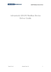
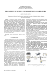
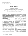
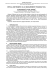
11th IMEKO TC-4 Symp. - Trends in Electrical Measurement and Instrumentation - September 13-14, 2001 - Lisbon, Portugal
INDUSTRIAL WATER LEVEL MEASUREMENT AND CONTROL SYSTEM
BASED ON VIRTUAL INSTRUMENT TECHNOLOGY
Tianshu Huang(IEEE member)(1), Zheng Zhang(2) ,Qingzhen Ren(3), Jidong Xiang(4)
(1)
(2)
(3)
(4)
Department of Electronic Information, Wuhan University, Wuhan, 430072, P.R.China
Tel: 86-27-67803897, Fax: 86-27-67803410, e-mail: [email protected]
Department of Electronic Information, Wuhan University, Wuhan, 430072, P.R.China
Tel: 86-27-67803896, Fax: 86-27-67802125, e-mail: [email protected]
Department of Electronic Information, Wuhan University, Wuhan, 430072, P.R.China
Tel: 86-27-67803897, Fax: 86-27-67803410, e-mail: [email protected]
Department of Electronic Information, Wuhan University, Wuhan, 430072, P.R.China
Tel: 86-27-67803896, Fax: 86-27-67802125, e-mail: [email protected]
Abstract This
paper
discusses
the
design
and
implementation of a new industrial water level measurement
and control system. Virtual Instrument technology is
employed to construct the software and hardware
framework. The modularized system features high flexibility
and expandability. The system provides with parameter
display, data testing, alarming, storage and printing. The
system is opening and compatible.
Fig.1 is the system constructed with virtual instrument
technology. It is used for measuring temperature, pressure,
flux and signal of valves. PLC communicates with the upper
host computer in series communication.
Host PC
Printer
Keywords - Virtual instrument, communication, water level,
control
ADAM
5510
ADAM
5510
1. INTRODUCTION
Temp.
Flux
Pressure
Valve
Temp.
Flux
Fig.1 System Construction
System
uses
virtual
instrument
graphics
programmable software ---- LabVIEW. Based on virtual
instrument technology, system may be described as
following,
(1) Instrument Module: It is hardware level and is directly
faced to object. It is the base of water level control system. It
implements functions of data acquisition, adjustable control
etc. Input message of ADAM5510 module is faced to
transducers’ signals, such as flux, pressure and water level
etc.
Instrument Interface: RS-232 is used to implement
communication between ADAM5510 and host PC.
I/O interface software: I/O interface is a series of
canonical and programmed functions in advance, which has
been provided by software developer. LabVIEW uses a kind
of standard application program I/O programmable interface
(API) named VISA to implement the communication. VISA
is a high-level API. LabVIEW provided many ready-made
VISA for application.
2. SYSTEM STRUCTURE DESIGN
ADAM5510 is programmable aptitude controller that
can be used in data acquisition and control. it has four I/O
modules (64 channels), provides a serial port (RS-232/485)
to communicate with other devices. ADAM5510 may
directly connect many kinds of transducers to measure
temperature, pressure, flux etc. The input may be standard
industrial voltage, current or various digital signals. It is
suitable in water level measurement and control system.
ISBN 972-98115-4-7 © 2001 IT
Pressure
Valve
With the development of DCS, field bus technology
etc, automation measurement and control systems are
applied widely in a variety of industry fields. Water level
measurement and control system is a typical application.
Recent years virtual instrument system has got noticeable
development. It is a great breakthrough for conventional
instrument technology. The virtual instrument is a result that
computer combines with instrument technology. It breaks
through the restriction of traditional instrument in data
processing, display, storage etc, which makes it easier for
users in maintenance, expanding, and upgrading their
instrument systems. By utilizing latest computer technology,
virtual instrument technology makes it easier to realize and
expand the functions of the conventional instrument. This
paper designs a real-time and automatic M&C (measure and
control) system based on the virtual instrument technology.
The system is opening and compatible.
145
two characters specifies the module channel and slot. Based
on the command, an optional data segment may follow the
command string. An optional two bit checksum character
may also be appended to the command string. Every
command is terminated with a carriage return.
Because the LabVIEW doesn’t support the ADAM5510
driver, user has to develop the communication program
between ADAM5510 and LabVIEW. So he must be clear of
the interior address distribution of ADAM5510 system,
which is a little difficult to a developer. In this paper, an easy
method is introduced. It is available to imitate the
ADAM5000/485 in programming the communication
drivers because LabVIEW supports the driver of
ADAM5000/485. Thus, sending and receiving of commands
may be done in the command format of ADAM5000/485.
ADAM5510 receives the commands then unscramble them,
carries out corresponding functions of ADAM5510. In the
end it sends the result to the PC in the way of ADAM5000
in order to implement the control and data collection. For
example, change the ADAM5000 into ADAM5510 without
changing other configuration. When LabVIEW needs to
acquire the data from the module ADAM5017, LabVIEW
sends ‘#01S1’ to ADAM5510 and the user’s programs in it
judges the sent command to see if received command
corresponding with instruction set of ADAM5000/485
(like ‘#01S1(CR)’). If it is true, then it returns an answer in
the format of command( > 1.4567 +1.4852 +1.6661
+1.6321 +1.6459 +2.989 +1.7768 +1.1623
CR ) and
LabVIEW accepts the ADAM5510 as ADAM 5000.
Instrument Driver Program: It realizes communication
with ADAM5510 through I/O interface to drive hardware to
execute data acquisition and equipment control etc.
System application software: It realizes the operation of
hardware through instrument driver program and I/O
interface. Meanwhile, it also carries out data acquisition and
other functions, such as data processing, data storage,
alarming, trend curves, printing etc. System application
software faces directly to operators, so it requires friendly
man-machine interface and picture etc.
The whole system may be divided as five parts:
instrument module; instrument hardware interface; I/O
interface software; instrument drivers and system
application. It is shown as Fig.2.
Application software
Instrument driver System software
Windows API System
hardware
RS-232 interface
Programmed control
Fig.2
RS-232 interface
Programmed control
System Level Frame
3. COMMUNICATION
4. SYSTEM SOFTWARE DESIGN
ADAM5510 programmable controllers are controlled
by host microcomputer. It works not only as an independent
unit, but also as a part of the whole distributed control
system. The communication is important because remote file
downloading to ADAM5510 is necessary for its operation.
Data and information transferring is also needed.
RS-232 port must be initialized before ADAM5510
communicates to host computer, it makes both ADAM5510
and computer communication has same format. The initial
parameters include: baud rates, start bit, stop bit and
checksum. It can be realized by programmed by Turbo c 2.0.
ADAM5000/485 is a serial communication mode; it
has RS-485 a synchronism communication serial interface.
Its communication protocol is ASCII command/response
protocol. It is either in receiving or sending modes. PC sends
out a command that includes a special address to the system,
and waits system’s response for a certain time. If there is no
response, the process is interrupted and the PC returns a
control command.
The command format is:
[depart character] [address] [slot] [channel] [command]
[data] [checksum] [carriage return]
Each command begins with a partition character, There
are four valid characters: $, #, % and @. The partition
character is followed by two hexadecimal address characters
that specifies the target system. The address followed the
System application software is the pivotal segment of
the whole water location control system. Its tasks include
system initialization, measuring parameter display, data
testing, data storage, control information output, alarming
and printing etc.
Taking advantage of design concept and method of
LabVIEW’s modular and layer programming, a layered
application software is designed from top to bottom. Its
functional modules is shown in Fig. 3 and its function may
be described as following,
(1) Real-time data monitoring module (Including pressure
and flux’s data monitoring and parameter setting up)
The water level control system operation status is
displayed intuitively in measuring results and graph. At
default instance, data acquisition executes automatically.
(2) Alarm processing module
Alarm processing module includes voice alarming, and
vision alarming, as well as the function of alarming data
retrieving.
Voice alarm module joins alarming flash lamp in
water-control display through the output of ADAM5510.
When water level rises and exceeds the upper limit level,
alarming lamp begins to flash and voice alarm makes a noise
alarm. Same thing will happen when water level is lower
than the lower limit level.
Both the water upper limit and the lower limit can be
146
set by operator according to the real situation.
(3) Communication module
Communication function actually is realized by both
the instrument driver program and the I/O interface software.
The data acquired by Programmable controller and their
control information is transferred to the host PC through
twisted-pair wire bus.
(4) Database management module
Data acquired is saved and analyzed by this module.
Water level and other situation may be seen through the
trend curve. And history data may be retrieved from the
database.
(5) Report module
It processes data within database reporting and printing.
The user may query any data record with excel format report
forms.
A variety of featured VIs are built according to their
different functions. The procedures are following,
Front panel: Select the objects required from the control
palette, place them on front panel and then the VIs may be
designed one by one. The objects include input/output
controls, indicators, and so on. One VI may consist of some
subVIs that will accomplish a variety of tasks.
Block diagram: To construct data flowing block
diagram is one of the key procedures. Select necessary
functions from the functions palette shown by icons and
place them on block diagram. Then connect the correct
terminals of the function or VI to let the data to transfer.
Terminals are regions on a VI or function through which
data passes.
VI Hierarchy: A good way for creating an application is
to start at the top-level VI and define the inputs and outputs
for the application. Then construct subVIs to perform the
necessary operations on the data as it flows through the
block diagram.
Main module
Parameters
set
Set the upper
and
lower
limit of
alarm
Data
collection
Data
processing
Commun
ication
module
Data
display
Data
save
Graph
display
Analysis
of Data
Save and
processing
Report
print
Report print
and inquire
historical
record
Fig.3 Top to bottom function modules
5.CONCLUSION
Utilizing LabVIEW technology and its modular design
ways, a water level control system is designed in the top to
bottom design way. Because it adopts the idea of virtual
instrument, this system structure is clear and simple. The
canonical protocols are used between their internal levels.
The system provides interfaces for both hardware and
software for further development. The system holds the
advantages of opening and expanding.
REFERENCES
[1]
[2]
[3]
[4]
[5]
147
Instrumentation Reference and Catalogue, 1998. National Instruments.
LabVIEW users manual National Instrument Corp.
ADAM5510 Series User’s Manual., unpublished.
ADAM5000/485 User’s Manual, unpublished.
Minde Zhou, Microcumputer
Hardware
&Software application,,
Tsinghua University publishing company, p.175-177