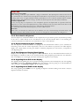
1
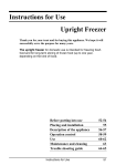
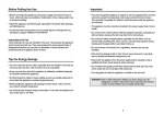
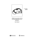
TATSUNO-BENČ EUROPE A.S.
Fuel Dispensers
of liquefied petroleum gas
BMP500.S/LPG and BMP2000.S/LPG
version SHARK
User Manual
© TATSUNO-BENČ EUROPE a.s.
25-08-2005
UP021-EN
L P G
U S E R M A N U A L
D I S P E N S E R S " S H A R K "
USER MANUAL
Fuel Dispensers
of Liquefied Petroleum Gas
BMP500.S/LPG and BMP2000.S/LPG
version SHARK
© TATSUNO-BENČ EUROPE a.s..
Pražská 2325/68 • 67801 Blansko
Tel.: +420 516 428411 • Fax: +420 516 428410
Czech Republic
e-mail: [email protected], http://www.benc.cz
© Copyright
Neither the manual in full nor any part of it may be reproduced without the
explicit approval of TATSUNO-BENČ EUROPE a.s.
2
LIST OF CONTENTS
0. INTRODUCTORY INFORMATION ............................................................................................................. 4
0.1. READ THE MANUAL THOROUGHLY FIRST ...................................................................................................... 4
0.2. BRIEF CHARACTERISTICS OF THE USED MEDIUM ........................................................................................... 5
1. LPG DISPENSERS TATSUNO - BENČ......................................................................................................... 6
1.1. BASIC SPECIFICATIONS .................................................................................................................................. 6
2. BASIC FUNCTIONS AND DISPENSER SETTING..................................................................................... 6
2.1. PDE CALCULATOR ........................................................................................................................................ 6
2.1.1. Remote Fuel Dispenser Control.............................................................................................................. 7
2.1.2. Setting of Parameters on Dispenser with Fuel Volume Display ............................................................. 8
2.1.3. Data Monitoring in Setting Mode ........................................................................................................... 8
2.1.4. Operator Mode........................................................................................................................................ 9
2.1.5. Manager Mode........................................................................................................................................ 9
2.1.5.1. Non-resetable totalizers (code 01) ..................................................................................................... 10
2.1.5.2. Daily totalizers (code 02)................................................................................................................... 10
2.1.5.3. Fuel Product Unit Prices (code 03) ................................................................................................... 10
2.1.5.4. Current Time and Date (code 04) ...................................................................................................... 12
2.1.5.5. Displaying of Program Version and Check Sum (code 05)................................................................ 12
2.1.5.6. Displaying of Latest Error Conditions of Fuel Dispenser (code 06) ................................................. 12
2.1.5.7. Displaying of History of Dispensing (code 07) .................................................................................. 13
2.1.5.8. Access Password (code 08) ................................................................................................................ 13
2.1.5.9. History of Maintenance (code 09)...................................................................................................... 13
2.1.5.10. Operating Fuel Dispenser Mode (code 12)...................................................................................... 13
2.1.5.11. Error Statistics (code 13) ................................................................................................................. 14
2.1.5.12. Current Operating Temperature (code 14) ...................................................................................... 14
2.1.5.13. Daily Totalizer Resetting (code 15).................................................................................................. 15
2.1.5.14. Operating Check Number (code 16) ................................................................................................ 15
2.1.5.15. Text messages (code 18)................................................................................................................... 15
2.1.5.16. Displaying of Display Segment Error (code 19) .............................................................................. 15
2.2. CALCULATORS PUMA HT-TE AND PUMA MPD........................................................................................... 15
3.3. CALCULATORS ADP/M AND ADPMPD/M.................................................................................................. 16
3. OPERATION................................................................................................................................................... 17
3.1. INSTRUCTIONS FOR SAFE OPERATION .......................................................................................................... 17
3.2. PUTTING LPG DISPENSER INTO OPERATION ................................................................................................ 17
3.3. OPERATION OF LPG FUEL DISPENSER ......................................................................................................... 18
3.3.1. Vehicle Refueling by LPG ..................................................................................................................... 18
3.3.2. Safety of LPG Fuel Dispenser Operation.............................................................................................. 18
3.3.3. Pre-selection Keyboard......................................................................................................................... 19
3.3.4. Electromechanical Litre Totalizers ....................................................................................................... 19
3.3.5. Fuel Dispenser Display Back-lighting .................................................................................................. 19
3.3.6. Signaling Diode SIG on the Display ..................................................................................................... 19
3.3.7. Signaling Diode PWR on the Display ................................................................................................... 19
4. MAINTENANCE AND SERVICE ................................................................................................................ 20
4.1. SURVEY OF MAIN PRINCIPLES OF LPG FUEL DISPENSER MAINTENANCE:...................................................... 20
4.2. LPG FUEL DISPENSER SERVICE ................................................................................................................... 21
4.3. WARRANTY AND COMPLAINTS .................................................................................................................... 21
4.4. ACCESSORIES ............................................................................................................................................... 21
5. DECLARATION OF CONFORMITY.......................................................................................................... 22
5.1. FUEL DISPENSERS LINE BMP500.S/LPG ..................................................................................................... 22
5.2. FUEL DISPENSERS LINE BMP2000.S/LPG ................................................................................................... 23
3
L P G
U S E R M A N U A L
D I S P E N S E R S " S H A R K "
0. Introductory Information
0.1. Read the Manual Thoroughly First
Read the relevant parts of the User Manual prior to start installing or operating the fuel dispenser. Consider all
hazards, attentions and notes contained in the Manual.
The Manual worked out by the manufacturer is the integral part of fuel dispenser accessories.
The user is liable fully for use of the Manual; any and all operations not described here shall be considered
forbidden. The operator carrying such operations shall be liable fully for consequences of his/her actions.
Each fuel dispenser has been tested from the points of its function, safety and metrology by the manufacturing
plant. Delivery of each individual fuel dispenser is accompanied by the certification documents, which shall be
submitted to the competent authorities by the user, if asked to do so.
CAUTION
•
The equipment has to be installed by the staff qualified and authorized pursuant to
relevant standards, regulations, local limitations and pursuant to the Manual.
•
Smoking and open fire handling is prohibited in the vicinity of the dispenser.
•
Always adhere to the rules for LPG handling.
•
Monitor all leaks in the dispenser. Should you establish fuel leaks, disconnect power
supply line and contact the service organization (see Section 5).
•
El. wiring must be carried out by the qualified staff.
•
Assure that the operable fire extinguisher is available.
•
When handling the device, use suitable protective aids.
4
0.2. Brief Characteristics of the Used Medium
LPG is the trade name for liquefied mix of light hydrocarbons, predominantly with three to four carbon atoms
in the molecule. LPG is obtained by synthetic petrol production and recently also by natural gas processing. The
liquefied LPG is a clear easily volatile liquid of specific odor.
By releasing overpressure the liquefied LPG is evaporated quickly and flammable gas, roughly twice as heavy as
air, is generated. By evaporation of liquefied LPG into air is generated explosive mix. which is heavier than air
and it is accumulated close to the earth.
Physical properties of liquid state
propane
butane
formula
C3H8
C4H10
molecular weight
44.09
boiling temperature (°C)
-42.6
58.12
-0.6
502
579
density (kg/m3 at atmospheric pressure)
1.865
2.76
consistency (air = 1)
1.562
2.091
93.57
123.76
bottom
1.7
1.3
upper
10.9
9.3
ignition temperature in °C
465
365
3
density (kg/m at 20°C)
Physical properties of gaseous state
3
LHV (MJ/m at 0°C and atmospheric pressure)
Explosion limit, when mixed with air, in % vol.
Table 1 - Physical properties of main LPG mix components
Gaseous LPG has moderately narcotic effect on the human organism. Breathing of gaseous LPG causes, after
some time of action, headache, nausea, weariness, dissipated attention, drowsiness. If not ignited, the gaseous
LPG may cause suffocation of the operators, though it is not poisonous directly, like e.g. the city gas. As it is
heavier than air, it is accumulated close to the earth and in the recesses and the laying person (lost consciousness
in case of injury, etc.) may occur in the oppressive atmosphere. Gaseous LPG also causes skin degreasing.
The liquefied LPG is evaporated - after the steep drop of overpressure to the atmospheric pressure (e.g. leak of
the liquefied LPG out of the device) - by boiling under the temperature of -42°C, and therefore contact of the
skin with the liquefied LPG results in frostbites.
5
L P G
U S E R M A N U A L
D I S P E N S E R S " S H A R K "
1. LPG Dispensers TATSUNO - BENČ
1.1. Basic Specifications
Dispensed medium
Max. flow rate
Qmax
Min. flow rate
Qmin
Min. volume of refueling
Vmin
Operating pressure
p
Max. operating pressure
pmax
Rated pressure
pN
Accuracy of dispensing
Operating temperature of the ambient air
Operating temperature of the medium
liquid propane-butane
50 dm3. min-1
5 dm3. min-1
5 dm3
1.6 MPa
1.8 MPa
2.5 MPa
± 1%
- 30 ÷ + 50°C
- 20 ÷ + 50°C
Electronic calculator:
Power
~230 V; +10% -15%; 50 Hz ± 5 Hz
max. 84 VA
2. Basic Functions and Dispenser Setting
Setting of the LPG dispensers is done by the set of parameters, by which functional dispenser parameters can be
controlled, mode and behaviour of the dispenser in different situations changed materially. Values of the
parameters can be monitored and changed either by the remote IR controller or by the functional keys placed
directly on the calculator or on a simple keyboard, being the integral part of the calculator assembly.
Method of setting of the fuel dispenser differs, depending on the type of the used calculator placed in the
dispenser head. The section below describes basic functions and setting for the calculators PDE, Puma HT-TE,
Puma MPD, ADP and ADPMPD.
2.1. PDE Calculator
The calculator PDE, manufactured by the company TATSUNO-BENČ EUROPE a.s., is set by the remote IR
controller (marked PDERT). The setting mode serves for monitoring and change of
the parameters and provides the following operations:
•
•
•
•
displaying of non-resetable electronic volume and cash amount totalizers of all
hoses
displaying and reset of daily electronic volume and cash amount totalizers of all
hoses
setting of unit product prices (manual mode)
setting of different functional parameters of the dispenser
The setting mode can be recalled on the dispenser by the method below only if the
dispenser is at rest (completed dispensing, all nozzles are accommodated in the
boots). There are two setting modes available:
6
•
Operator mode (specified for filling station operators) – the operator can only read values of electronic
totalizers and values of basic dispenser parameters. The operator can neither reset nor change their values.
•
Manager mode (specified for the filling station manager) – The manager is authorized both to read the
values, reset daily totalizers and to set basic operating parameters of the LPG dispenser. The manager must
load the access password to be able to work in the manager mode.
2.1.1. Remote Fuel Dispenser Control
A special remote IR controller must be used for reading dispenser values (totalizers), change of the dispenser
mode or for setting different calculator parameters on the LPG dispensers equipped by the PDE calculator.
The Remote controller keyboard had the following keys and their layout:
Key
function
key
OPERATING STATE
<Shift>< Enter>
<0>
<1>
<2>
<3>
<4>
<5>
<6>
CALCULATOR PARAMETER READING
Release of dispenser side after payment or
failure
Release of both sides (whole fuel dispenser)
after payment or failure
Preset - depressing of corresponding preset
key No. 3 (10 litres)
Preset - depressing of corresponding preset
key No. 4 (1 litre)
<Next>
Displaying of the latest refilling on the display
<+>
Switching to next parameter item
<0> až <9>
<REG>
Switching to previous parameter item
Changed value of the displayed parameter (if
the operation is permitted )
Direct switching to the parameter with preset
number
End of selected mode
CHANGE OF PARAMETER VALUE AND LOADING OF
ACCESS
Loading of value of the edited digit and
<0> až <9>
switching to the next figure
Lighting fuel dispenser ON
<8>
Displaying of converted CNG gas volume (if the
function is activated))
<9>
Lighting fuel dispenser OFF
<+>
<Shift> < + >
START OF SETTING MODES
<REG>
Switching to previous parameter
< Enter >
Preset - depressing of corresponding preset
key No.1 (CZK 100)
Preset - depressing of corresponding preset
key No.2 (CZK 10 )
Cancel of preset on one fuel dispenser side
(preset key No.5 – Cancel)
Switching to next parameter
<Shift> <Next>
<Shift> < + >
<7>
<Shift> <REG>
function
Commences the operator mode
Commences the manager mode (upon loading
the password)
7
Increase of value of just edited parameter digit
Decrease of value of just edited parameter
digit
<Next>
Switching to editing of the next parameter digit
<Shift> <Next>
Switching to editing of the previous parameter
digit
< Enter >
End of change and loading of a new value
<Shift>< Enter>
End of change w/o loading of a new value
L P G
U S E R M A N U A L
D I S P E N S E R S " S H A R K "
2.1.2. Setting of Parameters on Dispenser with Fuel Volume Display
The process of setting is similar to that of the classic three-line display, only functions of certain keys on the
remote controller keyboard differ.
Basic principles of setting in the manager and service mode:
1. The manager mode is entered by depressing the key <REG>. The word „CODE“ appears for ca 1 second
on the display. Now the password must be loaded. After loading the correct password and confirmation by
the key <Enter> the volume display will shown „-0“ and the dispenser waits for loading the relevant
parameter digit.
2. Switching between the parameters - by the keys <Next> and <Shift><Next>, between sub-parameters by <+> and <Next> <+>
3. To display value of the parameter on the line “Litres” (fuel volume) - depress the key <1>. To display value
of the parameter on the line „Price“ (cash amount) - depress the key <2>. The key <Shift> <Enter>
again displays the number of the parameter (i.e. displays the line „Kč/litr“ - unit grade price)
4. Change (editing) of parameter value - by the key <Enter>
5. Mode exit - by the key <REG>
Viewing of the parameters (totalizers) in the operator mode is done in the same way. When depressing the key
<Shift> <REG>, the first parameter 01 will appear automatically. Switching between the parameters - by the
keys <Next> and <Shift> <Next>, between sub-parameters - by <+> and <Shift> <+>. By depressing
the keys <1> and <2>, parameter values can be monitored. Operator mode exit - by depressing the key
<REG>.
2.1.3. Data Monitoring in Setting Mode
All data in the setting modes are displayed on the dispenser display. When controlling by the remote controller,
the data are displayed on the dispenser side, which the setting mode was recalled from (by the controller).
Individual parameters are displayed as follows:
00003.2
Amt
7890.13
Ltrs
01.L2
Price
Parameter number :
01
Item number:
2
Auxiliary code:
L
Parameter value: 327890,13
Item number
Auxiliary code
Parameter number
8
2.1.4. Operator Mode
The operator mode is started by pointing the dispenser display by the IR remote controller (at the distance of ca
1 m from the dispenser) and by depressing the key <Shift> and then the key <REG>. All nozzles must be
locked securely in the boot !!
After the operator mode is recalled, value of the first parameter is displayed. Switching to the next parameters
and their items is carried out using the keys <Next> and <+> (see sec. 3.1.1.).
The operator mode enables to display (but not change !!) the following parameters:
Param.
01
02
03
04
05
06
07
Description
Non-resetable totalizers
Daily totalizers
Unit fuel product prices
Current time and date
Version of program and CRC parameters (check total)
History of failures
History of dispensing
The operator mode is ended by depressing the key <REG> on the remote controller. The mode is also ended
automatically, if no key is depressed for 60 seconds.
2.1.5. Manager Mode
The manager mode is started by pointing the dispenser display by the remote controller (at the distance of ca 1
m from the dispenser) and by depressing the key <REG>. All nozzles must be locked securely in the boot !
After the manager mode is recalled, the display shows the prompt for loading the 4-digit access password:
----
Amt
To have the password secret, the loaded digits are displayed as
points. The manufacturer has set the access password : „1111“.
Ltrs
Example:
Depress the keys <1><1><1><1> and <Enter>
CODE Price
Amt
- 0 Ltrs
00
Price
After the valid password is loaded, the display shows the
parameter number 00; by depressing the key <Enter> you can
continue by automatic switching to the parameter No. 01, or it is
possible to load the parameter number and <Enter> for
direct switching to the requested parameter. After the manager
mode is recalled, value of the first parameter will be displayed.
9
L P G
U S E R M A N U A L
D I S P E N S E R S " S H A R K "
The manager mode enables to display and change (set) the following parameters:
Para
m.
01*
02
03
04
05*
06*
07*
08
09
10
Description
Non-resetable totalizers
Daily totalizers
Unit prices of the products
Current time and date
Version of program and CRC
number
History of failures
History of dispensing
Access password
History of maintenance
- unused -
11
12
13*
14*
15
- unused Fuel dispenser operating mode
Statistics of failures
Current operating temperature
Reset of daily totalizers
16
17
18
19
Operating check number
- unused Text messages of LCD alphanumeric display
Displaying of display segment error
Parameters marked by asterisk (*) can be viewed only in the manager mode, not set
The manager mode is ended by depressing the key <REG> on the remote controller. The mode is also ended
automatically, if no key is depressed for 60 seconds.
2.1.5.1. Non-resetable totalizers (code 01)
Electronic totalizers of all hoses (meters) are stored in electronic calculator memory. These totalizers are nonresetable and show how many litres were dispensed by individual hoses.
item number
1
2
…
9
H
description
volume dispensed by the hose 1 in litres
volume dispensed by the hose 2 in litres
…
volume dispensed by the hose 9 in litres
volume dispensed by the hose 10 in litres
2.1.5.2. Daily totalizers (code 02)
The electronic daily totalizers of all hoses (meters) are stored in electronic calculator memory. These totalizers
can be reset at any time (manager mode - parameter 15). The daily totalizers show, what fuel volume /cash
was dispensed by individual hoses since the latest resetting.
aux. code
L
A
L
…
A
L
A
item number
1
1
2
…
9
H
H
description
volume dispensed by the hose No.1 in litres
amount dispensed by the hose No.1 in currency
volume dispensed by the hose No.2 in litres
…
amount dispensed by the hose No. 9 in currency
volume dispensed by the hose No.10 in litres
amount dispensed by the hose No.10 in currency
2.1.5.3. Fuel Product Unit Prices (code 03)
The function enables to display and set current unit prices of all fuel products (i.e. prices per 1 litre of fuel) sold
for cash.
item number
1
2
3
4
5
description
unit price of product 1
unit price of product 2
unit price of product 3
unit price of product 4
unit price of product 5
default setting
00.00
00.00
00.00
00.00
00.00
10
If the fuel dispenser (calculator) is connected to the control system, then the price is updated after each calculator
activation, namely by the product values set in the control system
11
L P G
U S E R M A N U A L
D I S P E N S E R S " S H A R K "
2.1.5.4. Current Time and Date (code 04)
The function enables to display and set the current date and time. Setting can be done by depressing the key
<Enter> and by loading date and time.
17345.0
Amt
2405.00 Ltrs
04
Price
Time
Parameter
Date
The first line displays time in the format HHMMSS (hours, minutes and seconds), the second line displays date
in the format DDMMYY (day, month and year) - example 17:34:50 24.05.00
2.1.5.5. Displaying of Program Version and Check Sum (code 05)
The function displays the number of the program version of the dispenser calculator and the check sum of
memory parameters.
•
•
Line 1 (amount) – check sum
Line 2 (litres) - version number (e.g. 3.34 - version 3.34)
2.1.5.6. Displaying of Latest Error Conditions of Fuel Dispenser (code 06)
The function serves for displaying of the history of the latest ten error codes of faults, occurred on the dispenser.
Table of error messages can be found in the Appendix D.
aux. code
A
B
A
B
…
A
B
item number
0
0
1
1
…
9
9
description
code of the last (tenth) error of the dispenser on display side A
code of the last (tenth) error of the dispenser on display side B
code of the last but one (ninth) error of the dispenser on side A
code of the last but one (ninth) error of the dispenser on side B
…
code of the error (first in the history) of the dispenser on side A
code of the error (first in the history) of the dispenser on side B
Amt
12344.5
Amt
2304.00
Ltrs
„E“
.18 Ltrs
„E“
06A0
06A0
Price
Price
Error Time
Parameter
Side
Order
Error
Parameter
12
Side
Order
Error Date
2.1.5.7. Displaying of History of Dispensing (code 07)
The function serves for displaying of the history of the latest 10 dispensing transactions (on each side) realized
on the dispenser. Data layout of this parameter on the display is as follows:
500.0
Amt
12344.5
Amt
2304.00
Ltrs
„E“
20.00 Ltrs
„E“
07A0
07A0
Price
Amount
Parameter
Side
aux. code
A
B
A
B
…
A
B
item number
0
0
1
1
…
9
9
Order
Volume
Price
Fuelling Time
Parameter
Side
Order
Fuelling Date
description
last transaction (tenth) on side A
last transaction (tenth) on side B
last but one transaction (ninth) on side A
last but one transaction (ninth) on side A
…
transaction (first in the sequence) on side A
transaction (first in the sequence) on side B
The first and second line contain price (cash amount) and dispensed volume. The unit price of the transaction
with the parameter number and the auxiliary code with the item number take turns on the third line. Number of
the item means position in the history of transactions - 0 is the last (newest) transaction, 9 is the oldest stored
transaction. The auxiliary code means the dispenser side A or B. If the memory stack for the history of
transactions is empty (i.e. there is no transaction in the history), “error” appears on the display.
2.1.5.8. Access Password (code 08)
The function enables to display and change the access password into the manager mode.
Default setting is „1111“.
2.1.5.9. History of Maintenance (code 09)
The function enables to display codes of the last 10 service remote controllers which the calculator parameters
were set by.
2.1.5.10. Operating Fuel Dispenser Mode (code 12)
The function defines the type of operating fuel dispenser mode.
parameter
value
0
1
2
3
4
Operating fuel dispenser mode
Automatic mode
Manual with switching to the automatic mode (default)
Manual with switching to the automatic mode and locking
Manual (stand alone) mode
Credit (internal credit - "Chipper")
13
L P G
U S E R M A N U A L
D I S P E N S E R S " S H A R K "
The parameter may obtain the values in the range from 0 to 4 (the value 4 may be set for the credit version PDE only!)
•
If value of the parameter equals to 0, the fuel dispenser is operated in the pure automatic mode i.e. it is
connected to the master computer (console). The fuel dispenser is controlled by the computer fully (fuel
dispenser release, locking, setting of fuel prices, etc.). Interrupted communication between the computer and
the fuel dispenser is subject to the error message E 18 which appears on the display.
•
If value of the parameter equals to 1, the fuel dispenser is operated in the manual mode (see the mode No.
3) until it is connected to the master computer. Then the computer is switched automatically to the
automatic mode (see the mode No.1). Interrupted communication between the computer and the fuel
dispenser is subject to the error message E 18 which appears on the display.
•
If value of the parameter equals to 2, the fuel dispenser is operated in the manual mode (see the mode No.
3) until it is connected to the master computer. Then the computer is switched automatically to the
automatic mode (see the mode No.1). Unlike the mode 2, the fuel dispenser is locked after each transaction
and has to be unlocked by the magnets or by the remote controller by depressing the key <0>. Interrupted
communication between the computer and the fuel dispenser is subject to the error message E 18 which
appears on the display.
•
If value of the parameter equals to 3, the fuel dispenser is operated in the pure manual mode. The fuel
dispenser is independent fully (cannot be connected to the computer). Unit fuel prices may be set by the fuel
dispenser parameter No. 3.
•
If value of the parameter equals to 4, the fuel dispenser is operated in the credit mode. The fuel dispenser
may be switched to this mode only if the fuel dispenser is equipped by the credit module PDECRE and the
switch cash/Credit is in the position "ON".
2.1.5.11. Error Statistics (code 13)
The function serves for displaying statistics of the errors which took place on the fuel dispenser since the
moment of initialization or resetting of the electronic calculator. This parameter has differing data arrangement
on the display:
5 Amt
E
7 Ltrs
13
Price
Error code
Parameter
Error frequency
The first and second line contain the fault code and the frequency rate of the fault in question.
2.1.5.12. Current Operating Temperature (code 14)
The function displays the current temperature measured by the temperature sensor placed on the processor
board.
• line 1 (Amount) – operating calculator temperature
• line 2 (Litres) - temperature of the product 1, 2, 3 or 4 (only if the temperature sensors are installed)
14
2.1.5.13. Daily Totalizer Resetting (code 15)
The function serves for resetting of all daily totalizers (registers) of the dispensing hoses.
After setting the parameter value to 1 and after confirmation all totalizers will be reset.
2.1.5.14. Operating Check Number (code 16)
The function serves for displaying of the 6-digit operating check number and for operating code loading.
• 1 line 1 (Amount) – operating check number
2.1.5.15. Text messages (code 18)
If the fuel dispenser is equipped by the alphanumeric display, the function enables to set the text messages which
will appear on the alphanumeric display.
2.1.5.16. Displaying of Display Segment Error (code 19)
The function enables/disables displaying of the display segment error (El) by the processor.
Parameter
value
0
1
Description
Do not display the error of the display segment
Display the error of the display segment - default setting
2.2. Calculators Puma HT-TE and Puma MPD
The calculators Puma HT-TE and Puma MPD produced by the company Gilbarco Veederoot S.p.A. (the
former company Logitron) are set by the three-key keyboard.
Functions of the keys are as follows:
Key
<->
<+>
Function
Entry into the price setting mode (after calculator switching )
Selection of figures on the unit price display
Value increase
Price setting (for manual mode)
Unit price setting is done in the manual mode namely as follows:
•
switching the calculator ON/OFF
•
display mask removal
•
depressing the key <-> (the calculator is switched to the price setting
mode)
•
selection of the figure for the price, the value of which is to be changed
by the key <->
•
setting of the value of the selected figure by the key <+>
•
display mask mounting
•
switching the calculator ON/OFF
Setting or monitoring of parameters
This operation is reserved to service technicians (servicemen) only !!!
15
L P G
U S E R M A N U A L
D I S P E N S E R S " S H A R K "
3.3. Calculators ADP/M and ADPMPD/M
The calculators ADP and ADPMPD produced by the company Beta Control s.r.o. are set, using the IR manager
keyboard KL-MANINF provided with four keys <R>, <0>, <+> and <->.
Functions of the keys are as follows:
Key
Function
<0>
Entry into the price setting mode (after calculator switching)
<->
Selection of figures on the unit price display. Selection of the product (grade) for pricing
<+>
Value increase. Entry into the mode of totalizer reading (fuel dispenser at rest)
Price setting (for manual mode)
Unit price setting is done in the manual mode only, namely as follows:
•
switching the calculator ON/OFF
•
directing the fuel dispenser display by the IR keyboard and depressing the key <0>
•
selection of the figure for the price, the value of which is to be changed by the key <->
•
setting of the value of the selected figure by the key <+>
•
switching to another product /grade (dispensing hose) by the key <->
•
end of setting by depressing the key <0>
Displaying of electronic totalizers
Displaying of the electronic totalizer is carried out as follows:
•
the fuel dispenser is at rest, all transactions are transferred to the POS and all nozzles are suspended in the
boot
•
by directing the IR keyboard onto the fuel dispenser display and by depressing the key <+> , the volume
(litre) totalizer of the first nozzle will appear - e.g. "U0000012345.90"
•
by depressing the key <+>, the sum totalizer of the first nozzle will appear - e.g. "A00000235678.9"
•
by depressing the key <+>, volume and price totalizers for other nozzles will appear
• totalizer reading is ended by depressing the key <0>
Setting or monitoring of parameters
This operation is reserved to service technicians (servicemen) only !!!
16
3. Operation
3.1. Instructions for Safe Operation
CAUTION
● Technical and technological equipment must comply with the approved conditions which comprise
the instructions for safe operation and maintenance as well as solution of emergency states. Snow fire
extinguishers must be available close to the device in conformity with the fire safety rules.
● Only the persons that have provably passed the training may operate the LPG pumping station.
● The fuel dispenser is equipped by the “STOP button” (for emergency situations); the procedure in
case of fire or emergency situation is determined precisely by the local bylaws - the operator must be
trained correspondingly.
● The “STOP line” must be placed 5 m from the fuel dispenser as a minimum.
● LPG storage tanks, pipelines and the dispenser must be earthed, the earthing point for the road
tanker must be marked explicitly.
● When refueling, re-pumping and emptying LPG, the issued regulations have to be adhered to, arrival
and operation in the specified pumping station premises prevented according to the local conditions.
● When selling and pumping LPG, the determined procedure has to be adhered to; in case of any
danger the device must be put out of operation immediately. When refueling, the operator of the
pumping station must be present; refueling is prohibited during storms (danger of atmospheric
discharges).
● It is necessary to keep the preset deadlines for regular inspections and checks of the complete
installed unit; intervention of the persons without relevant competence, capability and qualification
into the installed technology, incl. the gas appliance, must be prevented safely.
● The operator may not carry out any repairs of the devices and change setting of the safety fittings.
Regular maintenance and service may be carried out by the authorized service company only.
● The operator shall keep the device in intact and safe state; any defect or unusual phenomenon shall
be notified to the service organization immediately; in case of danger of delayed intervention the device
must be put out of operation.
CAUTION
•
•
•
•
Smoking and open fire handling is prohibited in the vicinity of the dispenser.
Smoking is prohibited also for the persons sitting in the car.
It is prohibited to use the mobile phone in the vicinity of the dispenser.
It is prohibited to dispense if the motor is running.
3.2. Putting LPG Dispenser into Operation
Switching the fuel dispenser ON/OFF is carried out in the master switchboard of the filling station, where fuel
dispenser feeders are connected. Each fuel dispenser has three power supply outlets in the master switchboard:
•
feeding of electronic calculator (230V stabilized)
•
feeding of valve switching (230V non-stabilized)
All points above are protected by relevant circuit breakers, by which the fuel dispensers are switched ON/OFF.
LPG dispensers with calculators Puma HT-TE and Puma MPD have only the outlet for electronic calculator
feeding (230V stabilized) in the main switchboard.
17
L P G
U S E R M A N U A L
D I S P E N S E R S " S H A R K "
3.3. Operation of LPG Fuel Dispenser
Prior to start refueling, the fuel dispenser operator shall check whether the tank has the homologation mark and
whether the motor and el. equipment of the vehicle are switched off. The operator also inspects state and/or
wear of the filler which might cause gas leaks. If serious defects are revealed, the operator may reject tank
refueling. In case of gas leaks or any danger the operator stops refueling.
3.3.1. Vehicle Refueling by LPG
Operation of the fuel dispenser itself is provided by the filling station staff who releases the nozzle from
the fuel dispenser and connects it with the fuel tank of the vehicle which must be braked reliably. When
depressing the control button on the calculator box, the el. calculator is reset and the pump el. motor
placed next to the standby fuel reservoir started. Refueling can be stopped at any time be releasing the
control button. When filling the “full” tank, the filling tank neck is closed as soon as 80% of the tank
volume is refueled and the safety controller (el. calculator) interrupts refueling after 10 seconds,
irrespectively of the control button. The data remain displayed on the calculator.
The fuel dispensers equipped by electronic pre-selection enable to preset precise requested amount, determined
by volume or by price. These fuel dispensers are equipped by the double-stage electromagnetic valve.
DUTIES OF LPG FUEL DISPENSER OPERATOR
•
•
•
•
•
•
•
•
Adhere to the bylaws and operation manuals of gas appliances.
Maintain the operated device in safe and workable state.
Notify any fault, defect, unusual phenomena revealed during operation to the filling station owner
immediately.
Put the device out of operation in case of gas leak or another danger.
Keep the device in order and clean and prevent unauthorized persons from access.
Notify the events, making the operator’s work problematic/difficult, to the owner.
Record the data concerning start and end of every shift, inspections, repairs and reviews duly into
the operating log book.
Operator of the fuel dispenser and fuel tank may neither carry out any repairs by himself nor change
setting of the equipment or safety fittings.
OPERATOR’S OUTFIT
•
•
•
soap (foamy) solution + brush for detection of leaks
leather gloves
the first-aid-kit, log book, writing utensils, operating and safety rules, wiring diagram of the fittings and
fire extinguisher must be available in the filling station kiosk
3.3.2. Safety of LPG Fuel Dispenser Operation
Owner of the filling station is liable for its operation which shall be entrusted to the trained staff only, having
relevant authorization. The operator refuels vehicle tanks by LPG professionally, checks state of the fuel
dispenser and the technology in the preset time intervals, checks operation of the whole unit and maintains
operating records. The prohibit of smoking and open fire handing in the area of 10 m must be fixed on a visible
places next to the fuel dispenser. The notice of necessary motor switch-off, max. volume of refueling (80%) and
braking the vehicle from undesirable motion has also be placed here. From the design point of view the fuel
dispensers and all components which might initiate explosion are approved by the state authorized institution the State Testing Laboratory No. 210 FTZÚ Ostrava-Radvanice, which issues the necessary certificates.
Environmental safety is supported by ČIŽP Certificate No. 90/00/895/01/TOM.
For detection of possible gas leaks relevant detectors/sensors can be installed in the fuel dispenser area - the
sensors are out of scope of the basic offer. From the hygienic point of view the device is harmless for the
operator and the owner. When operating and maintaining the device, it is advisable to protect the hands by
gloves.
18
FIRST AID
Poisoning-gaseous LPG
When refueling, avoid LPG vapor inhalation - danger of suffocation. The injured person must be taken out of
the contaminated area. Attention! Fire and explosion hazard! LPG is not poisonous, but is suffocating. In case of
breathing failure carry out apply artificial breathing immediately. In case of blood circulation failure combine
artificial breathing with indirect heart massage. Transfer the affected person the heath facility immediately.
Frostbites-liquid LPG
In case of steep drop of overpressure to the atmospheric pressure the liquid LPG is evaporated under the
temperature of -42°C. Leak of the liquid LPG may result in frostbites, when in contact with the skin. Do not rub
the frostbitten parts of the body, but cover by a sterile dressing and call the doctor.
Eyes affected by LPG shall be flushed by plenty of water. Call the doctor.
Burns-fire
When burnt, cool the injury by cold water, do not lubricate, cover by a sterile dressing and call the doctor. Do
not remove the dress. If the clothes are burnt - do not run, extinguish by water, blanket, by rolling about ....
3.3.3. Pre-selection Keyboard
The LPG dispensers TATSUNO BENČ can be completed by the pre-selection (preset) keyboard for presetting
of the sum or volume directly on the fuel dispenser by the customer himself. Prior to start refueling, the
customer can decide how much fuel or for what price he wants to refuel himself.
3.3.4. Electromechanical Litre Totalizers
The fuel dispensers TATSUNO-BENČ are equipped by electromechanical totalizers (as the standard) for
monitoring of the total fuel volume dispensed by each hose. The totalizers are placed on the LPG dispenser
display. One 7-digit totalizer, showing the number of full litres pumped by the relevant hose, corresponds to
each dispensing hose.
3.3.5. Fuel Dispenser Display Back-lighting
Displays of all fuel dispensers are back-lighted by SMD LED diodes. In case of the PDE calculator intensity of
back-lighting is controlled as follows: the maximum intensity during dispensing and reduced to one third if the
data on the display are not changed (automatic switching after expiration of 30 seconds).
3.3.6. Signaling Diode SIG on the Display
The signaling diode signaling the state of payment, blocking and fault of the fuel dispenser (red). The signaling
diode SIG is switched to continuous red light, if the fuel dispenser waits for paying or is in the blocked state
and is switched to the blinking red light if the fuel dispenser is faulty.
3.3.7. Signaling Diode PWR on the Display
The orange signaling diode PWR serves for signaling of dispenser calculator feeding. If the diode is ON, the
dispenser calculator is actuated.
19
L P G
U S E R M A N U A L
D I S P E N S E R S " S H A R K "
4. Maintenance and Service
CAUTION
Prior to start any maintenance intervention into mechanical, hydraulic or electric parts /assemblies, it
is always necessary to disconnect the fuel dispenser from the power supply source and to protect it
from re-connection reliably.
CAUTION
DO NOT OPEN THE JUNCTION BOX COVER IF THE FUEL DISPENSER IS ENERGIZED !
CAUTION
Each handling and dismantling operation of the parts and assemblies above (even filter cover
opening) is conditioned by forcing the medium out of the fuel dispenser hydraulic system, using
nitrogen or inert gas!
Electric and electronic parts/assemblies may be serviced only and exclusively by the specialist
liable for safety of the device. After completed intervention the conductors must be reinstated.
Correct conductor installation must prevent any contact with the moving parts of the winding
module.
Caution! After each service intervention tightness of hydraulic assemblies has to be inspected; possible
medium leaks have to be removed.
4.1. Survey of main principles of LPG fuel dispenser
maintenance:
•
•
maintain all fuel dispenser assemblies clean so that possible unforeseeable fault can be identified easily and
removed quickly
check condition of the nozzle and decide its repair or replacement, depending on revealed defect
•
check door locks and nozzle accommodation boot for correct functioning
•
maintain the fuel dispenser clean, pay attention particularly to cleanliness of calculator glass
•
lubricate the nozzle by silicone oil twice a week
Maintenance of fuel dispenser “body”:
Parts of the fuel dispenser body, lacquered or made of stainless steel need regular maintenance. A great attention
shall be paid to these parts particularly in winter season, because aerosols of chloride preparations arisen from
the salts used for road maintenance can result in permanent damage of lacquers of untreated body parts and/or
to intercrystalline corrosion - guards made of stainless steel. Regular maintenance of fuel dispenser body is
carried out by water and/or by solution of detergents and available car cosmetic preparations.
Owner of the fuel dispenser shall:
•
•
•
•
Appoint one staff member liable for operation and workability of the fuel dispenser.
Provide inspections, testing, repairs and maintenance by the professional method.
File documents and operating records.
Any and all activities connected with operation and service of the LPG fuel dispenser may be carried out
only and exclusively by the staff with relevant authorization.
20
Principles of LPG Fuel Dispenser Checking
Check of equipment, tanks, pipe distribution lines and fuel dispensers are carried out with the periodicity, fixed
by the bylaws of the filling station in accordance with the valid regulations.
• Check the fuel dispenser hydraulic system for tightness (by soap solution).
• Check of machinery (equipment).
• Check of non-return and safety valve for correct functioning
• Inspection, calibration and official verification of the LPG fuel dispenser is carried out by the relevant
institute abroad.
• The inspection is preceded by cleaning of the whole device, clearing the tanks of dust, water and other
impurities.
Fuel Dispenser Error Messages
Defect of the fuel dispenser leads to locking of the operation of refueling and to displaying of the error message
on the fuel dispenser display. Nearly all error messages may be cleared by nozzle release and back suspension, by
switching the electronic unit feeder ON/OFF and/or by depressing "0" on the remote controller (only the PDE
electronic unit).
4.2. LPG Fuel Dispenser Service
•
•
•
•
•
•
•
•
service operations are carried out in conformity with the operation rules of the filling station
prior to start the works, the fuel dispenser must be put out of operation; the fuel dispenser must
be affixed by a visible label “OUT OF OPERATION” and the approach lane must be marked by
the sign “NO ENTRY”
the fuel dispenser must be disconnected from the power source (switching OFF the master
switch in the switchboard)
propane-butane must be forced out of the whole system, incl. the fuel dispenser (except for the
tank) by nitrogen, prior to start any works
valves on the supply and return piping must be closed fully
traffic of the vehicles must be prevented at the distance of 5 m round the fuel dispenser in the
course of service activities
fire extinguisher must be available for the staff
the service intervention must be carried out by the trained staff of the service company
4.3. Warranty and Complaints
The contractual warranty is determined - the manufacturer warrants for the supplied unit for 2 years or 1
million liters of dispensed medium as a standard. The warranty does not cover the consumables (e.g. the
tubular discharge lamps). When raising possible claims, the following data have to be specified:
• Serial number and name - see the rating plate
• Precise description of fault and the circumstances under which the fault occurred.
The claim will not be acknowledged provided that damaged seals or non-permitted intervention into the unit
were established. Defects and drawbacks following from incorrect operation, inspection and maintenance of the
fuel dispenser or its functional assemblies are out of scope of the warranty (e.g. the problems caused by presence
of water and impurities in the tank and the hydraulic system). Check for presence of water and impurities and
possible cleaning is necessary in the course of operation.
4.4. Accessories
•
•
•
•
•
•
Installation and User Manual
Certificate of Quality and Completeness
Certificate of Conformity
Pressure Test Report
IR controller for operation and programming of the calculator - for the BG PDE el. calculator
Foundation frame (a special order)
21
L P G
U S E R M A N U A L
D I S P E N S E R S " S H A R K "
5. Declaration of conformity
5.1. Fuel Dispensers line BMP500.S/LPG
22
5.2. Fuel Dispensers line BMP2000.S/LPG
23