1
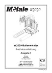
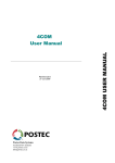
TATSUNO-BENČ EUROPE A.S.
Liquid Fuel Dispensers of series
BMP500.S and BMP2000.S
version SHARK
User Manual
© TATSUNO-BENČ EUROPE a.s.
25-08-2005
UP020-EN
F U E L
D I S P E N S E R S
F O R
U S E R M A N U A L
L I Q U I D F U E L
USER MANUAL
Liquid Fuel Dispensers of series
BMP500.S and BMP2000.S
version SHARK
© TATSUNO-BENČ EUROPE a.s..
Pražská 2325/68 • 67801 Blansko
Tel: +420 516428411 • Fax: +420 516428410
e-mail: [email protected], http://www.benc.cz
© Copyright
Neither the manual in full nor any part of it may be reproduced without the
explicit approval of TATSUNO-BENČ EUROPE a.s.
2
LIST OF CONTENTS
0. INTRODUCTORY INFORMATION ............................................................................................................. 4
1. FUEL DISPENSERS TATSUNO BENČ......................................................................................................... 5
1.1. BASIC SPECIFICATIONS .................................................................................................................................. 5
2. BASIC FUNCTIONS AND DISPENSER SETTING..................................................................................... 5
2.1. PDE CALCULATOR ........................................................................................................................................ 5
2.1.1. Remote Fuel Dispenser Control.............................................................................................................. 6
2.1.2. Setting of Parameters on Dispenser with Fuel Volume Display ............................................................ 8
2.1.3. Data Monitoring in Setting Mode ........................................................................................................... 8
2.1.4. Operator Mode........................................................................................................................................ 9
2.1.5. Manager Mode........................................................................................................................................ 9
2.1.5.1. Non-resetable totalizers (code 01) ..................................................................................................... 10
2.1.5.2. Daily totalizers (code 02)................................................................................................................... 10
2.1.5.3. Fuel Product Unit Prices (code 03) ................................................................................................... 10
2.1.5.4. Current Time and Date (code 04) ...................................................................................................... 11
2.1.5.5. Displaying of Program Version and Check Sum (code 05)................................................................ 11
2.1.5.6. Displaying of Latest Error Conditions of Fuel Dispenser (code 06) ................................................. 11
2.1.5.7. Displaying of History of Dispensing (code 07) .................................................................................. 12
2.1.5.8. Access Password (code 08) ................................................................................................................ 12
2.1.5.9. History of Maintenance (code 09)...................................................................................................... 12
2.1.5.10. Operating Fuel Dispenser Mode (code 12)...................................................................................... 12
2.1.5.11. Error Statistics (code 13) ................................................................................................................. 13
2.1.5.12. Current Operating Temperature (code 14) ...................................................................................... 13
2.1.5.13. Daily Totalizer Resetting (code 15).................................................................................................. 13
2.1.5.14. Operating Check Number (code 16) ................................................................................................ 14
2.1.5.15. Text messages (code 18)................................................................................................................... 14
2.1.5.16. Displaying of Display Segment Error (code 19) .............................................................................. 14
2.2. CALCULATORS PUMA HT-TE AND PUMA MPD........................................................................................... 14
2.3. CALCULATORS ADP AND ADPMPD ........................................................................................................... 15
3. OPERATION................................................................................................................................................... 16
3.1. INSTRUCTIONS FOR SAFE OPERATION .......................................................................................................... 16
3.2. PUTTING FUEL DISPENSER INTO OPERATION ............................................................................................... 16
3.3. FUEL DISPENSER OPERATION ....................................................................................................................... 16
3.3.1. Dispensing............................................................................................................................................. 16
3.3.2. Electromechanical Litre Totalizers ....................................................................................................... 17
3.3.3. Fuel Dispenser Display Back-lighting .................................................................................................. 17
3.3.4. Signaling Diode SIG on the Display ..................................................................................................... 18
3.3.5. Signaling Diode PWR on the Display ................................................................................................... 18
3.3.6. Fuel Dispenser Operation Modes ......................................................................................................... 18
3.3.7. Preset Keyboard.................................................................................................................................... 19
4. MAINTENANCE AND SERVICE ................................................................................................................ 20
5. SOLUTION OF PROBLEMS ........................................................................................................................ 22
6. DECLARATION OF CONFORMITY 23
6.1. FUEL DISPENSERS LINE BMP500.S.............................................................................................................. 23
6.2. FUEL DISPENSERS LINE BMP2000.S............................................................................................................ 24
3
F U E L
D I S P E N S E R S
F O R
U S E R M A N U A L
L I Q U I D F U E L
0. Introductory Information
Read the relevant parts of the User Manual prior to start installing or operating the fuel dispenser. Consider all
hazards, attentions and notes contained in the Manual.
The Manual elaborated out by the manufacturer is the integral part of fuel dispenser accessories.
The user is liable fully for use of the Manual; any and all operations not described here have to be considered
forbidden. The operator carrying such operations shall be liable fully for consequences of his/her actions.
Each fuel dispenser has been tested from the points of its function, safety and metrology by the manufacturing
plant. Delivery of each individual fuel dispenser is accompanied by the certification documents which shall be
submitted to the competent authorities by the user, if asked to do so.
CAUTION
•
The equipment has to be installed by the staff qualified and authorized pursuant to
relevant standards, regulations, local limitations and pursuant to the Manual.
•
Smoking and open fire handling is prohibited in the vicinity of the dispenser.
•
Always adhere to the rules for petrol and diesel oil handling.
•
Monitor all leaks in the dispenser. Should you establish fuel leaks, disconnect power
supply line and contact the service organization.
•
El. wiring must be carried out by the qualified staff.
•
When handling the device, use suitable protective aids.
4
1. Fuel Dispensers TATSUNO BENČ
1.1. Basic Specifications
Fuel dispenser hydraulic unit
Delivered flow rate :
- standard speed
- high speed/H
- super speed/S
Accuracy of dispensing :
Maximum operating pressure:
El. motor :
Electromagnetic valves :
Electronic calculator:
Power supply :
Power input :
Operating temperature :
Relative humidity :
30 ÷50 dm3/min
70 ÷ 90 dm3/min
120 ÷ 150 dm3/min
± 0.5 % at the minimum delivery of 2 dm3 (21)
0.18 MPa (1.8bar) ; 0.25 MPa (2.5bar) for /H and /UH
three-phase, 3x400V; 0.75 kW; 1395 rpm
230V AC; 50 Hz; 5W as a standard
24V AC; 50 Hz; 5W for Puma HT-TE and Puma MPD
+24V DC; max.0.500A for proportional valves
~230 V; +10% -15%; 50 Hz ± 5 Hz
max. 85 VA
- 25°C to +55 °C
(with low temperature kit -40°C to 55°C)
max. 93 % at 55 °C
2. Basic Functions and Dispenser Setting
Setting of the fuel dispensers is done by the set of parameters, by which functional dispenser parameters can be
controlled, mode and behaviour of the dispenser in different situations changed materially. Values of the
parameters can be monitored and changed either by the remote IR controller or by the functional keys placed
directly on the calculator or on a simple keyboard, being the integral part of the calculator assembly.
Method of setting of the fuel dispenser differs, depending on the type of the used calculator placed in the
dispenser head. The section below describes basic functions and setting for the calculators PDE, Puma HT-TE,
Puma MPD, ADP and ADPMPD.
2.1. PDE Calculator
The calculator PDE, manufactured by the company TATSUNO-BENČ EUROPE a.s., is set by the remote IR
controller (marked PDERT). The setting mode serves for monitoring and change of the parameters and
provides the following operations:
•
displaying of non-resetable electronic volume and cash amount totalizers of all hoses
•
displaying and reset of daily electronic volume and cash amount totalizers of all
hoses
•
setting of unit product prices (manual mode)
•
setting of different functional parameters of the dispenser
The setting mode can be recalled on the dispenser by the method below only if the
dispenser is at rest (completed dispensing, all nozzles are accommodated in the
boots). There are two setting modes available:
•
Operator mode (specified for filling station operators) – the operator can only
read values of electronic totalizers and values of basic dispenser parameters. The
operator can neither reset nor change their values.
5
F U E L
•
D I S P E N S E R S
F O R
U S E R M A N U A L
L I Q U I D F U E L
Manager mode (specified for the filling station manager) – The manager is authorized both to read the
values, reset daily totalizers and to set basic operating parameters of the fuel dispenser. The manager must
load the access password to be able to work in the manager mode.
2.1.1. Remote Fuel Dispenser Control
A special remote IR controller must be used for reading dispenser values (totalizers), change of the dispenser
mode or for setting different calculator parameters on the fuel dispensers equipped by the PDE calculator. The
Remote controller keyboard had the following keys and their layout:
key
function
Key
OPERATING STATE
function
CALCULATOR PARAMETER READING
<Shift>< Enter>
Release of dispenser side after payment or
failure
<Next>
<0>
Release of both sides (whole fuel dispenser)
after payment or failure
<Shift> <Next>
Switching to previous parameter
<1>
Preset - depressing of corresponding preset
key No. 3 (10 litres)
<+>
Switching to next parameter item
<2>
Preset - depressing of corresponding preset
key No. 4 (1 litre)
<Shift> < + >
<3>
Displaying of the latest refilling on the display
< Enter >
Changed value of the displayed parameter (if
the operation is permitted )
<4>
Preset - depressing of corresponding preset
key No.1 (CZK 100)
<0> až <9>
Direct switching to the parameter with preset
number
<5>
Preset - depressing of corresponding preset
key No.2 (CZK 10 )
<REG>
<6>
Cancel of preset on one fuel dispenser side
(preset key No.5 – Cancel)
CHANGE OF PARAMETER VALUE AND LOADING OF
ACCESS
<7>
Lighting fuel dispenser ON
<8>
Displaying of converted CNG gas volume (if
the function is activated))
<9>
Lighting fuel dispenser OFF
<0> až <9>
<+>
<Shift> < + >
START OF SETTING MODES
<Shift> <REG>
<REG>
Commences the operator mode
Commences the manager mode (upon loading
the password)
6
Switching to next parameter
Switching to previous parameter item
End of selected mode
Loading of value of the edited digit and
switching to the next figure
Increase of value of just edited parameter digit
Decrease of value of just edited parameter
digit
<Next>
Switching to editing of the next parameter digit
<Shift> <Next>
Switching to editing of the previous parameter
digit
< Enter >
End of change and loading of a new value
<Shift>< Enter>
End of change w/o loading of a new value
When reading electronic totalizers of the fuel dispenser, the following rule for hose numbering is valid:
Pos. Description
Õ
Recommended car arrival direction
IR
Placing of IR sensor for the remote controller
PDERT
Pos.
cd
ef
L1,L2
L3,L4
L6,L7
L8,L9
7
Description
Numbers of fuel products (for setting price)
Numbers of dispensing hoses for side A
(for reading of litre electronic totalizers)
Numbers of dispensing hoses for side B
(for reading of litre electronic totalizers)
F U E L
D I S P E N S E R S
F O R
U S E R M A N U A L
L I Q U I D F U E L
2.1.2. Setting of Parameters on Dispenser with Fuel Volume Display
The process of setting is similar to that of the classic three-line display, only functions of certain keys on the
remote controller keyboard differ.
Basic principles of setting in the manager and service mode:
1. The manager mode is entered by depressing the key <REG>. The word „CODE“ appears for ca 1 second
on the display. Now the password must be loaded. After loading the correct password and confirmation by
the key <Enter> the volume display will shown „-0“ and the dispenser waits for loading the relevant
parameter digit.
2. Switching between the parameters - by the keys <Next> and <Shift><Next>, between sub-parameters by <+> and <Next> <+>
3. To display value of the parameter on the line “Litres” (fuel volume) - depress the key <1>. To display value
of the parameter on the line „Price“ (cash amount) - depress the key <2>. The key <Shift> <Enter>
again displays the number of the parameter (i.e. displays the line „Kč/litr“ - unit grade price)
4. Change (editing) of parameter value - by the key <Enter>
5. Mode exit - by the key <REG>
Viewing of the parameters (totalizers) in the operator mode is done in the same way. When depressing the key
<Shift> <REG>, the first parameter 01 will appear automatically. Switching between the parameters - by the
keys <Next> and <Shift> <Next>, between sub-parameters - by <+> and <Shift> <+>. By depressing
the keys <1> and <2>, parameter values can be monitored. Operator mode exit - by depressing the key
<REG>.
2.1.3. Data Monitoring in Setting Mode
All data in the setting modes are displayed on the dispenser display. When controlling by the remote controller,
the data are displayed on the dispenser side, which the setting mode was recalled from (by the controller).
Individual parameters are displayed as follows:
00003.2
Amt
7890.13
Ltrs
01.L2
Parameter number :
01
Item number:
2
Auxiliary code:
L
Parameter value: 327890,13
Price
Item number
Auxiliary code
Parameter number
8
2.1.4. Operator Mode
The operator mode is started by pointing the dispenser display by the IR remote controller (at the distance of ca
1 m from the dispenser) and by depressing the key <Shift> and then the key <REG>. All nozzles must be
locked securely in the boot !!
After the operator mode is recalled, value of the first parameter is displayed. Switching to the next parameters
and their items is carried out using the keys <Next> and <+> (see sec. 3.1.1.).
The operator mode enables to display (but not change !!) the following parameters:
Param.
01
02
03
04
05
06
07
Description
Non-resetable totalizers
Daily totalizers
Unit fuel product prices
Current time and date
Version of program and CRC parameters (check total)
History of failures
History of dispensing
The operator mode is ended by depressing the key <REG> on the remote controller. The mode is also ended
automatically, if no key is depressed for 60 seconds.
2.1.5. Manager Mode
The manager mode is started by pointing the dispenser display by the remote controller (at the distance of ca 1
m from the dispenser) and by depressing the key <REG>. All nozzles must be locked securely in the boot !
After the manager mode is recalled, the display shows the prompt for loading the 4-digit access password:
----
Amt
To have the password secret, the loaded digits are displayed as
points. The manufacturer has set the access password : „1111“.
Ltrs
Example:
Depress the keys <1><1><1><1> and <Enter>
CODE Price
Amt
- 0 Ltrs
00
Price
After the valid password is loaded, the display shows the
parameter number 00; by depressing the key <Enter> you can
continue by automatic switching to the parameter No. 01, or it is
possible to load the parameter number and <Enter> for
direct switching to the requested parameter. After the manager
mode is recalled, value of the first parameter will be displayed.
9
F U E L
D I S P E N S E R S
F O R
U S E R M A N U A L
L I Q U I D F U E L
The manager mode enables to display and change (set) the following parameters:
Param.
01*
02
03
04
05*
06*
07*
08
09
10
Description
Non-resetable totalizers
Daily totalizers
Unit prices of the products
Current time and date
Version of program and CRC number
History of failures
History of dispensing
Access password
History of maintenance
- unused -
Param.
Description
11
12
13*
14*
15
16
17
18
19
- unused Fuel dispenser operating mode
Statistics of failures
Current operating temperature
Reset of daily totalizers
Operating check number
- unused Text messages of LCD alphanumeric display
Displaying of display segment error
Parameters marked by asterisk (*) can be viewed only in the manager mode, not set
The manager mode is ended by depressing the key <REG> on the remote controller. The mode is also ended
automatically, if no key is depressed for 60 seconds.
2.1.5.1. Non-resetable totalizers (code 01)
Electronic totalizers of all hoses (meters) are stored in electronic calculator memory. These totalizers are nonresetable and show how many litres were dispensed by individual hoses.
item number
1
2
…
9
H
description
volume dispensed by the hose 1 in litres
volume dispensed by the hose 2 in litres
…
volume dispensed by the hose 9 in litres
volume dispensed by the hose 10 in litres
2.1.5.2. Daily totalizers (code 02)
The electronic daily totalizers of all hoses (meters) are stored in electronic calculator memory. These totalizers
can be reset at any time (manager mode - parameter 15). The daily totalizers show, what fuel volume /cash
was dispensed by individual hoses since the latest resetting.
aux. code
L
A
L
…
A
L
A
item number
1
1
2
…
9
H
H
description
volume dispensed by the hose No.1 in litres
amount dispensed by the hose No.1 in currency
volume dispensed by the hose No.2 in litres
…
amount dispensed by the hose No. 9 in currency
volume dispensed by the hose No.10 in litres
amount dispensed by the hose No.10 in currency
2.1.5.3. Fuel Product Unit Prices (code 03)
The function enables to display and set current unit prices of all fuel products (i.e. prices per 1 litre of fuel) sold
for cash.
item number
1
2
3
4
5
description
unit price of product 1
unit price of product 2
unit price of product 3
unit price of product 4
unit price of product 5
default setting
00.00
00.00
00.00
00.00
00.00
If the fuel dispenser (calculator) is connected to the control system, then the price is updated after each calculator
activation, namely by the product values set in the control system
10
2.1.5.4. Current Time and Date (code 04)
The function enables to display and set the current date and time. Setting can be done by depressing the key
<Enter> and by loading date and time.
17345.0
Amt
2405.00 Ltrs
04
Price
Time
Parameter
Date
The first line displays time in the format HHMMSS (hours, minutes and seconds), the second line displays date
in the format DDMMYY (day, month and year) - example 17:34:50 24.05.00
2.1.5.5. Displaying of Program Version and Check Sum (code 05)
The function displays the number of the program version of the dispenser calculator and the check sum of
memory parameters.
•
•
Line 1 (amount) – check sum
Line 2 (litres) - version number (e.g. 3.34 - version 3.34)
2.1.5.6. Displaying of Latest Error Conditions of Fuel Dispenser (code 06)
The function serves for displaying of the history of the latest ten error codes of faults, occurred on the dispenser.
Table of error messages can be found in the Appendix D.
aux. code
A
B
A
B
…
A
B
item number
0
0
1
1
…
9
9
description
code of the last (tenth) error of the dispenser on display side A
code of the last (tenth) error of the dispenser on display side B
code of the last but one (ninth) error of the dispenser on side A
code of the last but one (ninth) error of the dispenser on side B
…
code of the error (first in the history) of the dispenser on side A
code of the error (first in the history) of the dispenser on side B
Amt
12344.5
Amt
2304.00
Ltrs
„E“
.18 Ltrs
„E“
06A0
06A0
Price
Price
Error Time
Parameter
Side
Order
Error
Parameter
11
Side
Order
Error Date
F U E L
D I S P E N S E R S
F O R
U S E R M A N U A L
L I Q U I D F U E L
2.1.5.7. Displaying of History of Dispensing (code 07)
The function serves for displaying of the history of the latest 10 dispensing transactions (on each side) realized
on the dispenser. Data layout of this parameter on the display is as follows:
500.0
Amt
12344.5
Amt
2304.00
Ltrs
„E“
20.00 Ltrs
„E“
07A0
07A0
Price
Amount
Parameter
Side
aux. Code
A
B
A
B
…
A
B
item number
0
0
1
1
…
9
9
Order
Volume
Price
Fuelling Time
Parameter
Side
Order
Fuelling Date
description
last transaction (tenth) on side A
last transaction (tenth) on side B
last but one transaction (ninth) on side A
last but one transaction (ninth) on side A
…
transaction (first in the sequence) on side A
transaction (first in the sequence) on side B
The first and second line contain price (cash amount) and dispensed volume. The unit price of the transaction
with the parameter number and the auxiliary code with the item number take turns on the third line. Number of
the item means position in the history of transactions - 0 is the last (newest) transaction, 9 is the oldest stored
transaction. The auxiliary code means the dispenser side A or B. If the memory stack for the history of
transactions is empty (i.e. there is no transaction in the history), “error” appears on the display.
2.1.5.8. Access Password (code 08)
The function enables to display and change the access password into the manager mode.
Default setting is „1111“.
2.1.5.9. History of Maintenance (code 09)
The function enables to display codes of the last 10 service remote controllers which the calculator parameters
were set by.
2.1.5.10. Operating Fuel Dispenser Mode (code 12)
The function defines the type of operating fuel dispenser mode.
parameter
value
0
1
2
3
4
Operating fuel dispenser mode
Automatic mode
Manual with switching to the automatic mode (default)
Manual with switching to the automatic mode and locking
Manual (stand alone) mode
Credit (internal credit - "Chipper")
12
The parameter may obtain the values in the range from 0 to 4 (the value 4 may be set for the credit version
PDE only!)
•
•
•
•
•
If value of the parameter equals to 0, the fuel dispenser is operated in the pure automatic mode i.e. it is
connected to the master computer (console). Interrupted communication between the computer and the
fuel dispenser is subject to the error message E 18 which appears on the display.
If value of the parameter equals to 1, the fuel dispenser is operated in the manual mode (see the mode No.
3) until it is connected to the master computer. Then the computer is switched automatically to the
automatic mode (see the mode No.1). Interrupted communication between the computer and the fuel
dispenser is subject to the error message E 18 which appears on the display.
If value of the parameter equals to 2, the fuel dispenser is operated in the manual mode (see the mode No.
3) until it is connected to the master computer. Then the computer is switched automatically to the
automatic mode (see the mode No.1). Unlike the mode 2, the fuel dispenser is locked after each transaction
and has to be unlocked by the magnets or by the remote controller by depressing the key <0>. Interrupted
communication between the computer and the fuel dispenser is subject to the error message E 18 which
appears on the display.
If value of the parameter equals to 3, the fuel dispenser is operated in the pure manual mode. Unit fuel
prices may be set by the fuel dispenser parameter No. 3.
If value of the parameter equals to 4, the fuel dispenser is operated in the credit mode. The fuel dispenser
may be switched to this mode only if the fuel dispenser is equipped by the credit module PDECRE and the
switch cash/Credit is in the position "ON".
2.1.5.11. Error Statistics (code 13)
The function serves for displaying statistics of the errors which took place on the fuel dispenser since the
moment of initialization or resetting of the electronic calculator. This parameter has differing data arrangement
on the display:
5 Amt
E
7 Ltrs
13
Price
Error code
Parameter
Error frequency
The first and second line contain the fault code and the frequency rate of the fault in question.
2.1.5.12. Current Operating Temperature (code 14)
The function displays the current temperature measured by the temperature sensor placed on the processor
board.
• line 1 (Amount) – operating calculator temperature
• line 2 (Litres) - temperature of the product 1, 2, 3 or 4 (only if the temperature sensors are installed)
2.1.5.13. Daily Totalizer Resetting (code 15)
The function serves for resetting of all daily totalizers (registers) of the dispensing hoses.
After setting the parameter value to 1 and after confirmation all totalizers will be reset.
13
F U E L
D I S P E N S E R S
F O R
U S E R M A N U A L
L I Q U I D F U E L
2.1.5.14. Operating Check Number (code 16)
The function serves for displaying of the 6-digit operating check number and for operating code loading.
• 1 line 1 (Amount) – operating check number
2.1.5.15. Text messages (code 18)
• If the fuel dispenser is equipped by the alphanumeric display, the function enables to set the text messages
which will appear on the alphanumeric display.
2.1.5.16. Displaying of Display Segment Error (code 19)
The function enables/disables displaying of the display segment error (El) by the processor.
Parameter
value
0
1
Description
Do not display the error of the display segment
Display the error of the display segment - default setting
2.2. Calculators Puma HT-TE and Puma MPD
The calculators Puma HT-TE and Puma MPD produced by the company Gilbarco Veederoot S.p.A. (the
former company Logitron) are set by the three-key keyboard.
Functions of the keys are as follows:
Key
<->
<+>
Function
Entry into the price setting mode (after calculator switching )
Selection of figures on the unit price display
Value increase
Price setting (for manual mode)
Unit price setting is done in the manual mode namely as follows:
•
switching the calculator OFF and ON
•
display mask removal
•
depressing the key <-> (the calculator is switched to the price setting mode)
•
selection of the figure for the price, the value of which is to be changed by the key <->
•
setting of the value of the selected figure by the key <+>
•
display mask mounting
•
switching the calculator OFF
Setting or monitoring of parameters
This operation is reserved to service technicians (servicemen) only !!!
14
2.3. Calculators ADP and ADPMPD
The calculators ADP and ADPMPD produced by the company Beta Control s.r.o. are set, using the IR manager
keyboard KL-MANINF provided with four keys <R>, <0>, <+> and <->.
Functions of the keys are as follows:
Key
Function
<0>
Entry into the price setting mode (after calculator switching)
<->
Selection of figures on the unit price display. Selection of the product (grade) for pricing
<+>
Value increase. Entry into the mode of totalizer reading (fuel dispenser at rest)
Price setting (for manual mode)
Unit price setting is done in the manual mode only, namely as follows:
•
switching the calculator ON/OFF
•
directing the fuel dispenser display by the IR keyboard and depressing the key <0>
•
selection of the figure for the price, the value of which is to be changed by the key <->
•
setting of the value of the selected figure by the key <+>
•
switching to another product /grade (dispensing hose) by the key <->
•
end of setting by depressing the key <0>
Displaying of electronic totalizers
Displaying of the electronic totalizer is carried out as follows:
•
the fuel dispenser is at rest, all transactions are transferred to the POS and all nozzles are suspended in the
boot
•
by directing the IR keyboard onto the fuel dispenser display and by depressing the key <+> , the volume
(litre) totalizer of the first nozzle will appear - e.g. "U0000012345.90"
•
by depressing the key <+>, the sum totalizer of the first nozzle will appear - e.g. "A00000235678.9"
•
by depressing the key <+>, volume and price totalizers for other nozzles will appear
• totalizer reading is ended by depressing the key <0>
Setting or monitoring of parameters
This operation is reserved to service technicians (servicemen) only !!!
15
F U E L
D I S P E N S E R S
F O R
U S E R M A N U A L
L I Q U I D F U E L
3. Operation
3.1. Instructions for Safe Operation
The fuel dispenser is a complex device which must fulfill a number of demanding functions. It is therefore necessary to clean the tanks, pipe
distributions and carry out check for fuel purity prior to putting the dispenser into operation. Prior to activating, inspection of el. power
distribution and check for correct wiring have to be carried out to prevent electric shock and to provide flameproofness.
CAUTION
•
•
•
•
Smoking and open fire handling is prohibited in the vicinity of the dispenser.
Smoking is prohibited also for the persons sitting in the car.
It is prohibited to use the mobile phone in the vicinity of the dispenser.
It is prohibited to dispense if the motor is running.
WARNING
Fuel dispensers are harmless for the operator and user from the hygienic point of view. It is nevertheless
advisable to protect the hands by gloves (e.g. made of eco-sheet), when dispensing and carrying out minor
maintenance. Polluted skin shall be washed by water and soap as soon as possible. Call the doctor if eyes are
affected. When dispensing, do not breath petrol vapours.
3.2. Putting Fuel Dispenser into Operation
Switching the fuel dispenser ON/OFF is carried out in the master switchboard of the filling station,
where fuel dispenser feeders are connected. Each fuel dispenser has three power supply outlets in the
master switchboard:
•
•
•
feeding of pump and vacuum pump el. motors (3x400 V)
feeding of electronic fuel dispenser calculator (230V stabilized)
feeding of valves, pump and vacuum pump el. motor switching (230V non-stabilized)
All points above are protected by relevant circuit breakers, by which the fuel dispensers are switched ON/OFF.
3.3. Fuel Dispenser Operation
ATTENTION
Operator is liable for normal running of the filling station; the operator shall monitor fuel dispensing and if the
customer proceeds in the non-permitted way, the operator must instruct the customer how to handle the
dispenser correctly.
3.3.1. Dispensing
For self-service operation of the filling stations the stop-nozzles with the safety lock are used:
The flow rate can be controlled by the control lever. The stop-function is activated in case of the fully filled tank
(sensor orifice flooding), the fuel flow is stopped even at the fully depressed control lever. The safety function is
activated in case of unprofessional nozzle handling, e.g. if the nozzle is lifted by more than 15 degrees from the
horizontal plane the fuel flow will be stopped (even if the control lever is depressed). After activated stopfunction and safety function the control lever must be released - the level returns to the initial position.
16
Nozzle positions when dispensing
Correct nozzle position, when dispensing
The nozzle is in nearly vertical position; the ball does not prevent air passage and
the fuel flows freely.
Incorrect nozzle position
The nozzle is deflected from the horizontal position, the ball prevents air passage
and fuel does not flow out.
In case of different versions of fuel tank sockets it is necessary to find the
optimum nozzle position. Fuel flow can also be stopped, if the fuel from the nozzle
bumps the tank socket wall. In this case the optimum nozzle position must also be
found.
3.3.2. Electromechanical Litre Totalizers
The fuel dispensers TATSUNO-BENČ are equipped by electromechanical totalizers (as the standard) for
monitoring of the total fuel volume dispensed by each hose. The totalizers are placed on the fuel dispenser
display. One 7-digit totalizer, showing the number of full litres pumped by the relevant hose, corresponds to
each dispensing hose. In case of MPD fuel dispensers the electromechanical totalizers are arranged on the
display from above down and are designated by the dispensing hose numbers.
-1-
0012365
-2-
0023655
-3-
0000156
1500.0 Cena
SIG
PWR
150.00 Litrů
-4-
0980023
10.00 Kč/litr
3.3.3. Fuel Dispenser Display Back-lighting
Displays of all fuel dispensers are back-lighted by SMD LED diodes. In case of the PDE calculator intensity of
back-lighting is controlled as follows: the maximum intensity during dispensing and reduced to one third if the
data on the display are not changed (automatic switching after expiration of 30 seconds).
17
F U E L
D I S P E N S E R S
F O R
U S E R M A N U A L
L I Q U I D F U E L
3.3.4. Signaling Diode SIG on the Display
The signaling diode marked SIG has the following two functions:
•
Signaling of vapour recovery (green)
•
Signaling of the state of payment, blocking and fault of the fuel dispenser (red)
The signaling diode SIG gives continuous green light if function of the system of petrol vapour recovery is
OK. The signaling diode SIG is switched to continuous red light, if the fuel dispenser waits for paying or is in
the blocked state and is switched to the blinking red light if the fuel dispenser is faulty.
3.3.5. Signaling Diode PWR on the Display
The orange signaling diode PWR serves for signaling of dispenser calculator feeding. If the diode is ON, the
dispenser calculator is actuated.
3.3.6. Fuel Dispenser Operation Modes
There are two basic fuel dispenser operation modes available :
1) manual mode
2) automatic (remote) mode
Manual mode - the fuel dispenser is operated independently (standalone) without any remote control.
The customer comes to the fuel dispenser and releases nozzle of the product to be dispensed. The displays are
reset and the pump motor is switched nearly immediately (within 1 second); the fuel dispenser is ready for
dispensing. When dispensed, the customer pushes the nozzle into the boot and pays for the fuel. The dispenser
is ready for the next operation of dispensing.
Because the dispenser is not controlled anyhow in the manual mode, the unit fuel price must be set manually on
the dispenser.
The number of dispensed litres per shift is determined from the difference of electronic (and/or
electromechanical) totalizers at the beginning and at the end of the shift
Automatic mode - the fuel dispenser is controlled remotely by the controller (program in PC, control console,
etc.).
The automatic mode enables remote control of dispensing - from the filling station kiosk. The kiosk
accommodates the control unit, from which the operator releases the dispenser for refueling and after dispensing
collects the information about fuel volume and cash amount.
The customer comes to the dispenser and releases nozzle of the product to be dispensed. The fuel dispenser
asks for permission from the control computer in the kiosk; the displays are reset (within 2 seconds after nozzle
release) and the pump motor is started. When dispensed, the customer pushes the nozzle into the boot and goes
to the kiosk to pay the relevant sum; he receives the tax document (receipt) for the dispensed fuel. The dispenser
is ready immediately for the next operation of dispensing. Because the fuel dispenser is controlled remotely in the
automatic mode, the unit fuel price need not be set manually on the dispenser. The correct unit price is set
automatically on all fuel dispensers of the filling station by the control computer..
TRANSFER FROM AUTOMATIC TO MANUAL MODE
The fuel dispensers are connected and set (as a standard) as they should be operated in the filling station; i.e. if
the filling station is equipped by the control system, the dispensers will be set to the automatic mode; if the
station does not have any control system, the fuel dispensers will be set to the manual mode as a standard..
If the fuel dispensers have to be switched from the automatic to the manual mode - e.g. due to failure of the
control system, it is necessary to proceed as follows:
18
a) calculator PDE - change of the value of the parameter P12 has to be done by the remote IR controller from the value 1(2) to the value 3; check of unit price setting in the parameter P3 has to be done afterwards
b) calculators Puma HT-TE and Puma MPD - it is necessary to insert the shorting jumper into the
communication junction box XT15 between terminals 0V and A/M, switch the fuel dispenser ON and
OFF and check setting of the unit fuel price
c) calculators ADP and ADPMPD - change of the value of the parameter P51 has to be done by the IR
keyboard - from the value 0 to the value 1; check of unit price setting has to be done afterwards.
ATTENTION
Transfer from the automatic to the manual mode shall always be consulted with the
serviceman in advance!!!
3.3.7. Preset Keyboard
At the customer wish the fuel dispensers TATSUNO BENČ can be equipped by the preset keyboard, enabling
fuel volume or cash amount presetting by the customer directly on the fuel dispenser. The customer can decide
(prior to start dispensing) what fuel volume to be dispensed or for what cash amount.
The preset value can be cancelled by depressing the key <Cancel> prior to start dispensing. Then it is possible
to select another value or to be dispensed normally (without any preset).
19
F U E L
D I S P E N S E R S
F O R
U S E R M A N U A L
L I Q U I D F U E L
4. Maintenance and Service
CAUTION
Prior to start any maintenance intervention into mechanical, hydraulic or electric parts /assemblies, it
is always necessary to disconnect the fuel dispenser from the power supply source and to protect it
from re-connection reliably.
CAUTION
DO NOT REMOVE FUEL DISPENSER GUARDS ON
THE RUNNING UNIT!!
CAUTION
THE BELT BETWEEN THE MOTOR AND THE
PUMP (AND/OR SUCTION PUMP) IS OF
ANTISTATIC VERSION.
CANNOT BE REPLACED FOR ANOTHER TYPE
MODEL!!
CAUTION
DO NOT OPEN THE JUNCTION BOX COVER IF
THE FUEL DISPENSER IS ENERGIZED!
20
Survey of main principles of fuel dispenser maintenance:
•
maintain all fuel dispenser assemblies clean so that possible unforeseeable fault can be identified easily and
removed quickly
•
check all joints systematically, in case of fuel leak re-tighten the joints and/or re-seal
•
check and tighten the V-belt correctly (if necessary), using the swinging motor console
•
check and tighten the screws which el. motor is fixed to the console by
•
check condition of the nozzle and decide its repair or replacement, depending on the revealed defect
•
check door locks and nozzle accommodation boot for correct functioning
•
maintain the fuel dispenser clean, pay attention particularly to cleanliness of calculator glass
•
remove sludge, water and other impurities out of the tanks (fuel reservoirs) regularly, using the sludge pump
Maintenance of fuel dispenser “body”:
Parts of the fuel dispenser body made of reinforced plastic, lacquered steel or stainless steel need
regular maintenance. A great attention shall be paid to these parts particularly in winter season,
because aerosols of chloride preparations generated from the salts used for road maintenance can
result in permanent damage of lacquers of untreated body parts and/or to intercrystalline corrosion in
case of the guards made of stainless steel. Regular maintenance of fuel dispenser body is carried out by
water and/or by solution of detergents and available car cosmetic preparations.
21
F U E L
D I S P E N S E R S
F O R
U S E R M A N U A L
L I Q U I D F U E L
5. Solution of Problems
List of all error messages of electronic dispenser calculator can be found in the Appendix D..
Nozzle release leads to no reaction, no error message appears on the display
It means that the fuel dispenser is not connected to power supply source or nozzles are accommodated badly
and/or the fuel dispenser is locked.
• First of all try to unlock the dispenser by the remote controller (direct it on the display and depress "0").
• Then check dispenser feeding (when switched, the display is tested) and nozzle accommodation .
• If everything is OK, try to switch the fuel dispenser calculator feeding OFF and ON.
If the fuel dispenser is connected to the control computer (console), locking can be connected with the control
system which fails to release the dispenser for normal operation. Disconnect the fuel dispenser from
communication with the kiosk (or switch the control computer OFF) and then switch the fuel dispenser
ON/OFF. If the dispenser runs in the manual mode, then the control computer is faulty
After nozzle release the display is reset, but the pump is not started
It means that dispenser el. motor was not started. Cause: switched off el. motor feeding circuit breaker, placed
in the main switchboard or disconnected el. motor protection inside the fuel dispenser. Check fuel dispenser
three-phase el. motor feeding.
Error message "E18" (PDE), "P20" (PUMA HT-TE, MPD), "F10" (ADP) appears on dispenser display
It is the error message of the fuel dispenser which notifies loss of communication between the fuel dispenser
and the control computer (console).
If the fuel dispenser is controlled by the computer, then check correct function of the computer program,
connection of the communication line with the computer or data converter feeding (grey box which the
communication line from the fuel dispenser enters into).
The customer releases the nozzle, but fails to start dispensing (e.g. due to car tank opening). The
pump is switched off after some time
It is the error message of the fuel dispenser which notifies that dispensing was terminated due to break of
dispensing for the time period over 60 seconds. Put the nozzle back and repeat dispensing
Operation of dispensing is interrupted (e.g. replacement of fuel cans), pump goes off after some
time
It is the error message of the fuel dispenser which notifies that dispensing was terminated due to break of
dispensing for the time period over 60 seconds. Put the nozzle back and repeat dispensing.
After nozzle release the error message "E30" (PDE), "P41" (PUMA HT-TE, MPD), “F30” (ADP)
appears on the fuel dispenser display
It is the error message of the fuel dispenser which notifies zero fuel price.
• If the fuel dispenser is operated separately (without being controlled by the computer), then the unit price
is set badly.
The price must differ from zero !
• If the fuel dispenser is controlled by the computer, then check setting of unit fuel prices in the computer.
During each operation of dispensing the fuel price is sent automatically from the computer to the fuel
dispenser.
NOTES:
22
6. Declaration of conformity
6.1. Fuel Dispensers line BMP500.S
23
F U E L
D I S P E N S E R S
6.2. Fuel Dispensers line BMP2000.S
24
F O R
U S E R M A N U A L
L I Q U I D F U E L