1
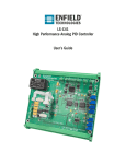
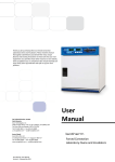
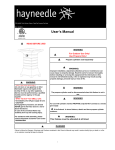
C1
Controller & Driver
User’s Guide
C1
User’s Manual
Page 1 of 12
Table of Contents
Warnings & Notices
2
Quick Start Procedure
3
Factory Default Settings
4
System Setup
Position
5
Force
5
Pressure
5
Flow
6
Wiring
7
Potentiometers/Tuning
8-9
Jumpers
10
Troubleshooting
11
© 2012 Enfield Technologies
As Enfield Technologies strives for continuous
improvement and dedication to product development,
specifications are subject to change
v20120816
WARNING: Installation and operation of electronic and high pressure
systems (fluids and compressed gas) involves risk including property
damage and personal injury or death. Users should be properly
trained or certified and take safety precautions.
C1
User’s Manual
Page 2 of 12
Warnings & Notices
WARNING:
Installation and operation of electric and high pressure systems (fluids and compressed gas) involves risk
including property damage and personal injury or death.
Installers and users should be properly trained or certified and take safety precautions. This product may cause
death, personal injury, or property damage if improperly used or installed.
The information in this document and other information from Enfield Technologies and its authorized
representatives are intended for use by persons having technical expertise in selecting and using these products.
Product owners (“you”) should analyze all technical and safety requirements of your specific application, including
the consequences of any possible failure, before selecting a product. This product may not be suitable for all
applications, such as those acting upon people. Suitability is solely your responsibility. Because the requirements
for each application may vary considerably, you are solely responsible for conducting any testing or analysis that
may be required to determine the suitability of the product for your application, and to ensure that all
performance, safety and warning requirements for your application are met.
Caution:
While the product is low voltage, it contains open-frame electronic components and care should be taken to prevent unintentional contact with the product to avoid damage to person or property.
The C1 is an electro-static sensitive device. Use appropriate electro-static discharge (ESD) procedures during handling and
installation.
Notice:
Use and purchase of this product is subject to Enfield Technologies’ Terms and Conditions of Sale and Use. Improper
installation or use voids warranty. Consult factory regarding special applications. Specifications are subject to change.
Reasonable efforts have been made to provide useful and correct information in this document, but this document may contain
errors and omissions, and it is subject to change.
Contact: Enfield Technologies
35 Nutmeg Drive
Trumbull, CT 06611 USA
+1 203 375 3100
+1 800 504 3334 toll free North America
[email protected]
www.enfieldtech.com
© 2012 Enfield Technologies
As Enfield Technologies strives for continuous
improvement and dedication to product development,
specifications are subject to change
v20120816
WARNING: Installation and operation of electronic and high pressure
systems (fluids and compressed gas) involves risk including property
damage and personal injury or death. Users should be properly
trained or certified and take safety precautions.
C1
User’s Manual
Page 3 of 12
Quick Start Procedure
1.
Configure Jumpers
a. Configure the left side of Jumpers 2 and 3 to select a command input of 0…10Vdc or 4…20mA
b. Configure the right side of Jumpers 2 and 3 to select a command input of 0…10Vdc or 4…20mA
c. Configure Jumper 1 to select control algorithm
2.
Wire Feedback
a. For 4…20mA signals: 4mA should correspond to the minimum feedback value and 20mA should
correspond to the maximum feedback value. Also, for 4…20mA signals, low side should connect to ground.
b. For 0…10V signals: 0V should correspond to the minimum feedback value and 10V should correspond to
the maximum feedback value
3.
Wire Command
4.
Wire Power
5.
Connect Pneumatic Lines
a. Connect valve ad shown in “system setup”
b. Inlet air should be dry (-40F dew point) non-lubricated air, non-flammable & non-corrosive dry gases (0.3
micron fine grade coalescing filter with 5 micron pre-filter) at 0-150psig.
6.
Tune System
a. Restore potentiometers to factory default settings
b. Tune System
7.
Troubleshooting
a. See “Troubleshooting”
b. Contact Enfield Technologies for additional help
© 2012 Enfield Technologies
As Enfield Technologies strives for continuous
improvement and dedication to product development,
specifications are subject to change
v20120816
WARNING: Installation and operation of electronic and high pressure
systems (fluids and compressed gas) involves risk including property
damage and personal injury or death. Users should be properly
trained or certified and take safety precautions.
C1
User’s Manual
Page 4 of 12
Factory Default Setting
Potentiometer
Factory Default Condition
Setting
RP1 – Proportional Gain
RP2 – Ramp Rate
RP3 – Minimum Feedback
RP4 – Maximum Feedback
Fully Counter Clockwise
Fully Counter Clockwise
Fully Counter Clockwise
Fully Clockwise
Proportional gain is zero
Command is not being ramped
No Adjustment to Minimum Position
No Adjustment to Maximum Position
Jumper
Factory Default Condition
Setting
J1 – Control Algorithm
Configuration #1
J2 (left side) - Command
J3 (left side) - Command
J2 (right side) - Feedback
J3 (right side) - Feedback
Jumper Off
Jumper Off
Jumper Off
Jumper Off
RP1 = Proportional Gain; RP2 = Ramp Rate
RP3 = Minimum Feedback; RP4 = Maximum Feedback
0…10V Command
0…10V Command
0…10V Feedback
0…10V Feedback
LED
Factory Default Condition
Setting
Power
Status
On
Off
Power is On
Not Status or Fault Indications
© 2012 Enfield Technologies
As Enfield Technologies strives for continuous
improvement and dedication to product development,
specifications are subject to change
v20120816
WARNING: Installation and operation of electronic and high pressure
systems (fluids and compressed gas) involves risk including property
damage and personal injury or death. Users should be properly
trained or certified and take safety precautions.
C1
User’s Manual
Page 5 of 12
Position or Force Control
Pressure Control
© 2012 Enfield Technologies
As Enfield Technologies strives for continuous
improvement and dedication to product development,
specifications are subject to change
v20120816
WARNING: Installation and operation of electronic and high pressure
systems (fluids and compressed gas) involves risk including property
damage and personal injury or death. Users should be properly
trained or certified and take safety precautions.
C1
User’s Manual
Page 6 of 12
Flow Control
© 2011 Enfield Technologies
As Enfield Technologies strives for continuous
improvement and dedication to product development,
specifications are subject to change
v20110311
WARNING: Installation and operation of electronic and high pressure
systems (fluids and compressed gas) involves risk including property
damage and personal injury or death. Users should be properly
trained or certified and take safety precautions.
C1
User’s Manual
Page 7 of 12
Wiring
Pin
1
2
3
4
5
6
7
8
Label
+Pwr
Gnd
M+
MCmd
Fbk
N/A
+10
Function
+12…24VDC, power supply connection
common (dc ground), connect to power supply common
Valve+ (brown)
Valve- (blue)
Command Input
Feedback Input
Not Used
+10Vdc Excitation
© 2011 Enfield Technologies
As Enfield Technologies strives for continuous
improvement and dedication to product development,
specifications are subject to change
v20110311
WARNING: Installation and operation of electronic and high pressure
systems (fluids and compressed gas) involves risk including property
damage and personal injury or death. Users should be properly
trained or certified and take safety precautions.
C1
User’s Manual
Page 8 of 12
Potentiometers/Tuning
much derivative can cause the system to undershoot
and “creep” into the target position or become
unstable.
Integral Gain – By adjusting the integral gain, the
user can reduce the steady state error of the system.
Integral gain be increased or decreased by turning
the potentiometer clockwise or counterclockwise,
respectively. Too little integral gain can result in
steady state error while too much integral gain can
cause oscillations and overshoot.
Ramp Rate – By adjusting the ramp rate, the user can
set the ramp rate of the command input to the
controller. The ramp rate be increased or decreased
by turning the potentiometer clockwise or
counterclockwise, respectively. A high ramp rate
results in a slower rise time while a lower ramp rate
results in a faster rise time.
The C1 has 4 potentiometers (RP1, RP2, RP3 and RP4)
which allow the user to adjust different gains depending on
jumper configuration. For instructions on how to switch
between configurations see the Jumper Configurations
section. A polymer non-conductive screwdriver is the
preferred method for adjusting the potentiometers. Care
should be taken not to allow metal screwdrivers to touch
other components on the board.
Minimum Feedback – By adjusting minimum
feedback, the user can offset the minimum feedback
value for the controller. For feedback sensor with a
minimum output greater than 0V or 4mA, this
adjustment should be used. The minimum feedback
be increased or decreased by turning the
potentiometer clockwise or counterclockwise,
respectively. For sensors that do not require any
offset, this potentiometer should be set fully counter
clockwise.
Proportional Gain –By adjusting the proportional gain,
the user can adjust the responsiveness of the system
to changes in command or feedback.
The
responsiveness of the system can be increased or
decreased by turning the proportional gain clockwise
or counterclockwise, respectively. A gain that is too
low can result in an unresponsive system while a
gain that is too high can cause the system to
become unstable.
Derivative Gain – By adjusting the derivative gain, the
user can set the damping applied to the system. This
damping can be increased or decreased by turning
derivative gain clockwise or counterclockwise,
respectively. Damping helps reduce overshoot and
smoothes out system performance. However, too
© 2011 Enfield Technologies
As Enfield Technologies strives for continuous
improvement and dedication to product development,
specifications are subject to change
v20110311
Maximum Feedback – By adjusting maximum
feedback, the user can offset the maximum feedback
value for the controller. For feedback sensor with a
maximum output less than 10V or 20mA, this
adjustment should be used. The maximum feedback
be increased or decreased by turning the
potentiometer clockwise or counterclockwise,
respectively. For sensors that do not require any
offset, this potentiometer should be set fully
clockwise.
WARNING: Installation and operation of electronic and high pressure
systems (fluids and compressed gas) involves risk including property
damage and personal injury or death. Users should be properly
trained or certified and take safety precautions.
C1
User’s Manual
Page 9 of 12
For a more detailed explanation of PID controls sell effects of increasing gains below.
Without Tuning
With Tuning
Effects of Increasing Gains
Parameter
Rise time
Overshoot
Settling time
Steady State Error
Proportional Gain
Decrease
Increase
Small change
Decrease
Integral Gain
Decrease
Increase
Increase
Eliminate
Derivative Gain
Small Change
Decrease
Decrease
None
Effects of Increasing Ramp Rate
© 2011 Enfield Technologies
As Enfield Technologies strives for continuous
improvement and dedication to product development,
specifications are subject to change
v20110311
Effects of Decreasing Ramp rate
WARNING: Installation and operation of electronic and high pressure
systems (fluids and compressed gas) involves risk including property
damage and personal injury or death. Users should be properly
trained or certified and take safety precautions.
C1
User’s Manual
Page 10 of 12
Configure Potentiometers
Jumper Configurations
To configure jumpers remove lid for access
Config #1
Config #2
J1
To switch bewtween control configurations
1. Remove air from the system.
2. Turn power off.
3. Move jumper to desired confiuration.
4. Turn power back on.
5. Upon powering, the red LED will be blinking quickly.
6. Turn all potentiometers fully counter clockise.
7. Grenn LED will blink four times slowly. This will
indicate that the driver has switched configurations.
Configure Command for 0…10Vdc
J2
J3
Configure Command for 4…20mA
J2
J3
Configure Feedback for 0…10Vdc
J2
J3
Configure Feedback for 4…20mA
J2
J3
© 2011 Enfield Technologies
As Enfield Technologies strives for continuous
improvement and dedication to product development,
specifications are subject to change
v20110311
WARNING: Installation and operation of electronic and high pressure
systems (fluids and compressed gas) involves risk including property
damage and personal injury or death. Users should be properly
trained or certified and take safety precautions.
C1
User’s Manual
Page 11 of 12
Troubleshooting
Symptom
Probable Causes
Corrective Action
System Totally Unresponsive
Power Not Applied
Air Off
Proportional Gain too Low
Signal Wiring
Apply power, check all power wiring
Turn air on
Turn Proportional Gain Clockwise
Verify signal wiring for command and feedback; also verify
mechanical system polarity
Verify all Wiring
Proportional Gain too Low
Turn Proportional Gain Clockwise
Power Supply Voltage not Stable
Check power wiring; change power supply
No Feedback Signal
Connect Feedback Signal
Verify all wiring is as shown in application examples and as
described in the “System Setup” section of this document
Inverted Polarity
System Mildly Responsive or
Sluggish
System ‘Pegs’ or ‘Rails’
Feedback Connected Improperly
System Fails to Converge or is
Inaccurate
System Oscillates
System ‘Buzzes’
Incorrect Wiring
Mechanical System
Proportional Gain too Low
Increase Integral Gain
Maximum Feedback Set Incorrectly
Minimum Feedback Set Incorrectly
Air Leaks
Valve Sticking
Proportional Gain too High
Integral Gain too High
Valve Oversized for System
Input Signal Noise (possibly 60Hz)
Input Signals not connected
DC Common not connected
High Pitched Tone or Whine
from Valve
Dither
Verify all wiring is as shown in application examples and as
described in the “Installation” section of this document
Consult Factory for Suggestions
Turn Proportional Gain Clockwise
Turn Integral Gain Clockwise
Adjust the Maxiium Feedback Potentiometer
Adjust the Maxiium Feedback Potentiometer
Insure there are no air leaks in the system
Insure that inlet air meets valve specifications.
Turn Proportional Gain Counter Clockwise
Turn Integral Gain Counter Clockwise
Consult Factory
Verify that large or high power machinery is not operating
nearby. Also, verify input signal integrity by examining the
signal with an oscilloscope.
Verify all wiring as shown in the “System Setup” section of
this document
Verify all DC common connections
This is an artifact of the built-in dither and is intended to
keep the electro-mechanical device in constant motion.
Warranty: This product is covered by a 1 year Enfield Technologies limited warranty. Contact Enfield Technologies or visit website for more details.
Notice: Use and purchase of this product is subject to Enfield Technologies’ Terms and Conditions of Sale and Use. Improper installation or use voids warranty. This product may not
be suitable for all applications, such as those acting upon people, and suitability is solely the buyer’s responsibility. Consult factory regarding special applications.
© 2011 Enfield Technologies
As Enfield Technologies strives for continuous
improvement and dedication to product development,
specifications are subject to change
v20110311
WARNING: Installation and operation of electronic and high pressure
systems (fluids and compressed gas) involves risk including property
damage and personal injury or death. Users should be properly
trained or certified and take safety precautions.