1
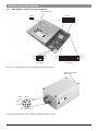
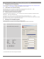
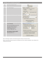
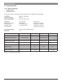
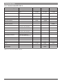
WZ LSA 4-3
User manual
��
�
�
��
��
�� �
��
��
��
��������
���� �
�� � ��
�������
���� ���
� ��
��
�
Table of contents
1.
2.
3.
Safety precautions ..................................................................................................................3
General instructions ................................................................................................................3
General product description ...................................................................................................4
3.1
Description of device-specific features ..........................................................................................................4
3.2
Designation of the functional elements..........................................................................................................5
3.3
Interfaces at the unit .......................................................................................................................................6
3.3.1 Pin configuration of the 6-pole user interface (IP65 housing) ....................................................................6
3.3.2 Pin configuration of the 20-pole user interface (PCB version) ...................................................................6
4.
Putting the unit into operation.................................................................................................8
4.1
4.2
5.
6.
Initial state of the unit after starting ................................................................................................................8
Memory selection at the user interface ..........................................................................................................8
Settings at the terminal program ............................................................................................8
Settings at the unit ................................................................................................................10
6.1
Entering software commands ......................................................................................................................10
6.1.1 Displaying the version number .................................................................................................................10
6.1.2 Displaying the serial number of the unit ...................................................................................................10
6.1.3 Displaying the command by means of echo ............................................................................................10
6.1.4 Setting the output mode ...........................................................................................................................11
6.1.5 Displaying the number of the current memory .........................................................................................11
6.1.6 Selecting a memory (software selection) .................................................................................................11
6.1.7 Selecting the memory set by the hardware ..............................................................................................11
6.1.8 Displaying the analogue measuring signal RSSI (input level) .................................................................11
6.1.9 Setting software handshake......................................................................................................................12
6.1.10 Resetting the unit to factory setting ..........................................................................................................12
6.2
Factory setting ..............................................................................................................................................12
7.
8.
Maintenance..........................................................................................................................12
Troubleshooting ....................................................................................................................13
8.1
8.2
8.3
8.4
Outputs in normal output mode...................................................................................................................13
Outputs in extended output mode ...............................................................................................................13
Information regarding troubleshooting ........................................................................................................13
Explaining the error code in extended output mode ...................................................................................14
9. Service and repair .................................................................................................................15
10. Technical data .......................................................................................................................16
10.1
10.2
Scope of delivery..........................................................................................................................................16
Technical data WZ LSA 4-3 ..........................................................................................................................17
11. Circuit diagrams ....................................................................................................................18
11.1
11.2
11.3
Standard wiring of the user interface ...........................................................................................................18
User interface at data transmission..............................................................................................................18
User interface at speech transmission.........................................................................................................19
12. Time lapse diagrams of the unit............................................................................................19
12.1
12.2
12.3
12.4
Typ. time response for receive mode as function of the received signal ....................................................19
Typ. time response for receive mode as function of the channel................................................................20
Typ. RSSI response over input level and temperature ................................................................................20
Typ. frequency response of the receiver......................................................................................................21
13. Dimensions............................................................................................................................22
14. Conformity.............................................................................................................................23
15. Glossary ................................................................................................................................23
2
Safety precautions / General instructions
1.
Safety precautions
ATTENTION!
•
Do not operate the units in rooms with explosive atmosphere, damp environments or rooms with
aggressive air or increased electromagnetic requirements.
•
Mind the instructions for putting the unit into operation.
•
Fuse the unit at the voltage supply input UB_IN of the user interface by means of a fuse
(min. 250 mA, max. 1 A).
•
In case there is a danger of touching conductive parts due to improper use of the unit, the power supply
has to be disconnected immediately.
•
Do not open the unit, only permit repairs by the manufacturer.
ESD protection measures
Comply with the ESD protection measures according to DIN EN 61340-5-1/2 when opening
the unit (potential equalization between body and ground of the unit via high-value resistance
(approx. 1 MOhm) e. g. over a usual wrist band.).
Read this user manual carefully to be ably to use the wealth of features of your new WZ LSA 4-3.
You can also find further information on our website http://www.fmncom.com.
2.
•
General instructions
The compliance with the operating instructions and the instructions for putting the device into operation
is also part of the intended use. Every other use is considered as not to be intended.
The manufacturer assumes no liability for damages resulting from such use.
•
All connection cables have to be equipped with an earth-connected shielding.
The antenna connection cable has to be equipped with a wave impedance of 50 Ohm.
•
The manufacturer recommends to mount devices in PCB version into a metal housing.
•
Corresponding mechanisms are to be used for the detection of single bit errors during a data
transmission (e. g. protocol with creation of check sum).
Information regarding the used trademarks
Microsoft® and Windows® are registered trademarks of the Microsoft Corporation. All other trademarks and product
names are trademarks or registered trademarks of the relevant companies.
Copyright
All rights reserved. Duplication of this user manual or parts thereof by any reproduction method whatsoever is not
permitted without prior permission of the manufacturer.
Amendments may be published without prior notification.
Notwithstanding the above declaration, the manufacturer accepts no liability for errors in these instructions or their
consequences.
3
General product description
3.
3.1
General product description
Description of device-specific features
The unit WZ LSA 4-3 is a light signalling receiver with synthesizer which has been designed for data as well as for
voice operation in the 4 m band. Because of its compactness, it is suitable for the integration into data systems
where it depends on high data rates over greater distances.
Data rates up to 9600 bps are possible in connection with a GMSK modem and up to 2400 bps by means of a
FFSK modem.
The unit complies with the requirements of the VDV guideline (Verband Deutscher Verkehrsunternehmen Association of German transportation companies) and may be used for applications of this type anytime.
Numerous functions are part of the advanced features of the unit WZ LSA:
•
Settings over an extended command interpreter by means of terminal program.
•
512 memories whose parameters are adjustable separately via software.
•
Selecting the memories by means of hardware or software.
•
Debounce time for hardware selection lines.
The time can be adjusted via software.
•
Displaying the analogue RSSI value (field strength value) via a terminal program.
The measuring signal of the analogue RSSI value is available at the user interface.
•
Displaying of error conditions of the unit.
The time of the display is adjustable via software. (An LED with series resistor can e. g. be connected at the
user interface. You get a detailed description in chapter 8.3 Information regarding troubleshooting.)
•
File download from PC to the WZ LSA unit for setting the parameters.
•
•
File upload from the WZ LSA unit to the PC for displaying the parameters by means of terminal program.
File download from the PC to the WZ LSA unit for loading new WZ LSA software.
Adjustable parameters of the program software:
•
Setting the output mode (to normal or extended).
•
Setting the software handshakes to Xon / Xoff or NO.
•
Displaying the input instructions by means of command echo.
•
Setting the RS232 baud rate from 1.2 kBaud to 115 kBaud.
•
Resetting the WZ LSA unit to factory setting.
•
Setting the waiting time of the output ERROR of the user interface.
4
General product description
3.2
Designation of the functional elements
������������������
���
����������
��� �
��� ��
�����
�����
�����
�����
�����
������
������
�����
�����
�������
��������������
������
��������������
Figure 3-1: Designation of the functional elements (PCB version)
������������������
����������
�����
�����
�����
�
�����
�
�
� �
�����
�
��
��
��
��
�
��
�
�
�
��������
���� �
�� � ��
�������
���� ���
�
��
��
�
��
�
�
�
�
�
����������������
Figure 3-2: Designation of the 6-pole user interface (IP65 housing)
5
General product description
3.3
3.3.1
PIN
1
Interfaces at the unit
PIN configuration of the 6-pole user interface (IP65 housing)
Assignment
UB_IN
Function
Input
Interior wiring
���������������������
Description
���
Voltage supply 9 ... 15 VDC
��
Ground
3
NF_OUT
Output,
analogue
Ground lead
������
���������
���
not used
5
RSSI
Output,
analogue
��������
����
����
6
GND
Signal strength: the received field strength
can be determined by measuring the analogue
voltage.
���
���
4
���
����
���
Demodulated NF signal without
DC voltage components (DC decoupled)
���
GND
�
2
Ground
Ground lead
Table 3-1
3.3.2
PIN
1
PIN configuration of the 20-pole user interface (PCB version)
Assignment
UB_IN
Function
Input
Interior wiring
���������������������
Description
���
Voltage supply
��
2
GND
Ground
3
RSSI
Output,
analogue
Ground lead
��������
����
4
RX_BB
Output,
analogue
���
���
����
Signal strength: the received signal strength
can be determined by measuring the analogue
voltage.
��������
�����
Demodulated signal without filtering
������
Data output with DC voltage components
��
5
AF_INT
Output,
analogue
���������
��
6
6
reserved
7
DIL7
not wired
Input,
digital
see PIN 12
Memory selection bit 6,
valency 26 see also chapter
4.2 Memory selection at the user interface
General product description
PIN
Assignment
Function
8
DIL8
Input, digital
9
RS232_
OUT
Output, active
HIGH
Interior wiring
Description
see PIN 12
Memory selection bit 7,
valency 27 see also chapter 4.2 Memory selection at the user interface
���������
��������������
Data output to the serial PC interface
log. level see table 3-1
1)
2)
Data input from the serial PC interface
log. level see table 3-1
1)
3)
��
10
RS232_IN
Input, active
HIGH
��������
��������������
��
Input, digital
12
DIL1
Input, digital
see PIN 12
Memory selection bit 8,
valency 28 see also chapter 4.2 Memory selection at the user interface
Memory selection bit 0,
valency 20 LSB see also chapter 4.2 Memory
selection at the user interface
log. level see table 3-1
���
DIL9
���
11
����
��������������
������
��
13
DIL2
Input, digital
see PIN 12
Memory selection bit 1,
valency 21 see also chapter 4.2 Memory selection at the user interface
14
DIL3
Input, digital
see PIN 12
Memory selection bit 2,
valency 22 see also chapter 4.2 Memory selection at the user interface
15
DIL4
Input, digital
see PIN 12
Memory selection bit 3,
valency 23 see also chapter 4.2 Memory selection at the user interface
16
DIL5
Input, digital
see PIN 12
Memory selection bit 4,
valency 24 see also chapter 4.2 Memory selection at the user interface
17
DIL6
Input, digital
see PIN 12
Memory selection bit 5,
valency 25 see also chapter 4.2 Memory selection at the user interface
VDD
Output
18
���
�����������������
��
Output,
digital
This output conducts for approx. 2 seconds
LOW level after faulty actions
rest state: HIGH
signal state: LOW for approx. 2 seconds
���
ERROR
��
19
Voltage supply for external modules signal level:
5 VDC ±5 % without load; 4.5 VDC ±5 % at
max. load of 5 mA
4)
�����
���������������
��
20
1)
2)
3)
4)
GND
Ground
Ground leads for all inputs and outputs
A level converter (e. g. MAX232) can be connected to these pins. A data exchange to the serial PC interface can be
established.
Connect the output of the level converter to be connected with PIN 2 (RXD) at 9-pole interface or with PIN 3 (RXD) at
25-pole interface.
Connect the input of the level converter to be connected with PIN 3 (TXD) at 9-pole interface or with PIN 2 (TXD) at 25-pole
interface.
The display time can be adjusted via software.
7
Putting into operation / Settings at the terminal program
4.
Putting the unit into operation
For connecting the interfaces, use chapters 3.2 Designation of the functional elements and 3.3 Interfaces at the
unit. In chapter 11. Circuit diagrams, appropriate application circuits are given.
4.1
Initial state of the unit after starting
After starting the unit, the set memory corresponds to the selected switch position DIL1 ... DIL9.
The other parameters correspond to the delivery status of the unit.
The switch DIL0 is reserved and may not be changed.
4.2
Memory selection at the user interface
The WZ LSA 4-3 has 512 memories (0 ... 511). The memory to be used for the operation is selected over the
switch DIL1 ... DIL9 (see configuration list).
The selection of the memory can also be effected by the wiring of the inputs PIN 7, 8, 11 ... 17 with
DIP switches or by the connection of the inputs with the outputs of a microcontroller. The switches DIL1 to DIL9
have to be set to the memory 511 (all DIP switches to OFF).
5.
Settings at the terminal program
The parameterisation can be carried out with any terminal program.
The manufacturer recommends to use the program Hyperterminal from Microsoft® Windows.
��
����� ������� �������������
��
��� ��� ��� � ��������� �� ��� �������� ��
����� ��� �� ��� ���� �� ���������
��
���� ��� ��������� ��������
���� �����
���� �����
�������
���� �����
���� ��������
����
�����
���� ����
� ���
�����
� ���
���� ����
��������� ���� ��
��������� ���� ��
1) The ASCII-HEX values can be changed via software.
8
Settings at the terminal program
��
����� �� ��� ��� ����������������
��
������ ����������������
��
����� �� ��� ������ ����������������������
��
�� ��� ������� ������ ���������������������
������ ��� ����������
��������������� ������ �������������
�� ��������� ������ ����� ��� ��� �
�� ����������� ������� ����� ��� �
�� ������������������ � ���
�� ������������������� � ���
��������������� ������ ����������
�� ���� ������� �������������� ��� �
�� ��������� ������ �� ��� �
After confirming the options, the terminal program is ready to send and receive.
When using another terminal program, the settings have to be made like explained in the example of the
Hyperterminal program.
9
Settings at the unit
6.
Settings at the unit
6.1
Entering software commands
Command
syntax
Range of
values
V
Description
Chapter
Displaying the version number
6.1.1
N
ASCII
16-digit
Displaying the serial number of the unit
6.1.2
EX
X = 0 ... 1
Echo of the commands (X = 0 -> no echo, X = 1 -> echo)
6.1.3
?EX
X = 0 ... 1
Output mode (X = 0 -> normal, X = 1 -> extended) (service command)
6.1.4
?SM
0 ... 511
Outputting current memory number (service command)
6.1.5,
6.1.6
SMX
X = 0 ... 511
Software selection: selecting the memory and the appropriate
RX channel
6.1.6
Hardware selection: selection of the memories depends on the current
hardware setting
6.1.7
SM
A0
0 ... 1023
Output of the analogue measuring signal RSSI (input level)
6.1.8
XX
X = 0 ... 1
Xon / Xoff - protocol: X = 0 -> deactivating, X = 1 -> activating
6.1.9
Reset to factory setting
6.1.10
F
Table 6-1: Short overview command syntax
Please use the short overview for the following command explanations. A gradual execution of the given examples
accelerates the process of learning all the commands quickly.
6.1.1
Displaying the version number
Example 1
Input
Output (example)
Displaying the name of the unit and the version
V +ENTER
WZ LSA 4-3 V2.00 01
Short description of the version:
WZ
LSA 4-3
VX.XX
XX
Product family
Model
Version number e. g. V2.00
Parameter version
6.1.2
Displaying the serial number of the unit
Example 1
Input
Output (example)
Displaying the serial number of the unit
N +ENTER
SN: 00000000SO000001
Example 1
Input
Output
Activating the command echo
E1 +ENTER
OK
6.1.3
Displaying the command by means of echo
An entered command is sent back to the PC interface by the unit for the control of the input.
Example 2
Input
Output
Deactivating the command echo
E0 +ENTER
E0
OK
10
Settings at the unit
6.1.4
Setting the output mode
Example 1
Input
Output
Activating the extended output mode
see 8.2 Outputs in the extended output mode
?E1 +ENTER
OK
Example 2
Input
Output
Activating the normal output mode
see 8.1 Outputs in normal output mode
?E0 +ENTER
OK
Example 1
Input
Output (example)
Setting the memory 2 by means of the selection switch
(see 4.2 Memory selection at the user interface)
displaying the memory number
?SM +ENTER
Memory: 00002 H
6.1.5
Displaying the number of the current memory
The displayed H in this output indicates that the current memory was set by means of hardware selection. In case
of software selection, an S appears in the output.
6.1.6
Selecting a memory (software selection)
Example 1
Input
Output (example)
Selecting the memory 3
SM3 +ENTER
OK
As a check: Displaying the memory number
?SM +ENTER
Memory: 00003 S
Example 1
Input
Output (example)
Deactivating the software selection
SM +ENTER
OK
As a check: Displaying the memory number
?SM +ENTER
Memory: 00002 H
6.1.7
Selecting the memory set by the hardware
see 4. Putting the unit into operation
6.1.8
Displaying the analogue measuring signal RSSI (input level)
For determining the input level in dBm, proceed as follows:
Example 1
Input
Output (example)
Inquire the indicated value RSSI
A0 +ENTER
A0
RSSI = 00512
For determining the input level in dBm, proceed as follows:
1.
Calculate the RSSI voltage in volt
��������������� ��� � � ��������������������
����
2.
Determine the input level in dBm by means of figure 12-3: Typ. RSSI response over input level and temperature.
11
Settings at the unit / Maintenance
6.1.9
Setting software handshake
Example 1
Input
Output
Deactivating protocol Xon / Xoff (no protocol)
X0 +ENTER
OK
Example 2
Input
Output
Activating protocol Xon / Xoff
X1 +ENTER
OK
Example 1
Input
Output
Setting the factory setting of the unit
see 4.1 Initial state of the unit after starting
F +ENTER
OK
6.1.10 Resetting the unit to factory setting
6.2
Factory setting
Setting
Default value
Single command
Xon / Xoff protocol
activated
X1
Command echo
deactivated
E0
Waiting time for error outputs (PIN 20 ERROR)
w = 1.3 s
Parameter change possible by the
manufacturer
x = 5.12 ms
Parameter change possible by the
manufacturer
normal
?E0
����� ������ ������ � � � � ���� ��
�
����
���
���� ��
Debounce time delay selection line
Changes in state at the selection lines < than x ms are
not recognized as signal change.
Output mode
Table 6-2: Default values of the factory setting
7.
Maintenance
The unit can be operated without maintenance.
12
Troubleshooting
8.
Troubleshooting
8.1
Outputs in normal output mode
The WZ LSA unit is connected with the terminal program by means of a serial interface.
Output
Description
OK
Command is valid and was executed correctly
ERROR
Command is valid, but could not be executed correctly
CMD-ERROR
Command is invalid
Table 8-1: Output mode normal (“?E0“)
8.2
Outputs in extended output mode
The WZ LSA unit is connected with the terminal program by means of a serial interface.
Input
Activating the extended output mode
Output
Range
of values
Output
?E1 +ENTER
Description
OK
Command is valid and was executed correctly
CMD-ERROR
Command is invalid
RX OK
Programming RX channel successful
ERROR XX
XX = 00 ... FF
Command is valid, but could not be executed correctly
RX ERROR XX
XX = 00 ... FF
Error at RX programming
Table 8-2: Output mode extended (“?E1“)
see 8.4 Explaining the error code in extended output mode
8.3
Information regarding troubleshooting
An LED with series resistor can be connected at the output ERROR (19) of the user interface for displaying error
conditions. The output signal is LOW in case of an error.
Error description
Display
Remedy
The ERROR output is activated for 1.3 seconds (factory setting) 1).
a
RX programming faulty
ERROR
see 9. Service and repair
b
Memory contains a faulty parameter
ERROR
see 9. Service and repair
1)
The operating time for error outputs can be set by means of parameters (factory setting 1.3 s).
13
Troubleshooting
8.4
Explaining the error code in extended output mode
For troubleshooting, inform the customer service of the manufacturer of the displayed output with the error code.
The customer service will give you a specified instruction to clear the fault.
XX
Meaning
Output ERROR - LED
RS232 interface
01
Communication error
on: active LOW 1)
02
Communication error
on: active LOW 1)
03
Communication error
on: active LOW 1)
04
Communication error
on: active LOW 1)
Frequency programming
05
Error at frequency programming
Remedy:
Programm correct values
on: active LOW 1)
Parameter memory
0A
Error in the parameter memory
off
0B
Error in the parameter memory
off
0C
Error in the parameter memory
off
0D
Error in the parameter memory
off
0E
Error in the parameter memory
off
0F
Error in the parameter memory
off
10
Error in the parameter memory
off
11
Error in the parameter memory
off
12
Error in the parameter memory
off
Parameter memory
16
Error in the parameter memory
on: active LOW 1)
17
Error in the parameter memory
off
18
Parameter faulty
on: active LOW 1)
Parameter memory
1E
Memory in the parameter memory not found
on: active LOW 1)
1F
Memory in the parameter memory not found
Input value bigger than existing entries
off
Table 8-3: Short overview of error messages of the unit
1)
14
The waiting time for error outputs (ERROR-LED) is adjustable by means of parameter (factory setting 1.3 s).
Service and repair
9.
Service and repair
In case the message ERROR appears repeatedly, the manufacturer recommends to proceed as follows:
1.
Use options as described in chapter 5. Settings
at the terminal program
2.
In the menu Transmission in the hyperterminal,
select the point „Text aufzeichnen“
3.
Select text file or create new text file
The content of the terminal window is registered in the
text file after terminating the program.
4.
Activating the extended output mode ?E1 +ENTER
5.
Process the commands of the points 6 to 26
step by step
6.
V +ENTER
7.
N +ENTER
9.
?SM +ENTER
OK is displayed
13. Ui +ENTER
14. Ue0 +ENTER
15. Ue1 +ENTER
16. Ue2 +ENTER
17. Ue3 +ENTER
18. Ue4 +ENTER
19. Ue5 +ENTER
20. Ue6 +ENTER
21. Ue7 +ENTER
22. MD +ENTER
23. MR +ENTER
24. V +ENTER
25. Provoking of the error messages that are
appearing repeatedly.
26. Send the text file to the customer service of
the manufacturer.
The unit WZ LSA may only be repaired by the manufacturer.
In case the unit has a malfunction, please see chapter 8. Troubleshooting. In case the malfunction is not
described, please contact the manufacturer and send him a short description of the malfunction. Please use the
overview at the beginning of this chapter to specify the description.
Errors may only be removed by authorised specialists.
15
Technical data
10. Technical data
10.1 Scope of delivery
•
•
unit WZ LSA 4-3
configuration list
If not given otherwise, the limits of the ETSI EN 300 113 and ETSI EN 301 489 apply.
HF modes:
Channel spacing:
Type of modulation:
Simplex, semiduplex
20 kHz
F1D, G1D, F2D, G2D
Interfaces:
Antenna connection:
Power supply:
LF/ RSSI output:
User interface:
Housing IP65
TNC socket
LF socket U-79/U
LF socket U-79/U
HF channel setting:
Memories:
via DIL switch / RS232 interface
512
Technical data general
Remarks
PCB version
2-pole SIL connector
6-pole SIL connector
6-pole SIL connector
20-pole SIL connector
Min. value
Typical value
Dimensions PCB version
L x W x H (in mm)
94 x 68 x 14 mm
Dimensions housing version
L x W x H (in mm)
125 x 80 x 58 mm
Weight PCB version
approx. 60 g
Weight housing version
approx. 600 g
Max. value
Operating temperature
-25 °C
75 °C
Storage temperature
-40 °C
80 °C
Supply voltage
Frequency range
Frequency tolerance
Table 10-1: General technical data
16
9V
12.5 V
15 V
68.000 MHz
87.500 MHz
-1.0 kHz
+1.0 kHz
Technical data
10.2 Technical data WZ LSA 4-3
Technical data in general
Min. value
Typical value
Max. value
-102 dBm
-107 dBm
-110 dBm
Co-channel rejection
-12 dB
-3 dB
0 dB
Adjacent channel selection
70 dB
72 dB
75 dB
Blocking
84 dB
> 100 dB
Spurious rejection
70 dB
> 100 dB
Intermodulation rejection
65 dB
66 dB
Sensitivity
Notes
Sensitivity BER 10-2
Data
Spurious emission
LF voltage
-60 dBm
at 600 Ohm at -85 dBm
HF level 2.1 kHz deviation
Data
Distortion factor
-1.5 dBm
1.5 dBm
2.0 %
4.0 %
at 600 Ohm at -85 dBm
HF level 2.1 kHz deviation
Data
LF frequency response
0.0 dBm
at 600 Ohm relating to
1 kHz modulation frequency
80 Hz
-1.0 dB
0.0 dB
1.0 dB
100 Hz
-1.0 dB
0.0 dB
1.0 dB
300 Hz
-1.0 dB
0.0 dB
1.0 dB
1 kHz
-1.0 dB
0.0 dB
1.0 dB
3 kHz
-5.5 dB
-4.0 dB
-2.0 dB
IF bandwidth
15 kHz
Table 10-2: Technical data WZ LSA 4-3
17
Circuit diagrams
11. Circuit diagrams
J2-2
NF_OUT
J2-3
GND
J2-4
RSSI
J2-5
GND
J2-6
UB_IN
GND
RSSI
RX_BB
AF_INT
VPP_MCLR
DIL7 PCLOCK
DIL8 PDATA
RS232_OUT
RS232_IN
DIL9
DIL1
DIL2
DIL3
DIL4
DIL5
DIL6
VDD
ERROR
GND
J1-1
J1-2
J1-3
J1-4
J1-5
J1-6
J1-7
J1-8
J1-9
J1-10
J1-11
J1-12
J1-13
J1-14
J1-15
J1-16
J1-17
J1-18
J1-19
J1-20
+12V
100n
100n
16 1
Vcc C14
11
T1
10
3 2
C1- V+
7
T2
12
13
R1
9
V- C26 5
J3-1
J3-6
J3-2
J3-7
J3-3
J3-8
J3-4
J3-9
J3-5
14
R2
C2+ GND
4 15
8
RXD
RTS
TXD
CTS
GND
MAX232ACSE
RS232 interface
J2-1
GND
100n
UB_IN
100n
user interface
11.1 Standard wiring of the user interface
100n
A
K
+5V
1k5
Figure 11-1
The user interface of the WZ LSA 4-3 is wired with a interface for the parameterisation of the software via a driver
module MAX232. A light emitting diode LED with series resistor for the error indication is connected at the output
ERROR.
11.2 User interface at data transmission
+12V
J2-2
NF_OUT
J2-3
GND
J2-4
RSSI
J2-5
GND
J2-6
UB_IN
GND
RSSI
RX_BB
AF_INT
VPP_MCLR
DIL7 PCLOCK
DIL8 PDATA
RS232_OUT
RS232_IN
DIL9
DIL1
DIL2
DIL3
DIL4
DIL5
DIL6
VDD
ERROR
GND
J1-1
J1-2
J1-3
J1-4
J1-5
J1-6
J1-7
J1-8
J1-9
J1-10
J1-11
J1-12
J1-13
J1-14
J1-15
J1-16
J1-17
J1-18
J1-19
J1-20
+5V
AF_OUT
AF_IN
10K
GND
+
-
LM2580
TXD
Modem
TXC
RXD
RXC
DCD
microcontroller
J2-1
GND
10K
UB_IN
2k2
user interface
+5V
Figure 11-2
In addition to the standard wiring of the user interface of the WZ LSA 4-3, a modem with integrated FFSK or GMSK
modulation can be connected at the data transmission. The modem is the interface to a microcontroller or to a
computer.
18
Circuit diagrams / Time lapse diagrams
11.3 User interface at speech transmission
+12V
NF_OUT
J2-3
GND
J2-4
RSSI
J2-5
GND
J2-6
+
100n
J1-1
J1-2
J1-3
J1-4
J1-5
J1-6
J1-7
J1-8
J1-9
J1-10
J1-11
J1-12
J1-13
J1-14
J1-15
J1-16
J1-17
J1-18
J1-19
J1-20
LM386-M1
loudspeaker
+
-
10uF
8 Ohm
47n
UB_IN
GND
RSSI
RX_BB
AF_INT
VPP_MCLR
DIL7 PCLOCK
DIL8 PDATA
RS232_OUT
RS232_IN
DIL9
DIL1
DIL2
DIL3
DIL4
DIL5
DIL6
VDD
ERROR
GND
+10,5V
100n
J2-2
100n
J2-1
GND
10K
UB_IN
10R
user interface
+5V
voltmeter
100uA
+
LM258D
33K
field strength output
Figure 11-3
In addition to the standard wiring of the user interface of the WZ LSA 4-3, a loudspeaker can be connected for the
speech transmission. A voltmeter at the output RSSI is used for measuring the field strength.
12. Time lapse diagrams of the unit
12.1 Typ. time response for receive mode as function of the received signal
approx. 24 ms
receiver HF
first channel
approx. 24 ms
-60 dBm
-130 dBm
ca. +3 V
RSSI
0V
<2 ms
+2.5 V
receiver NF
data output
receiver NF
voice output
-2.5 V
approx. 3 ms
approx. 17 ms
+2.5 V
-2.5 V
Figure 12-1
19
Time lapse diagrams
12.2 Typ. time response for receive mode as function of the channel
����
��
��
� ���������������
����
� ���������������
���
�������������������������������������������������
�������
�����������
��������������
��������
������������
�������������
�������������
����
����
���
�������������
������
�����������
�����������
������
�������������
������
�����������
������������
������
Figure 12-2
12.3 Typ. RSSI response over input level and temperature
�
���
���� ����� �� �
�
���
��� ��
�� ��
�
�� ��
���
�
���
�
���� ���� ���� ���� ���� ���
���
���
���
����� ����� �� ���
Figure 12-3
20
���
���
���
���
���
Time lapse diagrams
12.4 Typ. frequency response of the receiver
5
relative level in dB
0
-5
-10
Daten
data 775 mV
-15
-20
-25
10,00
7,00
5,00
3,00
2,00
1,50
1,00
0,70
0,50
0,30
0,20
0,15
0,10
0,07
0,05
-35
0,03
-30
frequency in kHz
Figure 12-4: Frequency response at 2.4 kHz frequency deviation (at 775 mVeff at data output)
21
Dimensions
�������
�������
13. Dimensions
�����
�������
�������
�������
������
�����
�������
������
�������
�����������������������
������������
��������������������
�����
������
�������
�������
��������
����
Figure 13-1: Dimensions PCB version
�����
�����������������������
������������
��������������������
Figure 13-2: Dimensions in IP65 housing
22
�����
������
Conformity / Glossary
14. Conformity
Herewith, the FMN communications GmbH declares that the unit WZ LSA 4-3 complies with the essential
requirements and the other relevant provisions of the directive 1999/5/EG (R&TTE directive).
The unit WZ LSA 4-3 can be operated in the countries of the European Union (EU). Outside of the EU, the national
regulations of the respective country apply.
The complete declaration of conformity can be downloaded in the Internet under http://www.fmncom.com.
15. Glossary
4 m band
Mobile radio 4 m band (private mobile, BOS radio, marine radio service) 68 MHz - 87.5 MHz
ASCII
American Standard Code for Information Interchange
Download
Programmes or files are transferred to the radio unit during a download.
EEPROM
Electrical Eraseable PROM
ETS
European Telecommunication Standard
LED
Light Emitting Diode
LSA
Light Signalling Receiver
LSB
Least Significant Bit
MSB
Most Significant Bit
RS232
Recommanded Standard 232 - standardised serial interface
RSSI
Receiver Signal Strength Indicator - acquisition of the radio receiving field strength
RX
Receiver
RXD
Receive Data
Simplex
Unidirectional data transmission (from transmitter to receiver)
Software handshake
Communication protocol that controls the data flow over the serial interface between
computer and modem.
Control characters (Xon ASCII-HEX 0x11 / Xoff ASCII-HEX 0x13) that are added to the
data stream are used to stop or start the data flow.
Squelch
Controller for muting
TXD
Transmit Data
Upload
Programmes or files are transferred to the computer during an upload.
VCO
Voltage Controlled Oscillator
VDV
Verband Deutscher Verkehrsunternehmen (Association of German transportation
companies)
23
For the protection of the environment!
Printed on paper bleached without chlorine with a maximum waste paper content of 50 %.
FMN communications GmbH
Grimmelallee 4
99734 Nordhausen / Germany
P. O. Box 10 04 65
99724 Nordhausen / Germany
Phone:
Fax:
Email
Internet
+49 (36 31) 56-34 41
+49 (36 31) 56-32 24
[email protected]
http://www.fmncom.com
Subject to change.
WZ LSA 4-3: 8201.3.0070.01
Edition: 07/07 (1112-0928)