1
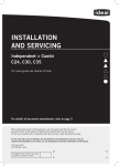
SERVICING
49flame detection electrode replacement
1. Refer to Frame 43.
Flame Detection Electrode
2. Remove the burner. Refer to Frame 46.
3. Unplug the flame detection lead from the
electrode.
4. Remove the 2 screws retaining the detection
electrode.
5. Remove the electrode.
6. Fit the new flame detection electrode, using the
new gasket supplied.
7. Reassemble in reverse order.
8. Check the operation of the boiler. Refer to
Frames 32 & 33.
e
dg
te
gh
i
a
Str
m
.5m
50 Spark generator replacement
51 gas control valve replacement
1. Refer to Frame 43.
2. Disconnect the leads from the spark generator.
3. Remove the M5 screws securing the spark generator
to the boiler chassis.
4. Fit the new spark generator and re-assemble in
reverse order ensuring the two earth leads are
correctly replaced.
5. Check operation of the boiler. Refer to Frames 32 & 33.
1. Refer to Frame 43.
2. Unplug the electrical lead connection from the gas control
valve and disconnect the earth wire.
3. Undo the union nut on the outlet of the gas control valve.
4. Undo the gas inlet pipe union at the inlet to the gas control valve.
5. Loosen the back nut retaining the valve to the bracket and
withdraw the valve forwards.
6. Fit the new gas control valve ensuring the two sealing washers
are in place and reconnect gas and electrical connections.
7. Check operation of the boiler. Refer to Frames 32 & 33.
3
Spark Generator
2
4
3
5
2
2
3
Ideal Logic Combi - Installation and Servicing
4
41
servicing
12