1
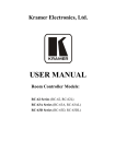
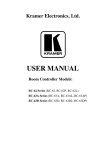
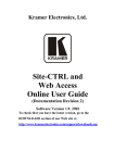
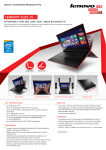
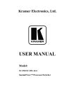
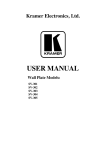
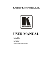
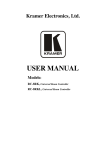
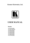
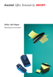
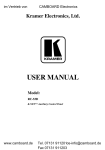
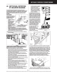
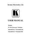
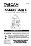
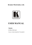
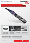
Kramer Electronics, Ltd. USER MANUAL Room Controller Models: RC-62 Series (RC-62, RC-62L) RC-63A Series (RC-63A, RC-63AL) RC-63D Series (RC-63D, RC-63DL) Contents Contents 1 2 3 4 4.1 4.2 4.3 5 5.1 5.2 6 6.1 6.2 6.3 7 Introduction Getting Started Overview Installing the Room Controller Defining the RC-62 and RC-62L Defining the RC-63A and RC-63AL Defining the RC-63D and RC-63DL Using Your Room Controller Operating the Room Controller Using the Macro Buttons Customizing the Controllers' Buttons and Labels Button Labels Inserting the Button Labels Replacing a Button Label Technical Specifications 1 2 2 3 4 6 9 11 15 15 16 16 17 17 18 Figures Figure 1: RC-62 Room Controller Front Panel Figure 2: RC-62 Room Controller Rear Panel Figure 3: RC-63A Room Controller Front Panel (for Europe) Figure 4: RC-63A Room Controller Rear Panel (for Europe) Figure 5: RC-63D Room Controller Front Panel Figure 6: RC-63D Room Controller Rear Panel Figure 7: RC-63D Standalone Power Supply Pinout Figure 8: Example of a Typical RC-63DL Configuration Figure 9: RC-63D connected to the SV-551 SummitView™ Processor / Switcher Figure 10: RC-63DL Labels Setup Figure 11: Sample “Button Labels” Sheet Figure 12: Unscrewing the Faceplate Attachment Screws 4 5 8 8 10 10 12 13 14 15 16 17 Tables Table 1: Defining the Room Controllers' Series Table 2: RC-62 Front Panel Features Table 3: RC-62 Rear Panel Features Table 4: Defining the RC-63A (for the USA) Table 5: RC-63A/EU Front Panel Features (for Europe) Table 6: RC-63A/EU Rear Panel Features Table 7: RC-63D Front Panel Features Table 8: RC-63D Rear Panel Features Table 9: Connection Scheme (for the example in Figure 8) Table 10: The Commands Configuration Table 11: Technical Specifications of the Room Controller Series Table 12: Available RC-6X Models 1 4 5 7 8 9 10 11 13 15 18 19 i Introduction 1 Introduction Welcome to Kramer Electronics! Since 1981, Kramer Electronics has been providing a world of unique, creative, and affordable solutions to the vast range of problems that confront the video, audio, presentation, and broadcasting professional on a daily basis. In recent years, we have redesigned and upgraded most of our line, making the best even better! Our 1,000-plus different models now appear in 11 groups 1 that are clearly defined by function. Congratulations on purchasing your Kramer RC-62 and/or RC-63A and/or RC-63D room controller (defined in Table 1), which are available in European (80mm and 86mm height versions) and American versions. Table 1: Defining the Room Controllers' Series 2 LCD Group-Labels RC-62 Series 3 Printed Group-Labels RC-62L RC-62 RC-63A series With a separate analog volume control adjustment knob RC-63AL RC-63A RC-63D Series With a separate digital volume control adjustment knob RC-63DL RC-63D 4 The Room Controllers are designed to let you control an A/V system with ease— such as our SummitView™ kits 5—in a multimedia classroom or conference room. 1 GROUP 1: Distribution Amplifiers; GROUP 2: Switchers and Matrix Switchers; GROUP 3: Control Systems; GROUP 4: Format/Standards Converters; GROUP 5: Range Extenders and Repeaters; GROUP 6: Specialty AV Products; GROUP 7: Scan Converters and Scalers; GROUP 8: Cables and Connectors; GROUP 9: Room Connectivity; GROUP 10: Accessories and Rack Adapters; GROUP 11: Sierra Products 2 The specific model is not printed on the unit. For example, RC-63DL (with LCD labels) has RC-63D printed on it and can be recognized by the LCD displays on its panel 3 Has LCD labels, letting you program the required group-label 4 The DISPLAY and SOURCES labels are printed on the unit 5 SummitView™ is a complete and simple solution for the integration of media and control in classrooms, training rooms and presentation rooms. SummitView™ is as easy-to-use as it is to specify and install. Everything required, including wall plate interfaces, controllers, amplifiers, speakers, cable and even enclosures ready to be mounted to projection mounts is included. With SummitView™ you get everything you need for a high end integrated media system – just add the displays and sources. All the signals are transmitted over economical CAT 5 cable 1 Getting Started The room controllers—RC-62, RC-63A and RC-63D—can be used as: • System controllers for the SummitView™ system when connected via K-NET 1 cable to the SV-551 or SV-552 SummitView™ Processor / Switcher. When used in this way, no programming of these units is needed and the unit does not require a separate power supply • Advanced, standalone, wall-mounted room controllers. When used in this way, programming of these units is required 2 as well as a separate power supply The package includes the following items: • Any version of the RC-62 series, the RC-63A series or the RC-63D series • 3' (0.91m) USB cable 3 • Screwdriver • This user manual 4 • Configuration software 5 (K-Config or RC-SV) 2 Getting Started This user manual is written for the end user. Refer to the separate Configuration Software Guide (available online) for details of how to install and 6 configure the Room Controller We recommend that you review the contents of this user manual. 3 Overview This user manual describes the RC-62 / RC-63A / RC-63D series. Each of these highly versatile controller interfaces acts as an all-in-one extended remote control panel for control of A/V equipment—especially projectors and associated equipment—in any room (such as classrooms, boardrooms, or auditoriums). They streamline operations and simplify control by integrating audio, video, and computer-video sources into a centralized system. 1 K-NET is a proprietary Kramer protocol for interconnecting Kramer units 2 Refer to the separate online “Configuration Software Guide” at http://www.kramerelectronics.com 3 Part number C-UA/MUB-3 4 Download up-to-date Kramer user manuals from the Internet at this URL: http://www.kramerelectronics.com 5 The relevant configuration software varies according to the firmware version in use. For details, go to our Web site at http://www.kramerelectronics.com 6 That provides information about how to set up the system. This online guide may well be updated on a regular basis. For the latest online guide, go to http://www.kramerelectronics.com 2 KRAMER: SIMPLE CREATIVE TECHNOLOGY Installing the Room Controller Each room controller includes: • Configurable backlit1 buttons to set up any supported2 command • A bidirectional RS-232 wired serial port, for universal display (for example, projectors) and switcher control • Two K-NET ports • Two relays for the simplified and centralized control of room functions (such as lighting, closing blinds, screen settings, and so on) • An IR control port • An IR-learner for the customized control of external sources, receiving the IR commands from different remote transmitters without the need for an external IR remote control unit • Macro mode operation, for programming multiple commands with the press of a single button • Support for firmware upgrade via USB In addition, the RC-63A and the RC-63D feature a separate analog and digital volume adjustment knob, respectively. To achieve the best performance: • Connect only good quality connection cables, thus avoiding interference, deterioration in signal quality due to poor matching, and elevated noise-levels (often associated with low quality cables) • Avoid interference from neighboring electrical appliances and position your Kramer Room Controller away from moisture, excessive sunlight and dust 4 Installing the Room Controller This section defines the: • RC-62, and RC-62L, see Section 4.1 • RC-63A and RC-63AL, see Section 4.2 • RC-63D and RC-63DL, see Section 4.3 1 256 colors are available for backlit buttons (to be configured by the system integrator) 2 To be configured by the system integrator only 3 Installing the Room Controller 4.1 Defining the RC-62 and RC-62L The RC-62 is available as a 1 Gang wall plate (for the USA) or a 2 Gang wall plate (for Europe). It features 6 front panel buttons designed in two groups; one group of 2 buttons, and another group of 4 buttons. Each group can be programmed according to the user's requirements. The: • RC-62 has the DISPLAY and SOURCES labels printed on the unit • RC-62L has an LCD label, letting you program the required group label The RC-62 series includes two relays for the simplified and centralized control of room functions (such as lighting, closing blinds, screen settings, and so on), an IR output, a bidirectional RS-232 port, and two K-NET ports. In addition, the RC-62 features an IR-learner for the customized control of external sources, memorizing the IR commands from different remote transmitters. A USB port is included for programming the RC-62 via a computer. Figure 1, Figure 2, Table 2 and Table 3 define the RC-62, and RC-62L. Version for the USA Version for Europe Figure 1: RC-62 Room Controller Front Panel 1 Table 2: RC-62 Front Panel Features # 1 Feature Function RC-62 - "DISPLAY" and “SOURCE” are printed on the panel “DISPLAY” and “SOURCE” Labels RC-62L - an LCD version on a blue background that displays up to 8 characters at once (programmed via the USB port) 2 DISPLAY Buttons These 2 configurable backlit buttons can set up any supported command 2 3 SOURCE Buttons These 4 configurable backlit buttons can set up any supported command2 1 The USA version shown has LCD Labels (RC-62L), and the European version shown has printed labels (RC-62) 2 By the system integrator only 4 KRAMER: SIMPLE CREATIVE TECHNOLOGY Installing the Room Controller Figure 2: RC-62 Room Controller Rear Panel Table 3: RC-62 Rear Panel Features # Feature Function 1 FIRMWARE UPGRADE For technical support use only Switch 2 Grounding Screw Connect to grounding wire (optional) 3 K-NET TERM Switch For line termination 4 PROGRAM (USB) Connector Connect to a computer for unit configuration 5 IR IN Receiver Receives IR remote commands 6 RELAYS Connections Connect to room items (such as lighting, screen settings, blinds, and so on) 7 IR Connections Control a machine via an IR Emitter 8 RS-232 Connections Connect to the RS-232 connector on the A/V equipment or a PC or other Serial Controller 9 K-NET LOOP Connections On K-NET and K-NET LOOP, PIN GND is for the Ground connection ; PIN B (-) and PIN A (+) are for RS-485, and PIN +12V is for powering the unit 10 K-NET Connections 11 FACTORY RESET Button 1 Press to revert to the default settings, including all the configured buttons 1 The ground connection is sometimes connected to the shield of the RS-485 cable (in most applications, it is not connected) 5 Installing the Room Controller 4.2 Defining the RC-63A and RC-63AL The Kramer RC-63A is available as a 2 Gang wall plate (for Europe and the USA). It features 6 front panel buttons designed in two groups; one group of 2 buttons, and another group of 4 buttons. Each group can be programmed according to the user's requirements. The: • RC-63A has the DISPLAY and SOURCES labels printed on the unit • RC-63AL has LCD labels, letting you program the required group label, as well as rolling text on the display The RC-63A also includes: • An analog volume control adjustment knob • Two relays for the simplified and centralized control of room functions (such as lighting, closing blinds, screen settings, and so on) • An IR output, a bidirectional RS-232 port, and two K-NET ports • An IR-learner for the customized control of external sources, memorizing the IR commands from different remote transmitters A USB port is included for programming the RC-63A via a computer. Table 4 defines the RC-63 and RC-63AL. 6 KRAMER: SIMPLE CREATIVE TECHNOLOGY Installing the Room Controller Table 4: Defining the RC-63A (for the USA) # Feature Function 1 SOURCE Buttons These 4 configurable backlit buttons can set up any supported command 1 2 “DISPLAY” and “SOURCE” Labels RC-63A - "DISPLAY" and “SOURCE” are printed on the panel RC-63AL - an LCD version on a blue background that displays up to 8 characters at once (programmed via the USB port) 3 4 DISPLAY Buttons These 2 configurable backlit buttons can set up any supported command1 VOLUME Knob Rotate clockwise to increase the level # Feature Function 1 GND Connection Ground connection for the potentiometer 2 LEVEL Connection Wiper of potentiometer 3 +V PIN +V connection for the potentiometer 4 Grounding Screw Connect to grounding wire 5 PROGRAM Switch For technical support use only 6 K-NET TERM Switch For line termination 7 PROGRAM (USB) Connector Connect to a computer for unit configuration 8 IR IN Receiver Receives IR remote commands 9 RELAY Connections Connect to room items (such as lighting, screen settings, blinds, and so on) 10 IR Connections Control a machine via an IR Emitter 11 RS-232 Connections Connect to the RS-232 connector on the A/V equipment or a PC or other Serial Controller 12 K-NET LOOP Connections On K-NET and K-NET LOOP, PIN GND is for the Ground connection 2; PIN B (-) and PIN A (+) are for RS-485, and PIN +12V is for powering the unit 13 K-NET Connections 14 FACTORY RESET Button Press to revert to the default settings, including all the configured buttons 1 By the system integrator only 2 The ground connection is sometimes connected to the shield of the RS-485 cable (in most applications, it is not connected) 7 Installing the Room Controller Figure 3 and Table 5 define the RC-63A and the RC-63AL front panels (for Europe): Figure 3: RC-63A Room Controller Front Panel (for Europe) Table 5: RC-63A/EU Front Panel Features (for Europe) # Feature Function 1 DISPLAY Buttons These 2 configurable backlit buttons can set up any supported command 2 “DISPLAY” and “SOURCE” Labels RC-63A - "DISPLAY" and “SOURCE” are printed on the panel RC-63AL - an LCD version on a blue background that displays up to 8 characters at once (programmed via the USB port) 3 SOURCE Buttons These 4 configurable backlit buttons can set up any supported command 4 VOLUME Knob Rotate clockwise to increase the level Figure 4 and Table 6 define the RC-63A Rear panel (for Europe): Figure 4: RC-63A Room Controller Rear Panel (for Europe) 8 KRAMER: SIMPLE CREATIVE TECHNOLOGY Installing the Room Controller Table 6: RC-63A/EU Rear Panel Features # Feature Function 1 GND Connection Ground connection for the potentiometer 2 LVL (LEVEL) Connection Wiper of potentiometer 3 +V PIN +V connection for the potentiometer 4 FIRMWARE UPGRADE Switch For technical support use only 5 IR IN Receiver 6 K-NET TERM Switch For line termination 7 RELAY Connections Connect to room items (such as lighting, screen settings, blinds, and so on) 8 IR Connections Control a machine via an IR Emitter 9 RS-232 Connections Connect to the RS-232 connector on the A/V equipment or a PC or other Serial Controller 10 PROGRAM (USB) Connector Connect to a computer for unit configuration 11 12 K-NET Connections K-NET LOOP Connections On K-NET and K-NET LOOP, PIN GND is for the Ground connection ; PIN B (-) and PIN A (+) are for RS-485, and PIN +12V is for powering the unit 13 Grounding Screw Connect to grounding wire Receives IR remote commands 1 4.3 Defining the RC-63D and RC-63DL The Kramer RC-63D is available as a 2 Gang wall plate for the USA or a 2 Gang wall plate for Europe. It features 6 front panel buttons designed in two groups; one group of 2 buttons, and another group of 4 buttons. Each group can be programmed according to the user's requirements. The: • RC-63D has the DISPLAY and SOURCES labels printed on the unit • RC-63DL is the default room controller included as part of the SummitView™ Standard Kit Box and the SummitView™ Essentials Kit Box and described in that user manual, and has an LCD label, letting you program the required group label, as well as rolling text on the display The RC-63D also includes: • A configurable digital volume control adjustment knob with five LEDs • Two relays for the simplified and centralized control of room functions (such as lighting, closing blinds, screen settings, and so on) • An IR output, a bidirectional RS-232 port, and two K-NET ports • An IR-learner for the customized control of external sources, memorizing the IR commands from different remote transmitters A USB port is included for programming the RC-63D via a computer. Figure 5, Figure 6, Table 7 and Table 8 define the RC-63D and RC-63DL. 1 The ground connection is sometimes connected to the shield of the RS-485 cable (in most applications, it is not connected) 9 Installing the Room Controller Version for the USA Version for Europe Figure 5: RC-63D Room Controller Front Panel Table 7: RC-63D Front Panel Features # Feature Function These 4 configurable backlit buttons can set up any supported command 1 1 SOURCE Buttons 2 RC-63D - "DISPLAY" and “SOURCE” are printed on the panel “DISPLAY” and “SOURCE” Labels RC-63DL - an LCD version on a blue background that displays up to 8 characters at once (programmed via the USB port) 3 DISPLAY Buttons These 2 configurable backlit buttons can set up any supported command1 4 VOLUME LED Lights red, indicating maximum volume 5 VOLUME LEDs Lights green, indicating volume level 6 VOLUME Knob Rotate clockwise to increase the level Figure 6: RC-63D Room Controller Rear Panel 1 By the system integrator only 10 KRAMER: SIMPLE CREATIVE TECHNOLOGY Using Your Room Controller Table 8: RC-63D Rear Panel Features # Feature Function 1 FIRMWARE UPGRADE Switch For technical support use only 2 Grounding Screw Connect to grounding wire 3 K-NET TERM Switch For line termination 4 PROGRAM (USB) Connector Connect to a computer for unit configuration 5 IR IN Receiver Receives IR remote commands 6 RELAY Connections Connect to room items (such as lighting, screen settings, and so on) 7 IR Connections Control a machine via an IR Emitter 8 RS-232 Connections Connect to the RS-232 connector on the A/V equipment or a PC or other Serial Controller 9 K-NET LOOP Connections 10 K-NET Connections On K-NET and K-NET LOOP, PIN GND is for the Ground connection 1; PIN B (-) and PIN A (+) are for RS-485, and PIN +12V is for powering the unit 11 FACTORY RESET Button 5 Using Your Room Controller Press to revert to the default settings, including all the configured buttons This user manual is applicable once the unit is installed and configured 2. The installation process is not detailed in this user manual, and includes: • Configuration via the Windows®-based configuration software and/or the IR learner • Setting up the labels on the buttons, according to your specific requirements 3 • Hardware installation • Connecting the display When the room controller functions as a standalone, wall-mounted room controller, as illustrated in Figure 8: • The controlled machines are connected directly to the room controller • A power supply unit is required • It requires programming 4 The power supply pinout is defined in Figure 7: 1 The ground connection is sometimes connected to the shield of the RS-485 cable (in most applications, it is not connected) 2 By authorized Kramer technical personnel or by an external system integrator 3 It is recommended to place labels on the buttons prior to installing the unit, as this involves removing the face plate 4 Refer to the separate online configuration software technical documentation "K-Config" or RC-SV" at http://www.kramerelectronics.com 11 Using Your Room Controller Figure 7: RC-63D Standalone Power Supply Pinout The room controller is easy to use, as the example in Figure 8 and Table 9 defines 1: 1 Your room controller was installed and configured to suit your specific requirements. This example describes how to setup one of an unlimited number of available setups for the system 12 KRAMER: SIMPLE CREATIVE TECHNOLOGY Using Your Room Controller Figure 8: Example of a Typical RC-63DL Configuration Table 9: Connection Scheme (for the example in Figure 8) This connector: Connects to: REL 1 The screen REL 2 IR OUT and GND PINs A DVD player RS-232 (TX, RX) Terminal Block Connector A projector +12V and GND A power supply unit 1 A PC is connected via the USB connector for setup of the room controller 1 Optional, see Table 11 13 Using Your Room Controller When the room controller is used as a system controller for the SummitView™ system via the proprietary communication channel K-NET, as illustrated in Figure 9: • It requires only a K-NET connection to the SV-551 or SV-552 SummitView™ Processor / Switcher • A power supply unit is not required 1 • No programming of the room controller is needed Figure 9 shows how the room controller is used as part of the SummitView™ system: Figure 9: RC-63D connected to the SV-551 SummitView™ Processor / Switcher 1 Power supplies are sold separately. Consult your Kramer dealer for details 14 KRAMER: SIMPLE CREATIVE TECHNOLOGY Using Your Room Controller 5.1 Operating the Room Controller In the following example 1 that is illustrated in Figure 10, the room controller is labeled with specific functions and each button is programmed 2 to perform several tasks 3 as defined in Table 10. Table 10: The Commands Configuration The Label • • • • OFF • • • • • • DVD • Stop the video player • The projector selects the DVD input • Play the DVD VCR • Stop the DVD • The projector selects the VCR input • Play the VCR VOLUME • Use the VOLUME knob to adjust the audio level ROOM Figure 10: RC-63DL Labels Setup The Macro Sequence ON Power up the projector Power up the DVD player Roll down the projector screen 1 minute delay [for the projector to heat up] • The projector selects the DVD input Power down the projector Stop the DVD player Power down the DVD player Stop the VCR Power down the VCR Roll up the projector screen 5.2 Using the Macro Buttons Pressing any button initiates a macro sequence 4, during which the button blinks (as programmed by the system integrator). 1 This is only one example among numerous possibilities, each button can be configured as required. In this example, two buttons are not assigned 2 By the technical installer 3 A macro sequence, including several commands per button, carried out one after the other 4 The macro sequence can be carried out instantly or can take a while, depending on the delay times included in the sequence 15 Customizing the Controllers' Buttons and Labels 6 Customizing the Controllers' Buttons and Labels This section describes the labels and the buttons. 6.1 Button Labels The backlit buttons 1 are available on plastic caps. We recommend you to insert the labels on the Front Panel buttons before installing the controller, as it involves removing the face plate (see Section 6.2). Figure 11 illustrates the button labels for the macro buttons 2: Figure 11: Sample “Button Labels” Sheet 1 You can program the color of the button with flexible RGB values 2 Installed by the system integrator only 16 KRAMER: SIMPLE CREATIVE TECHNOLOGY Customizing the Controllers' Buttons and Labels 6.2 Inserting the Button Labels To insert a button label, do the following: 1. Unscrew the faceplate attachment screws, using a screwdriver, as Figure 12 illustrates: Figure 12: Unscrewing the Faceplate Attachment Screws 2. Insert the label under the button cap. 3. Place the button cap with the label onto the button base. 6.3 Replacing a Button Label To replace a button label, do the following: 1. Unscrew the faceplate attachment screws, using a screwdriver, as Figure 12 illustrates (see above). 2. Gently remove the transparent button cap with your fingers, or using adhesive tape. 3. Insert the replacement label under the button cap. 4. Replace the button cap with the label onto the button base. 17 Technical Specifications 7 Technical Specifications Table 11 defines the technical specifications: 1 Table 11: Technical Specifications of the Room Controller Series PORTS: OUTPUTS: POWER SOURCE: 1 RS-232 on terminal block connectors; 2 K-NET on terminal block connectors; 1 USB port 2 relays on terminal block connectors (36V AC or DC, 2A, 60VAC maximum on non-inductive load); 1 IR emitter on terminal block connectors RC-62/RC-63A: 12V DC, 100mA RC-62L/RC-63D: 12V DC, 140mA RC-63DL: 12V DC, 200mA FUSE: 500mA, FSMD 2920 ADAPTER: DIMENSIONS: SummitView™ kits: 12V, 5A; independent: 12V/500mA RC-62 (for the USA): 6.9cm x 2.6cm x 11.4cm (2.72" x 1.02" x 4.49", W, D, H) RC-63A and RC-63D: (for the USA): 11.4cm x 2.6cm x 11.4cm (4.49" x 1.02" x 4.49", W, D, H) RC-62, RC-63A and RC-63D (for Europe): 15.2cm x 1.9cm x 8.6cm (5.98" x 0.75" x 3.39", W, D, H) RC-62/EU-80, RC-62L/EU-80, RC-63A/EU-80 and RC-63AL/EU-80 (for Europe): 15.2cm x 1.9cm x 8cm (5.98" x 0.75" x 3.39", W, D, H) 0.14kg. (0.31lbs.) approx. USB cable 3' (0.91m) 2, screwdriver, Kramer configuration software 3 12V DC, 0.5A Power supply 4 Kramer 3.5mm to IR Emitter Control Cable (C-A35/IRE-10), 15 meter and 20 meter IR emitter extension cables WEIGHT: ACCESSORIES: OPTIONS: 1 Specifications are subject to change without notice 2 Part number C-UA/MUB-3 3 "K-Config" or "RC-SV", according to the firmware version in use. For details, go to our Web site at http://www.kramerelectronics.com 4 Model number AD2512C, part number 2535-000251 18 KRAMER: SIMPLE CREATIVE TECHNOLOGY Technical Specifications Table 12 defines the available RC-6X series models 1: Table 12: Available RC-6X Models Model Name Printed Group Labels LCD Group Labels US 1 Gang RC-62 RC-62/JP RC-62/EU-80 RC-62/EU-86 RC-62/GB US 2 Gang Europe 2 Gang (80cm) Europe 2 Gang (86cm) RC-62L RC-62L/JP RC-62L/EU-80 RC-62L/EU-86 RC-62L/GB RC-63A RC-63A/JP RC-63A/EU-80 RC-63A/EU-86 RC-63A/GB RC-63AL RC-63AL/JP RC-63AL/EU-80 RC-63AL/EU-86 RC-63AL/GB RC-63D RC-63D/JP RC-63D/EU-80 RC-63D/EU-86 RC-63D/GB RC-63DL RC-63DL/JP RC-63DL/EU-80 RC-63D2L/EU-86 RC-63DL/GB Supplied Power Supply Worldwide Japan Worldwide Worldwide GB Worldwide Japan Worldwide Worldwide GB Worldwide Japan Worldwide Worldwide GB Worldwide Japan Worldwide Worldwide GB Worldwide Japan Worldwide Worldwide GB Worldwide Japan Worldwide Worldwide GB 1 All models are available in a white front panel finish. For other colors, check with your local Kramer dealer 19 LIMITED WARRANTY Kramer Electronics (hereafter Kramer) warrants this product free from defects in material and workmanship under the following terms. HOW LONG IS THE WARRANTY Labor and parts are warranted for seven years from the date of the first customer purchase. WHO IS PROTECTED? Only the first purchase customer may enforce this warranty. WHAT IS COVERED AND WHAT IS NOT COVERED Except as below, this warranty covers all defects in material or workmanship in this product. The following are not covered by the warranty: 1. Any product which is not distributed by Kramer, or which is not purchased from an authorized Kramer dealer. If you are uncertain as to whether a dealer is authorized, please contact Kramer at one of the agents listed in the Web site www.kramerelectronics.com. 2. Any product, on which the serial number has been defaced, modified or removed, or on which the WARRANTY VOID IF TAMPERED sticker has been torn, reattached, removed or otherwise interfered with. 3. Damage, deterioration or malfunction resulting from: i) Accident, misuse, abuse, neglect, fire, water, lightning or other acts of nature ii) Product modification, or failure to follow instructions supplied with the product iii) Repair or attempted repair by anyone not authorized by Kramer iv) Any shipment of the product (claims must be presented to the carrier) v) Removal or installation of the product vi) Any other cause, which does not relate to a product defect vii) Cartons, equipment enclosures, cables or accessories used in conjunction with the product WHAT WE WILL PAY FOR AND WHAT WE WILL NOT PAY FOR We will pay labor and material expenses for covered items. We will not pay for the following: 1. Removal or installations charges. 2. Costs of initial technical adjustments (set-up), including adjustment of user controls or programming. These costs are the responsibility of the Kramer dealer from whom the product was purchased. 3. Shipping charges. HOW YOU CAN GET WARRANTY SERVICE 1. To obtain service on you product, you must take or ship it prepaid to any authorized Kramer service center. 2. Whenever warranty service is required, the original dated invoice (or a copy) must be presented as proof of warranty coverage, and should be included in any shipment of the product. Please also include in any mailing a contact name, company, address, and a description of the problem(s). 3. For the name of the nearest Kramer authorized service center, consult your authorized dealer. LIMITATION OF IMPLIED WARRANTIES All implied warranties, including warranties of merchantability and fitness for a particular purpose, are limited in duration to the length of this warranty. EXCLUSION OF DAMAGES The liability of Kramer for any effective products is limited to the repair or replacement of the product at our option. Kramer shall not be liable for: 1. Damage to other property caused by defects in this product, damages based upon inconvenience, loss of use of the product, loss of time, commercial loss; or: 2. Any other damages, whether incidental, consequential or otherwise. Some countries may not allow limitations on how long an implied warranty lasts and/or do not allow the exclusion or limitation of incidental or consequential damages, so the above limitations and exclusions may not apply to you. This warranty gives you specific legal rights, and you may also have other rights, which vary from place to place. NOTE: All products returned to Kramer for service must have prior approval. This may be obtained from your dealer. This equipment has been tested to determine compliance with the requirements of: EN-50081: EN-50082: CFR-47: "Electromagnetic compatibility (EMC); generic emission standard. Part 1: Residential, commercial and light industry" "Electromagnetic compatibility (EMC) generic immunity standard. Part 1: Residential, commercial and light industry environment". FCC* Rules and Regulations: Part 15: “Radio frequency devices Subpart B Unintentional radiators” CAUTION! Servicing the machines can only be done by an authorized Kramer technician. Any user who makes changes or modifications to the unit without the expressed approval of the manufacturer will void user authority to operate the equipment. Use the supplied DC power supply to feed power to the machine. Please use recommended interconnection cables to connect the machine to other components. * FCC and CE approved using STP cable (for twisted pair products) 20 KRAMER: SIMPLE CREATIVE TECHNOLOGY For the latest information on our products and a list of Kramer distributors, visit our Web site: www.kramerelectronics.com, where updates to this user manual may be found. We welcome your questions, comments and feedback. Safety Warning: Disconnect the unit from the power supply before opening/servicing. Caution Kramer Electronics, Ltd. Web site: www.kramerelectronics.com E-mail: [email protected] P/N: 2900-000473 REV 2