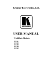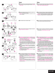
1
Kramer Electronics, Ltd. USER MANUAL Model: SV-552/SV-552 ALC SummitView™ Processor/Switcher Contents Contents 1 2 Introduction Getting Started PART I 3 3.1 3.2 3.3 Overview Basic SummitView™ SV-552 Installation Shielded Twisted Pair and Unshielded Twisted Pair 8-Step SummitView™ Basic System Quick Installation Guide PART II 4 4.1 Your SummitView™ System The SV-552 SummitView™ Processor/Switcher Defining the SV-552 Processor/Switcher DDC Support PART III Detailed Installation Instructions 1 1 2 2 2 3 4 6 6 9 10 5 5.1 5.2 5.3 6 6.1 6.2 7 7.1 Connecting the SV-552 SummitView™ Processor/ Switcher Connecting the SV-552 Processor/Switcher Operating the SV-552 Processor/Switcher Remotely Installing the SV-552 in a 19” Rack (Optional) The RC-63DL Room Controller Defining the RC-63DL Connecting the Room Controller Defining and Connecting the Wall Plates Defining the Wall Plates (U.S.) 10 10 11 12 13 13 15 16 17 7.1.1 7.1.2 7.1.3 7.1.4 Defining the SV-301xl (U.S.) Defining the SV-302 (U.S.) Defining the SV-306 (U.S.) Defining the SV-307 (U.S.) 17 19 20 21 7.2 Defining the Wall Plates (England and Europe) 22 7.2.1 7.2.2 7.2.3 Defining the SV-301xl (England and Europe) Defining the SV-302 (England and Europe) Defining the SV-306 (England and Europe) 22 23 24 7.3 Connecting the Wall Plates to the SV-552 25 7.3.1 7.3.2 7.3.3 Connecting the SV-301xl Wall Plate to the SV-552 Connecting the SV-302 Wall Plate to the SV-552 Connecting the SV-306 Wall Plate to the SV-552 (Optional) 25 26 27 8 8.1 8.2 8.3 9 Wiring the TP LINE IN/LINE OUT Connectors Wiring the Twisted Pair RJ-45 Terminals (U.S.) Wiring the Terminal Block (England and Europe) Cabling for the SV-306 and SV-307 Grounding the Wall Plate 28 28 29 29 30 PART IV Further information 31 i Contents 10 10.1 10.2 11 12 13 14 15 Customizing the Controllers' Buttons and Labels Backlit Buttons Button Label Sheet SummitView™ System Cables SummitView™ Cable Termination Technical Specifications ADA Requirements SV-552 SummitView™ Essentials Basic System Check List 31 31 31 32 33 35 36 38 Figures Figure 1: SV-552 SummitView™ Processor / Switcher Front and Rear Panels Figure 2: SV-552 SummitView™ Processor / Switcher Underside Figure 3: Connecting the SV-552 Figure 4: RC-63DL Room Controller Front Panel Figure 5: RC-63DL Room Controller Rear Panel Figure 6: Connecting the RC-63DL to the SV-552 SummitView™ Processor/Switcher Figure 7: Connecting the SV-301xl to the SV-552 Figure 8: Connecting the SV-302 to the SV-552 Figure 9: Connecting the SV-306/307 to the SV-552 Figure 10: Wiring the K-Net Connector Figure 11: Sample Button Labels Sheet Figure 12: Stickers Affixed to Cables Figure 13: Overhead and Side Clearance Requirements Figure 14: High/Low Forward, Side and Over Obstruction Reach Limit Requirements ii 7 9 11 14 14 16 25 26 27 30 31 34 36 37 KRAMER: SIMPLE CREATIVE TECHNOLOGY Contents Tables Table 1: Quick Installation Guide for the SummitView™ Basic System Table 2: SV-552 SummitView™ Processor/Switcher Underside Features Table 3: SV-552 SummitView™ Processor/Switcher Underside Features Table 4: RC-63DL Room Controller Front Panel Features Table 5: RC-63DL Room Controller Rear Panel Features Table 6: Defining the SV-301xl (U.S.) Table 7: Enclosing a Wall Plate (U.S.) in its Plastic Frame Table 8: Defining the SV-302 (U.S.) Table 9: Defining the SV-306 (U.S.) Table 10: Defining the SV-307 (U.S.) Table 11: Defining the SV-301xl (England and Europe) Table 12: Defining the SV-302 (England and Europe) Table 13: Defining the SV-306 (England and Europe) Table 14: UTP Pinout (U.S.) Table 15: Terminal Block Pinout (England and Europe) Table 16: Grounding Screw, Lock Washers and Ring Tongue Terminal Table 17: Recommended Cables for use with SummitView™ Systems Table 18: SummitView™ Cable Termination Table 19: Technical Specifications of the SV-552 Processor/Switcher Table 20: SV-552 SummitView™ Basic System Check List 4 8 9 14 15 17 18 19 20 21 22 23 24 28 29 30 32 33 35 38 iii Introduction 1 Introduction Welcome to Kramer Electronics! Since 1981, Kramer Electronics has been providing a world of unique, creative, and affordable solutions to the vast range of problems that confront the video, audio, presentation, and broadcasting professional on a daily basis. In recent years, we have redesigned and upgraded most of our line, making the best even better! Our 1,000-plus different models now appear in 11 groups 1 that are clearly defined by function. Congratulations on purchasing your Kramer SummitView™ system! This user manual is comprised of four parts: PART I: A description of the SummitView™ system, its devices and a quick start section PART II: A definition of the SV-552 SummitView™ Processor/Switcher PART III: Detailed installation instructions for installing the wall plates and connecting the SV-552 SummitView™ Processor/Switcher PART IV: Further information 2 Getting Started We recommend that you: • Unpack the equipment carefully and save the original boxes and packaging materials for possible future shipment • Review the contents of this user manual 2 1 GROUP 1: Distribution Amplifiers; GROUP 2: Switchers and Matrix Switchers; GROUP 3: Control Systems; GROUP 4: Format/Standards Converters; GROUP 5: Range Extenders and Repeaters; GROUP 6: Specialty AV Products; GROUP 7: Scan Converters and Scalers; GROUP 8: Cables and Connectors; GROUP 9: Room Connectivity; GROUP 10: Accessories and Rack Adapters; GROUP 11: Sierra Products 2 Download up-to-date Kramer user manuals from http://www kramerelectronics com 1 Overview PART I Your SummitView™ System PART I describes the SummitView™ system and its devices 3 Overview We have designed a complete and simple solution for the integration of media and control in classrooms, training rooms and presentation rooms. SummitView™ is as easy to use as it is to specify and install. The components that make up the SummitView™ system are also available as standalone products. With a SummitView™ kit, you get everything you need for a high end integrated media system – just add the mounting hardware, displays, and sources. All the signals are transmitted over economical TP cable and switched using the SV-552 Switcher/Processor. The SV-552 ALC version is aimed at installers who prefer to design their own SummitView installations. The SV-552 ALC kit differs from the standard SV-552 only in regards to the contents of the box (see Section 15). The SummitView™ System controlled via the network is everything you need from the company you can count on for quality products and the ultimate in customer support – Kramer Electronics. 3.1 Basic SummitView™ SV-552 Installation The usual SummitView™ SV-552 installation includes the following: • SV-552 ALC SummitView™ Processor/Switcher • SV-301xl, SV-302 and SV-306 Wall Plates • RC-63DL Room Controller • SPK-CC444 Speakers • Power adapter (12V DC output) • Required cables (for details see Section 11) • Check list (see Table 20) The following additional products are available for purchase: • SV-301xl, SV-302, SV-306 and SV-307 Wall Plates 1 and compatible cables • Kramer Pico TOOLS™ FC-200 EDID Copier • RC-63D series (RC-63D, RC-63DL), RC-53D series, and RC-63A series (RC-63A, RC-63AL) Room Controllers 2 • A range of ceiling and wall mounted speakers 1 Download the user manual: SV-301/301xl/302/303/304/305/306/307 from http://www kramerelectronics com 2 Download the RC-53D user manual from http://www kramerelectronics com 2 KRAMER: SIMPLE CREATIVE TECHNOLOGY Overview • MT-P9P 9” and MT-P6P 6” center pole sections for the SV-1 Mounting Box which can be attached to any 1.5NFS projector mounting system • SV-1 Pole Mounting Box which can be attached to any 1.5NFS projector mounting system • Additional TP cables (see Section 11) The following items are not provided by Kramer: • Projector (or display device) • Screen (and mounting hardware) • Source devices, such as, DVD/VCR player, scanner, or computer • Installation hardware (where needed), such as, bolts for concrete structural ceilings, toggles (used for screen mounting on dry wall), and so on To achieve the best performance: • Consider the condition of the room—its size, the way it is arranged, whether the walls and ceiling are drywall or cement—that may limit where and how you can install the SummitView™, where required, refer to the ADA requirements (see Section 14). Where an internal installation is impractical (for example, if the walls and ceiling are constructed of cement and you do not want to drill inside them), you can install the SummitView™ system externally, that is, install the SV-552 in a rack (see Section 5.2) using the RK-551 rack mount kit • Connect only good quality connection cables and avoid interference from neighboring electrical appliances and position your SummitView™ away from moisture, and excessive sunlight 3.2 Shielded Twisted Pair and Unshielded Twisted Pair We recommend that you use Shielded Twisted Pair (STP) cable. There are different grades of STP cable available, and we advise you to use the best quality STP cable that you can afford. Our non-skew-free cable, Kramer BC-STP is intended for digital signals and for analog signals where skewing is not an issue. For cases where skewing occurs, our UTP skew-free cable, Kramer BC-XTP, should be used. Bear in mind, though, that we advise using STP cables where possible, since the compliance to electromagnetic interference has been tested using STP cables. Although Unshielded Twisted Pair (UTP) cable might be preferred for long range applications, UTP cable should be installed as far as possible from electric cables, motors, and so on, as these devices tend to create electromagnetic interference. 3 Overview However, since the use of UTP cable might not conform to electromagnetic standards, Kramer does not commit to meeting the standard with UTP cable. 3.3 8-Step SummitView™ Basic System Quick Installation Guide The following guide summarizes how to install a SV-552 SummitView™ basic system (similar principles apply if you are installing other SummitView™ configurations). Table 1: Quick Installation Guide for the SummitView™ Basic System Description 1 Prepare the openings for the wall plates and the room controller. 2 Route the wiring from the proposed location of the SV-552 via: 1 1. STP , BC-DGKat524 or BC-DGKat-623 (SV-306/307) cable to the intended wall plate locations. 2. K-Net cabling to the intended RC-63DL location. 3. Speaker cabling to the intended location of the speakers. 4. If the SV-552 and/or the RC-63DL are to be used as room controllers, route the appropriate control cables to their intended locations. 3 Install the wall plates by connecting the: 1. STP, BC-DGKat524 or BC-DGKat-623 cables to the wall plates and installing the wall plate. 2. BCP-KNET-50 cable to the RC-63DL and installing the RC-63DL (see Section 10). 4 Install the ceiling speakers. 1 There are two types of STP cable recommended with SummitView™: XXP-XXX (plenum-rated for the SummitView™ US) or XXXXX (non-plenum for the SummitView™ Europe) 4 KRAMER: SIMPLE CREATIVE TECHNOLOGY Overview Description 5 Connect the appropriate wiring—STP, BC-DGKat524 or BC-DGKat-623, and BCP-2S-25—from the wall plates and the room controller, and from the SV-552 to the speakers. 6 Install the projector and the screen. Connect the projector to the SV-552 video outputs using the supplied video cables. Connect the RS-232 cable between the SV-552 and the projector. 7 Turn on the SV-552 and the projector. By choosing the input channels on the SV-552 (from the front panel buttons) and on the projector you should be able to switch between inputs connected to the different wall plates. 8 Load the control program on to the SV-552 via its PROGRAM port. For additional information regarding how to program the SV-552, refer to the separate online “K-Config Software Guide” at http://www.kramerelectronics.com. You should now be able to control the SV-552 programmed functions from the RC-63DL. 5 Defining the SV-552 Processor/Switcher PART II The SV-552 SummitView™ Processor/Switcher PART II defines the SV-552 SummitView™ Processor/Switcher 4 Defining the SV-552 Processor/Switcher The Kramer SV-552 SummitView™ Processor/Switcher is designed specifically for the SummitView™ system and is an integral part of it. The SV-552 fits inside the SV-1 housing (optional) and can only be controlled via the default RC-63DL or via one of the other (optional) Kramer K-Net™ compatible controllers. The SV-552 features Twisted Pair video and audio inputs. It also has an IR output for video sources and features a Master controller, as well as a power amplifier and audio line out. The SV-552 front panel controls include six input selector buttons, three LEDs and a USB port. It receives input signals via the RJ-45 connectors from the SV-301xl, SV-302, SV-306 and the SV-307 wall plate devices. The SV-552 RJ-45 TP inputs include: • Two for video • Three for computers • One for HDMI The SV-552 projector outputs include: • VGA output on a 15-pin HD connector • Composite video on an RCA connector • HDMI with embedded audio on a DVI-D connector In addition, the SV-552 features: • Terminal blocks for unbalanced stereo audio speaker output • Terminal blocks for Monitor and Line audio out • Terminal blocks for an AUX input (Line or Mic level) • 10V volume control • Control relays • RS-232 and RS-485 The SV-552 can be controlled by any of the following: • One of Kramer's remote controllers (for example, RC-63DL) via the proprietary communication K-Net channel • Over a network connection via the Ethernet port • Front panel input selector buttons • The RC-4 IR Remote Controller or similar device 6 KRAMER: SIMPLE CREATIVE TECHNOLOGY Defining the SV-552 Processor/Switcher Figure 1 and Table 2 define the front and rear panels of the SV-552 SummitView™ Processor/ Switcher. Figure 1: SV-552 SummitView™ Processor / Switcher Front and Rear Panels 7 Defining the SV-552 Processor/Switcher Table 2: SV-552 SummitView™ Processor/Switcher Underside Features # 1 Feature POWER LED Function Lights when the unit receives power 2 AUTO LED Lights when the unit is configured to automatically identify and select an input according to a preconfigured priority 3 LOCK LED Lights when the front panel buttons are locked 4 VIDEO 1 Press to select the video 1 source VIDEO 2 5 PC 1 PC 2 Press to select the video 2 source INPUTS Buttons (used for testing) Press to select the PC 1 source Press to select the PC 2 source 6 PC 3 HDMI Press to select the PC 3 source Press to select the HDMI source 7 PROGRAM USB Connector Program software - for service use only 8 MONITOR OUT Terminal Block Connect to an external audio amplifier. This is the same as the audio Line Out but lacks level control 9 LINE OUT Terminal Block Connect to an external audio amplifier. This is the same as the Monitor Out but with level control 10 SPKR Terminal Block Connect to the left and right speakers 11 PHANTOM DIP-switch 1 MIC DIP-switch 2 Configures Aux In for use wi h a microphone AUX IN 12 L, G, R Terminal Block Turns on Phantom Power 12V on the Aux In connector Connect to an additional audio source or microphone for mixing with the audio line level input (talk over) 13 IR IN 3.5mm Mini Connector Connect to an IR receiver 14 OUTPUTS TO PROJECTOR DVI Connector Connect to the DVI/HDMI input of he projector 15 PC 1 Connect to the PC 1 source PC 2 INPUTS RJ-45 Connectors PC 3 Connect to the PC 2 source Connect to the PC 3 source 16 ETHERNET RJ-45 Connector Connect to a PC running the Site-CNTL software via he network or Internet for control and configuration of he unit. Default IP set ings: Address 192.168.1.39, port 50000, subnet mask 255.255.255.0 17 K-NET 1 Terminal Block Connect pin G to the Ground connection; Connect pin B and pin A to the RS-485, and pin +12V to the power adapter. For details on connecting K-Net, see Figure 10 18 TERM DIP-switches DIP-switches for line termination of the unit (DIP-switch 1 is for K-Net, DIP-switch 2 is for RS-485) 19 PROJECTOR RS-232 9-pin D-sub Connect to the projector for projector control Connector 20 MUTE Terminal Block Mutes the audio outputs 21 10V VOL Terminal Block Connect to an external poten iometer on a wall plate 2 to adjust the volume of the speakers 22 RELAYS Terminal Block Connect to a room item (such as lighting, screen set ings, blinds, and so on) 23 RS-232 Terminal Block Connect to the RS-232 connector on any serial controlled device 1 K-Net is a proprietary Kramer protocol for interconnecting Kramer units 2 For example, the RC-63DL 8 KRAMER: SIMPLE CREATIVE TECHNOLOGY Defining the SV-552 Processor/Switcher # Feature 24 RS-485 Terminal Block Function Connect to the RS-485 detachable terminal block on a RS-485 controlled device 25 IR OUT Terminal Block Control a machine via an IR Emitter 26 CV RCA Connector Connect to the composite video input of the projector 27 XGA 15-pin HD Connector 28 HDMI/DVI OUTPUTS TO PROJECTOR INPUTS RJ-45 Connectors 29 VIDEO 1 VIDEO 2 30 12V DC Connect to the computer graphics or other display device input of the projector Connect to the HDMI/DVI acceptor 1 Connect to the video 1 source Connect to the video 2 source +12V DC connector for powering the unit Figure 2 and Table 3 define the underside panel of the SV-552 SummitView™ Processor/ Switcher. Figure 2: SV-552 SummitView™ Processor / Switcher Underside Table 3: SV-552 SummitView™ Processor/Switcher Underside Features # Feature 31 SERVICE Switch Function For technical support use only 32 FACTORY RESET Button Press and hold while powering up the unit to reset the audio, switching and Ethernet settings to their factory default values 4.1 DDC Support When establishing a VGA connection between a PC or laptop and a display device, a set of parameters known as EDID which is carried over the DDC channel is exchanged between them. With some PC graphic cards and laptops 1 Using a DVI/HDMI adapter or the Kramer C-HDMI/DVI HDMI to DVI Single Link (18 +1 pin) cable 9 Connecting the SV-552 SummitView™ Processor/ Switcher this information exchange is essential for proper VGA OUT operation. Using the Kramer Pico TOOLS™ FC-200 EDID Copier, you can copy the EDID information from your display and upload it to the SV-301xl wall plate, ensuring trouble-free operation of the system with any PC or Laptop. PART III Detailed Installation Instructions PART III covers connecting the SV-552, installing the Wall Plates and the Room Controller We recommend that after deciding where you want to install the screen and the projector, you install in this order, the: 1. Cables and wires (see Section 5.1). 2. Room controller (see Section 5) and wall plates (see Section 7). 5 Connecting the SV-552 SummitView™ Processor/ Switcher This section describes: • Connecting the SV-552 (see Section 5.1) • Operating the SV-552 Remotely (see Section 5.2) • Installing the SV-552 in a 19” rack (see Section 5.2) 5.1 Connecting the SV-552 Processor/Switcher The example in Figure 3 shows how to connect the SV-552. 10 KRAMER: SIMPLE CREATIVE TECHNOLOGY Connecting the SV-552 SummitView™ Processor/ Switcher Figure 3: Connecting the SV-552 For instructions on wiring the K-Net connector, see Section 8. 5.2 Operating the SV-552 Processor/Switcher Remotely The SV-552 Processor/Switcher can be operated remotely via Ethernet over a LAN using the Kramer Site-CTRL™ software. For details see the Site-CTRL and Web Access Online User Guide 1. 1 Available from http://www kramerelectronics com 11 Connecting the SV-552 SummitView™ Processor/ Switcher 5.3 Installing the SV-552 in a 19” Rack (Optional) This section describes how to mount the SV-552 in a 19” rack using the (optional) RK-551 Rack Adapter. 12 KRAMER: SIMPLE CREATIVE TECHNOLOGY The RC-63DL Room Controller 6 The RC-63DL Room Controller The RC-63DL is a room control panel that can be used independently or as a user interface when connected to a Master Room Controller 1 for control of A/V equipment in any room. RC-63DL is the recommended room controller for an SV-552 SummitView™ basic installation and is described in that user manual. The RC-63DL has an LCD screen, letting you program the required group labels. The Kramer RC-63DL is available as a 2 gang wall plate for either the USA or Europe. It features 6 front panel buttons designed in two groups; one group of 2 buttons, and another group of 4 buttons. Each group is user programmable. The RC-63DL also includes: • A digital volume control adjustment knob with five LEDs • Two relays for the simplified and centralized control of room functions (such as lighting, closing blinds, screen settings, and so on) • An IR output, a bi-directional RS-232 port, and two K-Net ports • An IR-learner for the customized control of external sources, memorizing the IR commands from different remote transmitters A USB port is included for programming the RC-63DL via a computer. 6.1 Defining the RC-63DL Figure 4, Table 4, Figure 5 and Table 5 define the RC-63DL. 1 Such as the Kramer SummitView System or the SL-1 Master Room Controller 13 The RC-63DL Room Controller Figure 4: RC-63DL Room Controller Front Panel Table 4: RC-63DL Room Controller Front Panel Features # 1 Feature SOURCE Buttons Function 4 configurable backlit buttons for any supported command 1 2 “DISPLAY” and LCD on a blue background that displays up to 8 characters at a time (programmed “SOURCE” Labels via the USB port) and includes rolling text 3 DISPLAY Buttons 2 configurable backlit buttons for any supported command 4 VOLUME LED Lights red, indicating maximum volume 5 VOLUME LEDs Lights green, indicating volume level 6 VOLUME Knob Rotate clockwise to increase the level Version for the USA Version for Europe Figure 5: RC-63DL Room Controller Rear Panel 1 By the system integrator only 14 KRAMER: SIMPLE CREATIVE TECHNOLOGY The RC-63DL Room Controller Table 5: RC-63DL Room Controller Rear Panel Features # 1 Feature FIRMWARE UPGRADE Switch Function For technical support use only 2 Grounding Screw Connect to grounding wire 3 K-NET TERM Switch For line termination 4 PROGRAM USB Connector Connect to a computer for unit configuration 5 IR IN Receiver Receives IR remote commands 6 RELAY Connections Connect to room items (such as lighting, screen settings, and so on) 7 8 IR Connections RS-232 Connections Control a machine via an IR Emitter Connect to the RS-232 connector on the A/V equipment or a PC or other Serial Controller 9 K-NET 2 Connections 10 K-NET 1 Connections On K-NET 1 and K-NET 2, PIN GND is for the Ground connection 1; PIN B (-) and PIN A (+) are for RS-485, and PIN +12V is for powering the unit 11 FACTORY RESET Button Press and hold while powering up the unit to reset the audio, switching and Ethernet settings to their factory default values 6.2 Connecting the Room Controller Since the room controller is used as a slave system controller for Master Room Controllers via the proprietary communication channel K-Net (as illustrated in Figure 6): • It requires only a K-Net connection to the Master Room controller • A power supply unit is not required 2 • The room controller can be programmed only via the SV-552 Processor/Switcher Master Room controller 1 The ground connection is sometimes connected to the shield of the RS-485 cable (in most applications, it is not connected) 2 Power supplies are sold separately Consult your Kramer dealer for details 15 Defining and Connecting the Wall Plates Figure 6: Connecting the RC-63DL to the SV-552 SummitView™ Processor/Switcher 7 Defining and Connecting the Wall Plates The SV-301xl and SV-302 Wall Plates are recommended as a part of a SV-552 SummitView™ basic installation. The SV-306 and SV-307 Wall Plates 1 are also available for additional purchase (optional) and require dedicated BC-DGKat524 or BC-DGKat-623 cable. Section 7.1 defines the SV-301xl, SV-302, SV-306 and SV-307 for the United States. Section 7.2 defines the SV-301xl, SV-302 and SV-306 for England and Europe. STP cabling of 50' (15.24m) 2 in length is available which is suitable for the SV-301xl/302 (see Section 11). When required, longer STP cabling can be used but we recommend a maximum transmission range of 30m (100ft). Exceeding the recommended distance may result in reduced image quality. For the TP pinout see Section 8. 1 Download the user manuals for the SV-306 and SV-307 from http://www kramerelectronics com 2 Plenum-rated for the SummitView™ US version; non-plenum for the SummitView™ Europe 16 KRAMER: SIMPLE CREATIVE TECHNOLOGY Defining and Connecting the Wall Plates Advanced User Tip The SV-302 and SV-306 IR OUT port enables remote IR control (this requires the appropriate programming of the SV-552) over the source connected to it (a DVD player, a VHS player, and so on). 7.1 Defining the Wall Plates (U.S.) This section defines the U.S. version of the following wall plates: • SV-301xl (Section 7.1.1) • SV-302 (Section 7.1.2) • SV-306 (Section 7.1.3) • SV-306 (Section 7.1.4) 7.1.1 Defining the SV-301xl (U.S.) The SV-301xl is a single-gang wall plate insert. Table 6 defines the front and rear views of the SV-301xl. Table 6: Defining the SV-301xl (U.S.) SV-301xl Front View # Feature SV-301xl Rear View Function Lights red when receiving power (when no signal is detected); lights green when receiving a signal 1 ON LED 2 COMPUTER IN 15-pin HD Connector Connect to the computer graphics source 3 AUDIO IN 3.5mm Mini Connector Connect to the unbalanced stereo audio source 4 RJ-45 connector Connect to he SV-552 Processor/Switcher 5 DC IN Power Connector Connect to a 12V power supply 17 Defining and Connecting the Wall Plates Table 7 defines the SV-301xl, as an example, in its plastic frame. Table 7: Enclosing a Wall Plate (U.S.) in its Plastic Frame 1 1 Each model that is designed specifically for the U S market can be fitted inside a plastic frame 18 KRAMER: SIMPLE CREATIVE TECHNOLOGY Defining and Connecting the Wall Plates 7.1.2 Defining the SV-302 (U.S.) The SV-302 is a single-gang wall plate insert. Table 8 defines the front and rear views of the SV-302. Table 8: Defining the SV-302 (U.S.) SV-302 Front View SV-302 Rear View # Feature 1 L AUDIO IN RCA Connector Function Connect to the left analog audio source 2 ON LED Lights red when receiving power (when no signal is detected); lights green when receiving a signal 3 R AUDIO IN RCA Connector Connect to the right analog audio source 4 VIDEO IN RCA Connector Connect to the composite video source 5 IR OUT 3.5mm Mini Connector Connect to a machine via an IR Emitter 6 RJ-45 connector Connect to the SV-552 Processor/Switcher 19 Defining and Connecting the Wall Plates 7.1.3 Defining the SV-306 (U.S.) The SV-306 is a single-gang wall plate insert. Table 9 defines the front and rear views of the SV-306. Table 9: Defining the SV-306 (U.S.) SV-306 Front View SV-306 Rear View # Feature 1 ON LED Function Lights red when receiving power (when no signal is detected); lights green when receiving a signal 2 HDMI IN Connector Connect to the HDMI digital source 3 IR OUT 3.5mm Mini Connector Connect to a machine via an IR Emitter 4 RJ-45 connector Connect to the SV-552. Note that the SV-306 requires BC-DGKat524 or BC-DGKat-623 cable for connection (see Section 8.3) U 20 U KRAMER: SIMPLE CREATIVE TECHNOLOGY Defining and Connecting the Wall Plates 7.1.4 Defining the SV-307 (U.S.) The SV307 is a triple-gang wall plate. Table 10 defines the front and rear views of the SV-307. Table 10: Defining the SV-307 (U.S.) SV-307 Front View SV-307 Rear View # 1 Feature DVI IN Connector Function 2 AUDIO IN 3.5mm Mini Connector Connect to the unbalanced stereo audio source 3 ON LED Lights red when receiving power (when no signal is detected); lights green when receiving a signal 4 Ground Connection Ring tongue terminal and grounding screw 5 LINE OUT RJ-45 Connector Connect to the SV-552. Note that the SV-307 requires BC-DGKat524 or BC-DGKat-623 cable for connection (see Section 8.3) Connect to the DVI source U U 21 Defining and Connecting the Wall Plates 1 7.2 Defining the Wall Plates (England and Europe ) This section defines the England and European version of the following wall plates: • SV-301xl (Section 7.2.1) • SV-302 (Section 7.2.2) • SV-306 (Section 7.2.3) 7.2.1 Defining the SV-301xl (England and Europe) The SV-301xl is a single-gang wall plate. The SV-301xl has a terminal block at the rear. Table 11 defines the front and rear views of the SV-301xl. Table 11: Defining the SV-301xl (England and Europe) 2 SV-301xl Rear View 3 SV-301xl Front View # 1 Feature Function ON LED Lights red when receiving power (when no signal is detected); lights green when receiving a signal 2 COMPUTER IN 15-pin HD Connector Connect to the computer graphics source 3 AUDIO IN 3 5mm Mini Connector Connect to the unbalanced stereo audio source 4 Terminal Block Connect to SV-552 using STP cabling (see Section 8.1) 5 GROUND Connection Ring tongue terminal and grounding screw 1 The European versions are equipped with easy terminals, see Section 8 2 2 When mounting in Belgium and Germany, use the standard WP Adapter 3 Some models may have a DC IN connector for connecting to a 12V DC power supply 22 KRAMER: SIMPLE CREATIVE TECHNOLOGY Defining and Connecting the Wall Plates 7.2.2 Defining the SV-302 (England and Europe) The SV-302 is a single-gang wall plate and has a terminal block at the rear. Table 12 defines the front and rear views of the SV-302. Table 12: Defining the SV-302 (England and Europe) 1 SV-302 Front View # Feature SV-302 Rear View Function 1 ON LED Lights red when receiving power (when no signal is detected); lights green when receiving a signal 2 L AUDIO IN RCA Connector Connect to the left analog audio source 3 R AUDIO IN RCA Connector Connect to the right analog audio source 4 VIDEO IN RCA Connector Connect to the composite video source 5 IR OUT 3.5mm Mini Connector Connect to a machine via an IR Emitter 6 Terminal Block Connect to SV-552 using STP cabling (see Section 8.1) 1 When mounting in Belgium and Germany, use the standard WP Adapter 23 Defining and Connecting the Wall Plates 7.2.3 Defining the SV-306 (England and Europe) The SV-306 is a single-gang wall plate and has a terminal block at the rear. Table 13 defines the front and rear views of the SV-306. Table 13: Defining the SV-306 (England and Europe) 1 SV-306 Front View SV-306 Rear View # Feature 1 ON LED Function Lights red when receiving power (when no signal is detected); lights green when receiving a signal 2 3 HDMI IN Connector IR OUT 3.5mm Mini Connector Connect to the HDMI digital source Connect to a machine via an IR Emitter 4 Terminal Block 5 GROUND Connection Connect to SV-552. Note that the SV-306 requires BC-DGKat524 or BC-DGKat-623 cable for connection Ring tongue terminal and grounding screw 6 GND +12V Terminal Block Connect to an optional 12V power supply 1 When mounting in Belgium and Germany, use the standard WP Adapter 24 KRAMER: SIMPLE CREATIVE TECHNOLOGY Defining and Connecting the Wall Plates 7.3 Connecting the Wall Plates to the SV-552 The wall plates are connected to the corresponding inputs on the SV-552 using the supplied 1 STP or optional BC-DGKat524 or BC-DGKat-623 cables (SV-306/307, see Section 8.3). The SV-301xl and the SV-302 U.S. versions have RJ-45 CAT 5 connectors on the rear, as defined in Table 14. The SV-301xl and the SV-302 European versions have terminal blocks on the rear, as defined in Table 11 and Table 12 respectively. The diagrams below show both U.S. and European versions for illustration purposes only. 7.3.1 Connecting the SV-301xl Wall Plate to the SV-552 To connect the SV-301xl as the example in Figure 7 illustrates (see also the separate color illustration in Section 5.1): Figure 7: Connecting the SV-301xl to the SV-552 1. Connect the computer graphics source (for example, a laptop) to the Computer In 15-pin HD connector and to the unbalanced stereo Audio In 3.5mm mini jack on the front of the SV-301xl, for example, using a 1 There are two types of STP cable provided with SummitView™: CP-STP-50 (plenum-rated for the SummitView™ US) or C-STP-50 (non-plenum for the SummitView™ Europe) Other STP cables can also be used However, when using longer STP cables, image quality may be impaired 25 Defining and Connecting the Wall Plates Kramer C-GMA/GMA cable (VGA HD15M +Audio connector to VGA HD15M +Audio connector) 1. 2. On the rear of the SV-301xl, connect the RJ-45 CAT 5 connector using either the RJ-45 connector (U.S. version) or terminal block (European version) to either of the PC 1, PC 2, or PC 3 inputs. 7.3.2 Connecting the SV-302 Wall Plate to the SV-552 To connect the SV-302 as the example in Figure 8 illustrates (see also the separate color illustration in Section 5.1): Figure 8: Connecting the SV-302 to the SV-552 1. On the front of the SV-302, connect the: Composite video source (for example, a DVD player) to the yellow RCA connector, and to the unbalanced stereo audio RCA connectors IR OUT 3.5mm mini connector via an IR Emitter 2 Control cable directly onto the IR sensor window of the controlled device (for example, a DVD player) 1 Not supplied The complete list of Kramer cables is available from http://www kramerelectronics com 2 The Emitter contains a small infrared LED housed in a miniature, mouse shaped, black plastic shell It emits visible red light in addition to IR (infrared) control signals when activated by IR commands sent to it by IR receivers or other controllers The Emitter Control Cable comes with a clear adhesive film included on the emitter housing for attachment to the IR window of the controlled component and pieces of double-sided clear adhesive tape included for replacement purposes 26 KRAMER: SIMPLE CREATIVE TECHNOLOGY Defining and Connecting the Wall Plates 2. On the rear of the SV-302, connect the RJ-45 CAT 5 connector to either input VIDEO 1 or VIDEO 2 input on the SV-552. 7.3.3 Connecting the SV-306 Wall Plate to the SV-552 (Optional) In addition, using BC-DGKat524 or BC-DGKat-623 cable as shown in Figure 9, you can connect the: • SV-306 which accepts an HDMI source and connects to the HDMI input on the rear of the SV-552. The input signals are converted via an RJ-45 CAT 5 connector at the rear, and transmitted to the SV-552. The SV-306 also has an IR out 3.5mm mini connector (connection to the SV-552 is similar to the SV-302) • SV-307 which accepts a DVI component video source on three RCA connectors, as well as a digital audio (S/PDIF) input on an RCA connector, and connects to the HDMI input on the rear of the SV-552. The input signals are converted via an RJ-45 CAT 5 connector at the rear and transmitted to the SV-552. Figure 9: Connecting the SV-306/307 to the SV-552 27 Wiring the TP LINE IN/LINE OUT Connectors 8 Wiring the TP LINE IN/LINE OUT Connectors STP cabling 1 with a length of 15.2m (50ft) in length is available for use with the Kramer A/V SummitView™ systems for connecting to the SV-301xl/302 Wall Plates. When required, longer STP cabling can be used when purchased for standalone wall plates but we recommend a maximum transmission range of 30m (100ft). Exceeding the recommended distance may result in reduced image quality. Connecting the SV-306/307 requires BC-DGKat524 or BC-DGKat-623 cable (see Section 8.3). This section describes how to connect the rear panel for the: • US wall plate versions (see Section 8.1) • European wall plate versions (see Section 8.2) 8.1 Wiring the Twisted Pair RJ-45 Terminals (U.S.) The U.S. versions of the wall plates are equipped with RJ-45 terminals. Table 14 defines the TP pinout, using a straight pin to pin cable with RJ-45 connectors. When using STP cable, connect/solder the cable shield to the RJ-45 connector shield. Table 14: UTP Pinout (U.S.) Wire Color Orange/White 2 Orange 3 Green/White 4 Blue 5 Blue/White 6 Green 7 Brown/White 8 Brown Pair 1 Pair 2 4 and 5 1 and 2 Pair 3 3 and 6 Pair 4 7 and 8 Shield EIA /TIA 568B PIN 1 1 2 34 56 78 1 2 4 5 78 36 1 Plenum-rated for the SummitView™ US version; non-plenum for the SummitView™ Europe 28 KRAMER: SIMPLE CREATIVE TECHNOLOGY Wiring the TP LINE IN/LINE OUT Connectors 8.2 Wiring the Terminal Block (England and Europe) The European versions of the wall plates are equipped with an easy plug-in terminal block for the STP cables. Use the color coded sticker on these terminals for proper connection of the STP cable. Table 15 defines the pinout for the terminal block. Table 15: Terminal Block Pinout (England and Europe) Notes: • Use the connector clips when removing the wires, not when inserting them • Each wire protrudes 9mm in length from the plastic insulation so that it can be easily connected. To prevent the wires crossing, be sure that each wire is completely inserted • With STP cable, the GND pin is used for shielding. Shielding is not needed, but if desired, connect the GND pin of the PC 8.3 Cabling for the SV-306 and SV-307 Kramer engineers have developed special twisted pair cables to best match our digital twisted pair products; the Kramer BCP-DGKat524 (CAT 5 24 AWG), and the Kramer BCP-DGKat623 (CAT 6 23 AWG cable). These specially built cables significantly outperform regular CAT 5/CAT 6 cables. A system range of up to 90m (295ft) at 1080i/SXGA, or up to 30m (98ft) at 1080p/UXGA on shielded BCP-DGKat524 cable; 90m (295ft) at 1080i, or up to 70m (230ft) at 1080p/UXGA on shielded BCP-DGKat623 cable. Note that the STP cable Ground shield must be connected/soldered to the connector shield. 29 Grounding the Wall Plate 9 Grounding the Wall Plate The grounding screw is used to earth the chassis of the unit to the ground of the building, thus preventing static electricity from interfering with the product’s performance. Table 15 defines the grounding screw components. Table 16: Grounding Screw, Lock Washers and Ring Tongue Terminal # Item 1 M3X6 screw 2 1/8" Toothed Lock Washer 3 M3 Ring Tongue Terminal To ground a wall plate: 1. Connect the Ring Tongue terminal to the building grounding point wire (it is recommended to use a green-yellow AWG#18 wire, crimped with a proper hand-tool). 2. Insert the M3x6 screw through the toothed lock washers and the tongue terminal in the order shown above. 3. Insert the M3x6 screw (with the two toothed lock washers and ring tongue terminal) into the grounding screw hole and tighten the screw. Wiring the K-Net™ Connector: Figure 10: Wiring the K-Net Connector 30 KRAMER: SIMPLE CREATIVE TECHNOLOGY Customizing the Controllers' Buttons and Labels PART IV Further information PART IV includes further information 10 Customizing the Controllers' Buttons and Labels This section describes the backlit buttons and the button labels sheet. 10.1 Backlit Buttons The RC-63DL backlit buttons 1 have plastic caps. To insert a label on a button—we recommend doing this before installing the controller, as it involves removing the front plate—unscrew the front plate attachment screws using a screwdriver, gently remove the transparent button cap with your fingers, and insert the label under the button cap. Replace the button cap with the label onto the button base. 10.2 Button Label Sheet Figure 11 illustrates the sample Button Label sheet. Figure 11: Sample Button Labels Sheet 1 You can program the color of the button with flexible RGB values 31 SummitView™ System Cables 11 SummitView™ System Cables Table 17 defines the recommended cables for a SummitView™ installation. Table 17: Recommended Cables for use with SummitView™ Systems Item Description Cable for use with the SV-301xl CP-STP-50/C-STP-50 1 2 STP cable 15.2m (50ft) from SV-301 to SV-552 (1 cable ) Supplied with the SV552 ALC - Cable for use with the SV-302 CP-STP-50/C-STP-50 (1 cable1)2 STP cable 15.2m (50ft) from SV-302 to SV-552 Cables for use with the SV-552 P.S 12V/5A DESKTOP with DC plug (1 cable) POWER CORD 110V (1 cable) Molded Micro VGA to VGA cable 0.91m (3ft), C-MGM/MGM-3 (1 cable) 3 from SV-552 to the display device Molded RCA RG-59 video cable 0.91m (3ft), C-RVM/RVM-3 (1 cable)3 from SV-552 to the display device HDMI to DVI cable 0,91m (3ft), from the SV-552 C-HM/DM-3 to the display device RS-232 cable 0.91m (3ft), from the SV-552 to C-D9M/D9F-3 (1 cable) the display device C-D9M/D9F-3 RS-232 Gender changer Speaker cables, from the SV-552 to the BCP-2S-25 (2 cables) speakers USBA to Mini USB cable 0.91m (3ft), for configuring the SV-552 or the RC-63DL C-UA/MUB-3 (1 cable) 1 1 1 28F Cable for use with the RC-63DL or other controller Balanced Stereo Audio/Control cable 15.2m BCP-KNET-50 (1 cable) (50ft), from the RC-63DL to the SV-552 1 1 1 1 1 1 1 There are two types of STP cable provided with SummitView™: CP-STP-50 (plenum-rated for the SummitView™ U.S.) or C-STP-50 (non-plenum for the SummitView™ Europe) 2 Connect the wall plate to the SV-552 3 Connects the SV-552 to the projector 32 KRAMER: SIMPLE CREATIVE TECHNOLOGY SummitView™ Cable Termination 12 SummitView™ Cable Termination Table 18 defines the SummitView™ cable termination (connector-to-cable). Table 18: SummitView™ Cable Termination C-D9M/D9F-3 RS-232 Cable PINOUT BCP-KNET-50 Cable Pinout (see also Figure 10) BCP-2S-25 Cable Figure 12 defines the stickers affixed to the SummitView™ cables. 33 SummitView™ Cable Termination Figure 12: Stickers Affixed to Cables 34 KRAMER: SIMPLE CREATIVE TECHNOLOGY Technical Specifications 13 Technical Specifications Technical specifications of the SV-552 SummitView™ Processor/Switcher are shown in Table 19. 1 Table 19: Technical Specifications of the SV-552 Processor/Switcher Item Description 1 AUX stereo on a 3-PIN terminal block; 1 HDMI, 3 PC (XGA and Y, Pb, Pr), 1 Composite Video on RJ-45 connectors OUTPUTS: 1 SPKR (speaker) stereo on a 4-PIN terminal block; 1 Projector (XGA) on a 15-pin HD computer graphics video connector; 1 composite video on RCA connector; 1 DVI, 3 DDC (bi-directional, inputs/outputs, as required) on RJ45 connectors 10V Volume, 2 relays on terminal block connectors (36VAC or DC, 2A, 60VAC maximum on non-inductive load), RS-232, and RS-485 3-PIN terminal blocks; IR OUT 2-PIN terminal block MAX. OUTPUT LEVEL: VIDEO: CV 2.6Vpp; XGA 2.2Vpp AUDIO: 7W per channel into 4Ω LINEOUT: 5.8Vpp @max volume, tone controls zeroed BANDWIDTH (-3dB): VIDEO: CV 68MHz; XGA and Y, AUDIO: 20Hz to 20kHz Pb, Pr 130MHz DIFF. GAIN: 0.35% DIFF. PHASE: 0.01Deg. K-FACTOR: <0.05% S/N RATIO: VIDEO: 59dB unweighted, AUDIO: 55dB @1KHz, 66dB @5MHz weighted LINEOUT: 85dB @1KHz CONTROLS: IR, RS-232, RS-485, Ethernet, K-Net COUPLING: VIDEO: DC AUDIO/LINEOUT: Input: AC; Output: DC AUDIO THD + NOISE: AUDIO: 1.1% @1KHz, 12.8Vpp, LINEOUT: 0.063% @1KHz 2.4Vpp AUDIO 2nd HARMONIC: AUDIO: 0.4% @1KHz, 8Vpp, LINEOUT: 0.02% @1KHZ, 2.4Vpp AUDIO INPUT SENSITIVITY: 140mVpp AUDIO VOLTAGE GAIN: 97 x 39.7dB POWER SOURCE: 12V 4.3A DIMENSIONS: 27.78cm x 7.65cm x 4.36cm (10.94" x 3.01" 1.72") W, D, H WEIGHT: 0.65kg (1.43lbs) approx. ACCESSORIES: See Table 17 OPTIONS: Power supply, a pair of detachable rack ears and shelf, RC-4 Infrared Remote Controller, RK-551 (for installing in a 19” rack) INPUTS: 1 Specifications are subject to change without notice 35 ADA Requirements 14 ADA Requirements When not mounting the SV-552 in a rack, attention must be paid to overhead clearances. Refer to the ADA Standards for Accessible Design (courtesy of 1 the U.S. Department of Justice) , and in particular, section 4-4", "Head Room": 30F Figure 13: Overhead and Side Clearance Requirements 1 You can download the file from their Web site at http://www.ada.gov/stdspdf.htm 36 KRAMER: SIMPLE CREATIVE TECHNOLOGY ADA Requirements Figure 14: High/Low Forward, Side and Over Obstruction Reach Limit Requirements 37 SV-552 SummitView™ Essentials Basic System Check List 15 SV-552 SummitView™ Essentials Basic System Check List Remove this list from the user manual and use it to check that all components are present. Table 20: SV-552 SummitView™ Basic System Check List PART DESCRIPTION # SV-552 SummitView™ Processor/Switcher 1 C-D9M/D9F-3 RS-232 cable 0.91 (3ft) 1 BCP-2S-25 Speaker cable 2 BCP-KNET-50 Balanced Audio/Control cable 15.2m (50ft) 1 C-UA/MUB-3 USB A to mini USB B cable 0.91m (3ft) 1 P.S 12V/5A US and EU models 1 POWER CORD According to country 1 CD-ROM K-Config Configuration software 1 SCREWDRIVER For installation 1 RC-63DL Room Controller 1 C-UA/MUB-3 USB A to mini USB B cable 0.91m (3ft) 1 CD-ROM RC Configuration software 1 Wall Plate (Computer Graphics Video + Audio) 1 STP cable 15.2m (50ft) 1 SV-301xl C(P)-STP-50 1 C-MGM/MGM-3 Molded Micro VGA to VGA cable 0.91m (3ft) 1 Wall Plate (Composite Video + Audio) 1 C(P)-STP-50 STP cable 15.2m (50ft) 1 C-RVM/RVM-3 Molded RCA RG-59 video cable 0.91m (3ft) 1 SV-302 1 1 CP-STP-50 is plenum-rated for the SummitView™ U S ; C-STP-50 is non-plenum for the SummitView™ Europe 38 KRAMER: SIMPLE CREATIVE TECHNOLOGY LIMITED WARRANTY Kramer Electronics (hereafter Kramer) warrants this product free from defects in material and workmanship under the following terms HOW LONG IS THE WARRANTY Labor and parts are warranted for three years from the date of the first customer purchase WHO IS PROTECTED? Only the first purchase customer may enforce this warranty WHAT IS COVERED AND WHAT IS NOT COVERED Except as below, this warranty covers all defects in material or workmanship in this product The following are not covered by the warranty: 1 Any product which is not distributed by Kramer, or which is not purchased from an authorized Kramer dealer If you are uncertain as to whether a dealer is authorized, please contact Kramer at one of the agents listed in the Web site www kramerelectronics com 2 Any product, on which the serial number has been defaced, modified or removed, or on which the WARRANTY VOID IF TAMPERED sticker has been torn, reattached, removed or otherwise interfered with 3 Damage, deterioration or malfunction resulting from: i) Accident, misuse, abuse, neglect, fire, water, lightning or other acts of nature ii) Product modification, or failure to follow instructions supplied with the product iii) Repair or attempted repair by anyone not authorized by Kramer iv) Any shipment of the product (claims must be presented to the carrier) v) Removal or installation of the product vi) Any other cause, which does not relate to a product defect vii) Cartons, equipment enclosures, cables or accessories used in conjunction with the product WHAT WE WILL PAY FOR AND WHAT WE WILL NOT PAY FOR We will pay labor and material expenses for covered items We will not pay for the following: 1 Removal or installations charges 2 Costs of initial technical adjustments (set-up), including adjustment of user controls or programming These costs are the responsibility of the Kramer dealer from whom the product was purchased 3 Shipping charges HOW YOU CAN GET WARRANTY SERVICE 1 2 3 To obtain service on you product, you must take or ship it prepaid to any authorized Kramer service center Whenever warranty service is required, the original dated invoice (or a copy) must be presented as proof of warranty coverage, and should be included in any shipment of the product Please also include in any mailing a contact name, company, address, and a description of the problem(s) For the name of the nearest Kramer authorized service center, consult your authorized dealer LIMITATION OF IMPLIED WARRANTIES All implied warranties, including warranties of merchantability and fitness for a particular purpose, are limited in duration to the length of this warranty EXCLUSION OF DAMAGES The liability of Kramer for any effective products is limited to the repair or replacement of the product at our option Kramer shall not be liable for: 1 Damage to other property caused by defects in this product, damages based upon inconvenience, loss of use of the product, loss of time, commercial loss; or: 2 Any other damages, whether incidental, consequential or otherwise Some countries may not allow limitations on how long an implied warranty lasts and/or do not allow the exclusion or limitation of incidental or consequential damages, so the above limitations and exclusions may not apply to you This warranty gives you specific legal rights, and you may also have other rights, which vary from place to place NOTE: All products returned to Kramer for service must have prior approval This may be obtained from your dealer This equipment has been tested to determine compliance with the requirements of: EN-50081: EN-50082: CFR-47: "Electromagnetic compatibility (EMC); generic emission standard Part 1: Residential, commercial and light industry" "Electromagnetic compatibility (EMC) generic immunity standard Part 1: Residential, commercial and light industry environment" FCC* Rules and Regulations: Part 15: “Radio frequency devices Subpart B Unintentional radiators” CAUTION! Servicing the machines can only be done by an authorized Kramer technician Any user who makes changes or modifications to the unit without the expressed approval of the manufacturer will void user authority to operate the equipment Use the supplied DC power supply to feed power to the machine Please use recommended interconnection cables to connect the machine to other components * FCC and CE approved using STP cable (for twisted pair products) 39 For the latest information on our products and a list of Kramer distributors, visit our Web site www.kramerelectronics.com where updates to this user manual may be found. We welcome your questions, comments and feedback. Safety Warning: Disconnect the unit from the power supply before opening/servicing. Caution Kramer Electronics, Ltd. Web site: www.kramerelectronics.com E-mail: [email protected] P/N: 2900-000603 REV 2