1
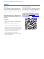
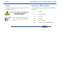
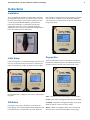
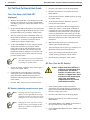
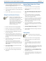
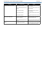
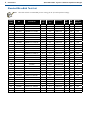
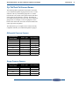
Quick Start Guide
Cyl-Tel® & Tank-Tel®
Liquid Level Gauges
Designed and Built by:
Chart Inc.
407 7th Street NW
New Prague, MN 56071 USA
(800) 400-4683
Part Number 20664277 Rev. D
© 2015 Chart Inc.
iii
Quick Start Guide - Cyl-Tel® & Tank-Tel® Liquid Level Gauges
Contents
Revision Log . . . . . . . . . . . . . . . . . . . . . . . . . . . . . . . . . . . . . . . . . . . . . . .iv
Preface . . . . . . . . . . . . . . . . . . . . . . . . . . . . . . . . . . . . . . . . . . . . . . . . . . . .
General . . . . . . . . . . . . . . . . . . . . . . . . . . . . . . . . . . . . . . . . . . . . . . . . . .
Highlights . . . . . . . . . . . . . . . . . . . . . . . . . . . . . . . . . . . . . . . . . . . . . . . . .
Quick Start Guide . . . . . . . . . . . . . . . . . . . . . . . . . . . . . . . . . . . . . . . . . . . . .
Terms . . . . . . . . . . . . . . . . . . . . . . . . . . . . . . . . . . . . . . . . . . . . . . . . . . .
Acronyms / Abbreviations . . . . . . . . . . . . . . . . . . . . . . . . . . . . . . . . . . . . . . . .
1
1
1
1
2
2
Instructions . . . . . . . . . . . . . . . . . . . . . . . . . . . . . . . . . . . . . . . . . . . . . . . . . . 3
Installation . . . . . . . . . . . . . . . . . . . . . . . . . . . . . . . . . . . . . . . . . . . . . . . . 3
Initial Setup . . . . . . . . . . . . . . . . . . . . . . . . . . . . . . . . . . . . . . . . . . . . . . . . 3
ON Button . . . . . . . . . . . . . . . . . . . . . . . . . . . . . . . . . . . . . . . . . . . . . . . . 3
Keypad Use . . . . . . . . . . . . . . . . . . . . . . . . . . . . . . . . . . . . . . . . . . . . . . . . 3
Cyl-Tel/Tank-Tel Quick Start Guide . . . . . . . . . . . . . . . . . . . . . . . . . . . . . . . . . . . 4
First Time Setup (‘NO TANK SET’ displayed) . . . . . . . . . . . . . . . . . . . . . . . . . . . 4
DP Sensor (selecting correct sensor type) . . . . . . . . . . . . . . . . . . . . . . . . . . . . . . 4
DP Zero (Tare the DP Sensor) . . . . . . . . . . . . . . . . . . . . . . . . . . . . . . . . . . . . 4
Setting Correct Saturation Pressure . . . . . . . . . . . . . . . . . . . . . . . . . . . . . . . . . 5
Standard Tank Configuration (If Gauge Previously Setup) . . . . . . . . . . . . . . . . . . . . . 5
Setting Alarms . . . . . . . . . . . . . . . . . . . . . . . . . . . . . . . . . . . . . . . . . . . . 5
Troubleshooting . . . . . . . . . . . . . . . . . . . . . . . . . . . . . . . . . . . . . . . . . . . . . . 6
Standard MicroBulk Tank List . . . . . . . . . . . . . . . . . . . . . . . . . . . . . . . . . . . . . . 8
Cyl-Tel/Tank-Tel Sensor Names . . . . . . . . . . . . . . . . . . . . . . . . . . . . . . . . . . . . . 9
Differential Pressure Sensors . . . . . . . . . . . . . . . . . . . . . . . . . . . . . . . . . . . . 9
Gauge Pressure Sensors . . . . . . . . . . . . . . . . . . . . . . . . . . . . . . . . . . . . . . . 9
iv Table of Contents
Quick Start Guide - Cyl-Tel® & Tank-Tel® Liquid Level Gauges
Revision Log
Revision Level
Date
B
07/15/2014
Description
Reformat with new layout and update to include Gen 4.
C
10/06/2014
Add Sensor Names section
D
04/10/2015
Update information in #5 of DP Sensor (Selecting correct sensor type) section
Quick Start Guide - Cyl-Tel® & Tank-Tel® Liquid Level Gauges
Preface
General
Quick Start Guide
The Cyl-Tel & Tank-Tel Liquid Level Gauges are digital
electronic level gauges. The gauge has been updated to Gen
4 to include the latest in electronic and differential pressure
measurement technologies. The new design includes accurate
liquid level reading using differential pressure, a graphical
display, and a simplified logic with nine selectable units
of measure that eliminate the need for lookup charts. The
Cyl-Tel & Tank-Tel gauges are telemetry-ready with built-in
outputs which eliminate the need for additional boards and
is completely compatible to most current telemetry system
requirements.
This Cyl-Tel & Tank-Tel Quick Start Guide is designed to be
used in conjunction with PN 20544482 Cyl-Tel & Tank-Tel
Product Manual. If there are any questions regarding the
operation of the Cyl-Tel/Tank-Tel gauge, contact Chart’s
Technical Service at 1-800-400-4683.
Highlights
• Improves customer readability by eliminating calibration
charts
• Programmable to tank model or by tank geometry
• Telemetry-ready outputs compatible with many systems
• Standard pulse and voltage outputs (and optional 4-20mA
with interface board); as well as 3 alarm (digital) outputs
• Power: Battery (2 x 1.5V Long Life Lithium) powered or
optional 12Vdc adapter (for continuous power)
• Improved readability with a graphical display
• Built-in additional analog input port (0-5V) for optional
pressure sensor connection
To obtain a complete installation and user manual, please
scan QR code or go to: www.chartparts.com and click on
Manuals, then MicroBulk, then PN 20544482 Cyl-Tel &
Tank-Tel Product Manual.
1
2
Preface
Quick Start Guide - Cyl-Tel® & Tank-Tel® Liquid Level Gauges
Terms
Acronyms / Abbreviations
Throughout this quick start guide safety precautions will be
designated as follows:
The following acronyms / abbreviations are used throughout
this manual:
Caution! Description of a condition that
can result in equipment or
component damage.
Note: A statement that contains information
that is important enough to emphasize or
repeat.
Ar
Argon
CO2
Carbon Dioxide
N2
Nitrogen
O2
Oxygen
PB
Pressure Builder
PSID
Pounds per Square Inch Differential
Quick Start Guide - Cyl-Tel® & Tank-Tel® Liquid Level Gauges
Instructions
Installation
The Cyl-Tel/Tank-Tel Liquid Level Gauge has a maximum
operating differential pressure of 29 psid. In order to protect
the sensor from damage, ensure that the equalization valve
is in the ‘EQUALIZATION SERVICE’ position before
removing or installing a Cyl-Tel/Tank-Tel Gauge onto
a Chart tank. If the valve is not in equalization then the
diaphragm in the sensor can be permanently damaged. Refer
to the user manual for more information.
Initial Setup
Upon receiving, the Cyl-Tel/Tank-Tel Gauge will look one of
two ways. If it has been setup at the factory it will show 0%
(left). If it has not been setup it will show a sad face (right).
If “NO TANK SET” is displayed, refer to First Time Setup in
this guide.
tank’s liquid level and pressure (pressure display is optional).
Once the unit is on and the level is displayed, holding the
‘ON’ button for 15 seconds will access the Cyl-Tel/Tank-Tel
Gauge setup menus.
Keypad Use
There are four buttons on the Cyl-Tel/Tank-Tel Gauge face.
Each one has a different purpose. Each button performs the
operation of the text box above the button on the screen.
FILL - This button will lock the display on for 15 minutes.
UNITS - This button will toggle the different units available.
ON Button
Pressing the ‘ON’ button will turn the Cyl-Tel/Tank-Tel
Gauge display on and run through the startup diagnostics and
tests. When the test is complete the screen will display the
ALARMS - This button will toggle the display of any setup
alarms on and off. It will not clear any alarms.
MENU - When on, holding this button for 15 seconds will
allow the user to enter the ‘MAIN MENU’ for the gauge.
3
4
Instructions
Quick Start Guide - Cyl-Tel® & Tank-Tel® Liquid Level Gauges
Cyl-Tel/Tank-Tel Quick Start Guide
First Time Setup (‘NO TANK SET’
displayed)
1.
With the ‘NO TANK SET’ screen displayed, press and
hold the ‘ON’ button for 15 seconds (‘PLEASE WAIT’
will display) or until the ‘SETUP STD TANK’ screen is
displayed.
2.
On the ‘SETUP STD TANK’ menu use the up and down
buttons to toggle through the different tank types. Select
the desired tank type by pressing the ‘NEXT’ button.
3.
The next screen is the ‘SET CONTENTS’ menu. Use
the up and down buttons to cycle through the different
contents (N2, O2, Ar, and CO2). Select the desired
contents by pressing the ‘NEXT’ button.
4. On the ‘SETUP DISPLAY’ screen, select the desired
default units-of-measure by pressing the ‘NEXT’
button. Then use the up and down buttons to scroll
through the various units. This selection will be the
default units which are displayed every time the ‘ON’
button is pressed. Once the desired units are selected,
press the ‘NEXT’ button.
Note: Level reading can always be displayed in
other units-of-measure on the main screen
by pressing the ‘UNITS’ button.
1.
Press the ‘ON’ button to turn on the gauge display.
2.
Hold the ‘ON’ button for 15 seconds to access the
MAIN MENU.
3.
Scroll down and select the ‘MORE’ option by pressing
the ‘NEXT’ button.
4.
Scroll down and select the ‘DP Sensor’ option by
pressing the ‘NEXT’ button.
5.
Use the up or down arrow buttons to toggle between
sensor types. If there is a brass block on the back of
your gauge the sensor type should be DP4. If there is
a stainless steel sensor on the back of your gauge the
sensor type should be DP1. The sensor type is on the
label on the top or back of the Cyl-Tel/Tank-Tel gauge.
Refer to the sensor names table in this guide for more
information.
6.
When the desired sensor type is selected press the
‘NEXT’ button to apply the setting.
7.
After selecting the correct sensor type remember to set
the DP Zero setting in the following section.
8.
To save these settings scroll down and select the
‘SAVE’ option by pressing the ‘NEXT’ button.
9.
Exit the menu by pressing the ‘EXIT’ button.
DP Zero (Tare the DP Sensor)
5. To save the settings scroll down to the ‘SAVE’ option
and press the ‘NEXT’ button.
Caution! Proper calibration (DP Zero) is
critical for accurate liquid level
measurement. The DP Zero
function is similar to the “Tare”
function on a digital scale. Both
functions set the measurement
range ‘zero’ point which
compensates for any intrinsic
offset within the sensor.
6. Confirm that the correct DP Sensor is selected by
following the steps in the DP Sensor section in this
guide. Remember to DP Zero the gauge after it is
installed by following the steps in the DP Zero section
in this manual.
7. Press the ‘EXIT’ button to return to the main screen.
1.
If tank contains product (liquid), then turn the
equalization valve located near the Cyl-Tel/Tank-Tel
gauge to the EQUALIZATION/SERVICE position. If
the tank is empty, skip to step 2.
2.
Press the ‘ON’ button to turn on the gauge display.
3.
Hold the ‘ON’ button for 15 seconds to access the
MAIN MENU.
4.
In the MAIN MENU select ‘MORE’, at the bottom of
the screen and press the ‘NEXT’ button.
5.
On the MORE FEATURES menu select ‘DP Zero’ and
press ‘NEXT.’
DP Sensor (selecting correct sensor type)
Note: The gauge can come with a variety of
different sensors depending on the range
needed for the tank. To ensure an accurate
reading the correct sensor must be chosen.
Note: Changing the sensor type also resets the
DP Zero setting. Upon changing the DP
Sensor type remember to follow the DP
Zero procedure.
Quick Start Guide - Cyl-Tel® & Tank-Tel® Liquid Level Gauges
6.
The screen will display “PLEASE WAIT” for a few
seconds at the bottom of the screen and then the new DP
Zero value will appear below the old.
7.
Apply the new DP Zero by pressing the ‘NEXT’ button.
8.
To save the settings scroll down to ‘SAVE’ and press the
‘NEXT’ button.
9.
Press the ‘EXIT’ button to return to the main screen.
Setting Correct Saturation Pressure
Note: Setting the correct liquid saturation
pressure is also critical for accurate liquid
level measurement. The set pressure is
used to determine the liquid density, which
in turn is used in the liquid level and
volume calculations. An incorrect pressure
setting can cause the level reading to be
significantly higher or lower than the
actual level within the tank.
1.
Press the ‘ON’ button to turn on the gauge display.
2.
Hold the ‘ON’ button to access the MAIN MENU.
3.
Select ‘SET CUSTOM’ and press the ‘NEXT’ button.
4.
Scroll down and select the ‘PRESSURE’ option and
press the ‘NEXT’ button.
5.
Using the up and down buttons, set the pressure to an
average between Orca/delivery truck pressure and PB
set point of the tank. Press the ‘NEXT’ button to apply
the setting.
6.
Scroll down and select ‘SAVE.’ Press the ‘NEXT’
button to save the setting.
Instructions
Standard Tank Configuration (If Gauge
Previously Setup)
1.
Press the ‘ON’ button to turn on the gauge display.
2.
Hold the ‘ON’ button for 15 seconds to access the
MAIN MENU.
3.
Select ‘SET TANK’ and press the ‘NEXT’ button. This
allows access to the standard tank list built into the
gauge.
4.
Use the up and down buttons to cycle through the
different tanks. Select the desired tank and press the
‘NEXT’ button to apply the setting.
5.
On the ‘SET CONTENTS’ screen use the up and down
buttons to set the correct liquid contents of the tank.
With the desired contents selected press the ‘NEXT’
button to apply the setting.
6.
On the ‘SETUP DISPLAY’ screen select the default
units you wish to have displayed when the ‘ON’ button
is pressed.
7.
To save the settings select the ‘SAVE’ option and press
the ‘NEXT’ button to save the settings.
8.
Check the DP Zero and Pressure settings to make sure
they are correct.
Setting Alarms
Note: Alarms are only active with external
power. They are inactive on battery power.
1.
Press the ‘ON’ button to turn on the gauge display.
2.
Confirm the contents of the tank by pressing the
‘NEXT’ button. If the contents are incorrect use the up
and down buttons to cycle through before pressing the
‘NEXT’ button.
Hold the ‘ON’ button for 15 seconds to access the
MAIN MENU.
3.
In the MAIN MENU use the up and down buttons to
select the ‘ALARMS’ option and press the ‘NEXT’
button.
8.
On the ‘SETUP DISPLAY’ screen select the ‘SAVE’
option and press ‘NEXT.’
4.
9.
Press the ‘EXIT’ button to return to the main screen.
The gauge is capable of setting up three separate alarms.
Choose one with the up and down buttons and press the
‘NEXT’ button to start configuring it.
5.
Under the alarm text a ‘*’ will be highlighted with the
alarm number next to it. Press the right button to select
the number next to the ‘*’.
6.
Use the up and down buttons to set the alarm to go off
when the tank is greater than (>=) or lesser than (<=) a
desired value.
7.
10. Verify liquid level/volume reading with actual tank
liquid level.
5
6
Instructions
Quick Start Guide - Cyl-Tel® & Tank-Tel® Liquid Level Gauges
7.
Press the right button to select the number next to the
‘0/0’. Use the up and down buttons to set the value at
which the alarm will go off.
8.
After the alarm parameters have been set select the
‘SAVE’ option and press the ‘NEXT’ button to save and
apply the settings.
Note: From the main screen press the ‘ALARM’
button to toggle the display of the active
alarms.
Troubleshooting
Refer to the table below for troubleshooting procedures. The table is arranged in a Symptom/Possible Cause/Solution format.
Note that possible causes for specific symptoms are listed in descending order of significance. That is, check out the first
cause listed before proceeding to the next. If you need further assistance please call the Customer Support Hotline at 1-800400-4683.
Symptom
Cyl-Tel/Tank-Tel gauge does not turn
on.
Possible Cause
Solution
Battery dead, low, installed incorrectly
or missing.
Replace battery.
Transformer not plugged in or faulty
wiring.
Inspect wiring and insure transformer is
plugged in. Reset circuit breaker.
Electrical supply circuit breaker tripped.
Reset breaker.
Faulty Cyl-Tel/Tank-Tel.
Replace Cyl-Tel/Tank-Tel front.
Physical keypad not connected to CylTel/Tank-Tel circuit board.
Verify that the ribbon cable for the
keypad is connected to the Cyl-Tel/
Tank-Tel circuit board.
No product in tank.
Ensure there is liquid in tank.
Equalization valve in the equalization
position.
Turn valve to the "Normal Operation"
position.
Equalization valve installed incorrectly.
See user manual to confirm proper
installation.
Phase lines installed incorrectly.
See user manual to confirm proper
installation.
Tank parameters are improperly set.
Verify each parameter in the Cyl-Tel/
Tank-Tel focusing on the tank selection
and DP zero setting.
Faulty Cyl-Tel/Tank-Tel gauge.
Replace Cyl-Tel/Tank-Tel front.
Display always reads 100%.
Tank parameters are improperly set.
Verify each parameter focusing on the
tank selection and DP zero setting.
Display reads “OUT OF RANGE”.
The gauge thinks the tank is over 100%
full.
Verify each parameter focusing on the
tank selection and DP zero setting.
Liquid level display does not drop to 0%
when in equalization mode.
Cyl-Tel/Tank-Tel DP zero setting is
incorrect.
Follow the DP zero section to reset the
DP zero setting.
Cyl-Tel/Tank-Tel display always reads
0%.
Quick Start Guide - Cyl-Tel® & Tank-Tel® Liquid Level Gauges
Symptom
Liquid level display is not accurate.
Display reads “OPEN LOOP”.
(Optional) pressure display always
reads 0.
Possible Cause
Instructions
Solution
DP zero setting is incorrect.
Follow the DP zero section to reset the
DP zero setting.
Incorrect differential pressure sensor
selected.
Refer to user manual to ensure correct
sensor selected.
Incorrect pressure setting.
Follow pressure section to reset the
pressure setting.
Incorrect tank dimensions.
Follow tank selection section to select
tank.
Incorrect tank orientation.
Follow tank selection section to select
tank.
DP sensor not connected to Cyl-Tel/
Tank-Tel circuit board.
Verify that the sensor is connected to
the back of the board (J21).
Incorrect differential pressure sensor
selected.
Refer to user manual to ensure correct
differential pressure sensor is selected.
Pressure sensor not connected to the
Cyl-Tel/Tank-Tel circuit board.
Verify that the pressure sensor is
connected to terminal J18 on the back
of the Cyl-Tel/Tank-Tel circuit board.
7
8
Instructions
Quick Start Guide - Cyl-Tel® & Tank-Tel® Liquid Level Gauges
Standard MicroBulk Tank List
Note: This table includes recommended pressure settings for the Cyl-Tel Liquid Level Gauge
Display
Order
Tank Model
Length
(in)
Diameter
(in)
Orientation
RV
PSI
PB
PSI
Pressure
Setting PSI
PERMA-CYL 230 MP
37.1
24.0
VERTICAL
250
125
100
10982263
PERMA-CYL 230 VHP
37.1
24.0
VERTICAL
350
300
200
3
11529508
PERMA-CYL 300 MP
49.1
24.0
VERTICAL
250
120
100
4
10914877
PERMA-CYL 450 MP
50.9
27.6
VERTICAL
250
120
100
5
10899005
PERMA-CYL 450 HP
50.4
27.6
VERTICAL
350
300
200
6
10907634
PERMA-CYL 450 VHP
51.8
27.2
VERTICAL
500
450
250
7
11684305
PERMA-CYL 700 HP
47.5
37.3
VERTICAL
350
300
200
PERMA-CYL 700 VHP
47.5
37.3
VERTICAL
PN
1
2
8
200
9
10879864
PERMA-CYL 1000 MP
65.2
37.4
VERTICAL
250
120
100
10
10923909
PERMA-CYL 1000 HP
65.0
37.3
VERTICAL
350
300
200
11
11075024
PERMA-CYL 1000 VHP
64.8
37.1
VERTICAL
500
450
250
12
11501804
PERMA-CYL 1500 HP
69.0
44.0
VERTICAL
350
300
200
13
11202441
PERMA-CYL 1500 VHP
69.0
44.0
VERTICAL
500
450
250
PERMA-CYL 2000 HP
94.2
44.0
VERTICAL
350
300
200
15
11844313
PERMA-CYL 2000 VHP
94.2
44.0
VERTICAL
500
450
250
16
14401278
PERMA-CYL 3000 HP
98.0
50.4
VERTICAL
350
300
200
17
14507523
500
450
250
14
PERMA-CYL 3000 VHP
98.0
50.4
VERTICAL
18
PT-1000
96.1
59.6
HORIZONTAL
0
19
XT-2500
219.8
60.0
HORIZONTAL
0
20
DURA-CYL 265 MP
42.2
24.0
VERTICAL
230
100
100
21
DURA-CYL 265 HP
42.2
24.0
VERTICAL
350
100
100
22
10672951
MEGA-CYL 450 MP
50.4
27.6
VERTICAL
250
120
100
23
10588979
MEGA-CYL 450 HP
50.4
27.6
VERTICAL
350
300
200
24
10473573
MEGA-CYL 600 MP
51.5
33.5
VERTICAL
250
120
100
25
10513758
MEGA-CYL 600 HP
51.3
33.3
VERTICAL
350
300
200
26
10485283
MEGA-CYL 800 MP
55.5
37.4
VERTICAL
250
120
100
27
10670262
MEGA-CYL 800 HP
55.9
37.2
VERTICAL
350
300
200
28
10858975
MEGA-CYL 1000 MP
65.2
37.4
VERTICAL
250
120
100
29
10752281
MEGA-CYL 1000 HP
65.2
37.4
VERTICAL
350
300
200
30
10619659
LASER-CYL 450 VHP
50.4
27.4
VERTICAL
500
450
250
CARBO-MAX 750
49.3
24.0
VERTICAL
31
300
Quick Start Guide - Cyl-Tel® & Tank-Tel® Liquid Level Gauges
Cyl-Tel/Tank-Tel Sensor Names
The following tables explain the sensor names used in the
Cyl-Tel/Tank-Tel liquid level gauge firmware on rev. 2.6M
and later. If the Cyl-Tel/Tank-Tel gauge has rev. 2.6M or
later then the sensor name will be printed on the back label
of the gauge for the customer’s reference. The names are
used when selecting the sensor type in the Cyl-Tel/Tank-Tel
gauge menu. For example, if a Cyl-Tel gauge has a brass
block sensor on the back, the sensor needs to be DP4 in the
sensor type in the setup menu.
The tables below give a complete list of sensors currently
compatible with the Cyl-Tel/Tank-Tel liquid level gauges.
Differential Pressure Sensors
Cyl-Tel/Tank-Tel
Sensor Name
Sensor Type
Sensor Range
DP1
AST15
415 “H2O
DP2
AST7.25
200 “H2O
DP3
AST30
830 “H2O
DP4
Brass Block 200
200 “H2O
DP5
Brass Block 1000
1000 “H2O
DP6
Brass Block 2000
2000 “H2O
DP7
Data Online 200
(1)
200 “H2O
DP8
Data Online 600(1)
600 “H2O
(1) Data Online Sensors require a special adaptor cable
Gauge Pressure Sensors
Cyl-Tel/Tank-Tel
Sensor Name
Sensor Type
OFF
None Attached
--
GP1
AST 50 Bar
725 psig
GP2
MLH Honeywell
1000 psig
GP3
WIKA
600 psig
Sensor Range
Instructions
9