1
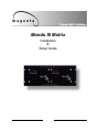
. Mondo III Matrix Installation & Setup Guide 1 MAGENTA MONDO MATRIX © 1998-2011 by Magenta Research All rights reserved. Magenta Research 128 Litchfield Road New Milford, CT 06776 USA This document and the Magenta Research products to which it relates, and the copyright in each, is the property of Magenta Research. Neither the document nor the products may be reproduced by any means, in whole or in part, without the prior written permission of Magenta Research. Magenta Research makes no warranty or representation, either express or implied, with respect to this software or documentation, including their quality, performance, merchantability, or fitness for a particular purpose. As a result, this software or documentation are licensed "as is" and you, the licensee, are assuming the entire risk as to their quality and performance. In no event will Magenta Research be liable for direct, indirect, special, incidental, or consequential damages arising out of the use of or inability to use the software or documentation. Magenta Research and the Magenta Research logo are trademarks of Magenta Research. All other brands, product names, and trademarks are the property of their respective owners. 2 FCC/IC RFI STATEMENTS, EU DECLARATION OF CONFORMIT, SAFETY WARNING.. FEDERAL COMMUNICATIONS COMMISSION AND INDUSTRY CANADA RADIO FREQUENCY INTERFERENCE STATEMENTS This device complies with part 15 of the FCC Rules. Operation is subject to the following two conditions: device may not cause harmful interference, and (2) this device must accept any interference received, including interference that may cause undesired operation. 1) This This equipment has been tested and found to comply with the limits for a Class A digital device, pursuant to part 15 of the FCC Rules. These limits are designed to provide reasonable protection against harmful interference when the equipment is operated in a commercial environment. This equipment generates, uses, and can radiate radio frequency energy and, if not installed and used in accordance with the instruction manual, may cause harmful interference to radio communications. Operation of this equipment in a residential area is likely to cause harmful interference in which case the user will be required to correct the interference at his own expense. Canada (ICES-003) notice: This Class A digital apparatus complies with Canadian ICES-003. Cet appareil numerique de la classe A est conforme a la norme NMB-003 du Canada. EUROPEAN UNION DECLARATION OF CONFORMITY Warning: This is a Class A product. In a domestic environment this product may cause radio interference in which case the user may be required to take adequate measures. Magenta Research (New Milford CT USA) declares under our sole responsibility that the product Mondo III System to which this declaration relates is in conformity with the following standard(s) or other normative documents: EN 55022:1998/A1:2000/A2:2003 Class A ITE emissions requirements (EU AS/NZS). EN61000-3-2:2006 Limits for harmonic current emissions (equipment input current up to and including 16A per phase). EN 61000-3-3:1995/A1:2001/A2:2005 Limitation of voltage fluctuations and flicker on lowvoltage supply systems for equipment with rated current up to and including 16A. EN60950-1:2006 Safety for Information Technology Equipment EN55024:1998/A1:2001/A2:2003 Immunity for ITE SAFETY WARNING Installation • This equipment is to be installed in a restricted access location. Connection • Not for direct connection to Telecommunication Network Circuitry (TNV) Power sources • This equipment should be operated only from the power source indicated on the product. This equipment is intended to be used with a main power system with a grounded (neutral) conductor. The third (grounding) pin is a safety feature, do not attempt to bypass or disable it. This equipment can be powered from redundant power sources. Disconnect all power sources before servicing. Power disconnection • To remove power from the equipment safely, remove all power cords from the rear of the equipment, or from the power source receptacle (wall plug). Note that this equipment has multiple power inputs. Power cord protection • Power cords should be routed so that they are not likely to be stepped on or pinched by items placed upon or against them. Servicing • Refer all servicing to qualified service personnel. There are no user-serviceable parts inside. To prevent the risk of shock, do not attempt to service this equipment yourself because opening or removing covers may expose you to dangerous voltage or other hazards. Slots and openings • If the equipment has slots or holes in the enclosure, these are provided to prevent overheating of sensitive components inside. These openings must never be blocked by other objects. Lithium battery • There is a danger of explosion if battery is incorrectly replaced. Replace it only with the same or equivalent type recommended by the manufacturer. Dispose of used batteries according to local laws. The battery stores configuration information in the event of a power failure. Contact manufacturer for battery replacement procedures. Battery is not intended to be a user serviceable part 1 3 MAGENTA MONDO MATRIX Contents Chapter Page 1. Specifications............................…...................................................................3 2. Overview & Design Guidelines….......….........................................................4 3. Installation…………........................................… ......................................….14 4. Configuration………........................................… ......................................….18 5. Commands.........................................................................................……....21 6. Mondo III SAP Design, Configuration, Usage....................................……....32 7. Troubleshooting…………………………………………………………………....35 Appendix A: Cable Pinouts..…………………………………………………………...36 Appendix B: Fan Filter Cleaning/Replacement……………………………………...39 Appendix C: Using the USB port on Mondo III SAP………………………………...40 24 CHAPTER 1: Specifications. 1 Specifications Video & Aux Signals: Signal configuration………………………4 , individually routable channels per RJ-45 jack. Input impedance.....................................100Ω balanced (Compatible with all MultiView equipment) Nominal input amplitude.........................1 Volt P-P Dynamic headroom ................................>3dB Gain from transmitter input to receiver output through switch ...…………………Unity Coupling from transmitter input to receiver output....…………………………DC Circuitry bandwidth .................................>220MHz Signal type ..............................................1,2,3,4 & 5 component video + aux channels (Via MultiView components) Input connectors (UTP)............................RJ-45 Female Input connectors (VGA)...........................HD15 female, 1/8” audio socket Loop out connectors.........................…....RJ-45 Female Output connectors…………………………RJ-45 female Audio: Audio signals are ported into the Mondo III Matrix via MutiView components or via a 3.5mm stereo audio jack for Mondo Direct. The type of transmitters and receivers used therefore defines audio specifications. Please refer to the spec sheets for those components. RS 232 Serial: Serial signals are ported into the Mondo III Matrix via MultiView components or via a 3.5mm audio jack for simplex transmit in a Mondo Direct. Transmission is uni-directional broadcast in this mode. Mondo III SAP versions allow bi-directional serial sessions with individual receivers. There are 8 DB9 COM ports on each Mondo III SAP frame That can be used in conjunction with SAP enabled receivers for full bi-directional RS232 communication with the device attached to the receiver. Reference Section 6 for SAP usage. Control: Protocol to switch…………………………RS-232/RS-422*, Selectable; 9600 baud standard, (rate selectable to 9600, 19,200, 38,400, 57,600, 115,200) 8 data bits, 1 stop bit, no parity, no flow control. Interface connector, input………….….….DB9 or 7 position Phoenix** Interface connector, input………….….….USB mini B type (Mondo III SAP ONLY. Requires driver file: MONDO3_USB.inf) Interface connector, Interframe communication, input/output………...3 position Phoenix or 7 position Phoenix (used for Mondo Legacy mode only)*** All input to output switching commands are received and processed by the master frame. Additional frames used within the matrix are connected in a daisy chain and receive processed commands from the master frame. In Mondo III serial control mode, the BUS terminator switch must be ON for the first and last frames. * The 7 pin phoenix serial input supports both RS-232 and RS-422 modes The DB9 serial ports support RS-232 only ** When using Mondo III frames in a legacy Mondo system only the 7 pin phoenix serial connections are used. *** The BUS connector and DB9 ports are disabled in this mode. Power: Power input .............................................100-240V / 50~60Hz Fused input. Replace fuse with same rating: 250V, 2.5A, Slow Blow, 5x20mm Consumption……………………………….200 W Max Redundancy………………………………..2 independent fully redundant AC Mains inputs. Environmental: Temperature/humidity Storage ………………………………...….-40° to +158°F (-40° to +70°C) / 10% to 90%, non-condensing Operating...........................………………...0° to +104°F (0° to +40°C) / 10% to 90%, non-condensing Mechanical: Rack mount ................................……..…Standard, 4U 19” EIA Enclosure type ..........................…………Front Panel: Powder coat over aluminum Enclosure: Aluminum Enclosure dimensions ......………………..7.0" H x 19" W x 10.25" D (178 mm H x 483 mm W x 260 mm D) Weight ................................…….………..16.6 lbs (7.5 kg) fully populated (shipping weight: 24 lbs (10.9 kg)) Compliances .............................…………CE, NRTL Listed, FCC Part 15 MTBF ......................................……….….100,000 hours 5 3 MAGENTA MONDO MATRIX 2. Overview / Design Guidelines 2.1 OverView The Mondo III Matrix CAT5 routing switch is a full matrix platform to easily distribute and route video, audio , and serial signals using the MultiView series of video over Cat5 products. It is available in configurations ranging from 16 inputs to 16 outputs up to 256 inputs to 512 outputs. New features of the Mondo III architecture are the following: Two independent AC Mains inputs for redundancy Filtered air cooling Improved serial communication Status indicators on the Front Panel Multiple serial port control SAP capability supported in Mondo III SAP versions for end-to-end bi-directional RS232 control of displays. Backwards compatibility with previous Mondo versions (not all features supported in legacy mode) NOTE: This manual covers the current release of the Mondo III Matrix switch. Previous versions of the Mondo matrix switch hardware are covered in previous user manuals. In order to utilize a Mondo III frame in a non-Mondo III environment see Section 4, Operational Mode command and Appendix A for legacy Mondo serial bus cabling. Contact Magenta Research for details. The Mondo Direct option allows a direct video connection (15HD VGA) into the Mondo Matrix without using a MultiView transmitter. An 1/8” stereo audio jack is available for audio inputs. This jack can also be configured for transmit only serial or SPDIF digital audio at time of purchase. RJ45 cascade loop throughs provide connections to subsequent slave frames. It is only required to have the Mondo Direct option on the first input frame. A maximum of 32 Mondo Direct inputs can be configured. It is possible to mix one Mondo Direct card and one or two standard Mondo RJ45 input cards as well. The Mondo III SAP version features up to 8 built-in RS 232 serial ports per frame that allow communication to SAP enabled MultiView receiver units. The Mondo III is controlled via an RS 232 interface either through a simple terminal program or any third party control systems. There are no manual or front panel control options for the Mondo III Matrix. An optional separate touch screen interface, Mondo TC, is also available. Contact Magenta Research for details. 46 CHAPTER 2: Overview/Design Guidelines. 2.2 Design Guidelines When designing or installing a Mondo III system, the following should be adhered to: Equalize all Cat5 Input Cables to the Mondo III Matrix All Cat5 cable inputs should be as equal as possible between source transmitter and Mondo III Matrix switch (This does not apply to Mondo Direct inputs with VGA inputs). Otherwise video quality may be affected when switching as cable compensation settings at the receiver will change due to cable lengths changing. This can be accomplished by measuring all Cat5 cables and ensuring they are within 30 ft (9m) of variance. Add service loops as necessary. Another option is to use the MorphIT Dual EQ option between the transmitter and switch input to normalize all cables to 0 ft prior to the switch. Contact Magenta for details. Cable Length Equalization Method 1: Normalize input cable lengths All Cat5 Cable lengths from source Transmitters to the Mondo III Input frame must be within a 30 ft (9m) variance. Add service loops as necessary. Cable Length Equalization Method 2: Using Morph IT Dual EQ card Cable Length = Zero ft Cable Length L Use the MorphIT Dual EQ card to remove cable lengths from source transmitter just prior to the Mondo III Matrix switch input. Each port on the Dual EQ card can remove 500 ft (152m) of cable length. Two ports may be cascaded to remove a maximum of 800 ft (244m) of cable length. 75 MAGENTA MONDO MATRIX CHAPTER 2: Introduction 2.2 Design Guidelines, cont. A 64 input by 16 output single frame matrix switch Inputs 1-16 Inputs 17-32 Inputs 33-48 Inputs 49-64 Mondo III Matrix Sizing Mondo III Matrix frames are available in 16 output sizes. Inputs may vary from 1 to 64 in 16 port increments. To add outputs, frames are cascaded “vertically” in “rows”. To add inputs beyond the 64 input single frame limit, frames are cascaded “horizontally” in “columns”. In the case of Mondo Direct frames, a maximum of 32 inputs is allowed. All frames must have the same number of input ports within a system. Add 16 outputs by cascading vertically in rows. The above switch is now a 64 input by 32 output two frame matrix switch. A maximum of 512 outputs are possible. Inputs 1-16 Inputs 17-32 Inputs 33-48 Inputs 49-64 Outputs 1-16 Outputs 1-16 Inputs 65-80 Inputs 81-96 Inputs 97-112 Add 16 to 48 inputs by cascading horizontally in columns. The above switch is now a 112 input by 32 output 4 frame matrix switch. A maximum of 256 inputs are possible. Inputs 1-16 Inputs 17-32 Inputs 33-48 Inputs 49-64 Outputs 17-32 Outputs 1-16 Outputs 1-16 Outputs 17-32 Outputs 17-32 6 8 CHAPTER 2: Overview/Design Guidelines. 2.2 Design Guidelines, cont. Eight Frame Cascade Limit All inputs to the Mondo III are cascaded to subsequent frames via Cat5 cascade loop throughs on each input card. It is recommended to loop through no more than 8 frames or video performance may be affected beyond 8 frames. If using more than 8 frames, the source signals must be split using multiple transmitters, cascading transmitters via the local monitor output frames, using T4 multi output transmitters, or the MultiView 9D Cat5 distribution amplifier. Using two single port transmitters to split the video via the local monitor port of the first transmitter: Video out of local monitor port to input of second transmitter Video In UTP UTP 8 Frames 8 Frames Using a T4 transmitter to feed input video to 8 frames at a time: Video In UTP UTP 8 Frames 8 Frames 97 MAGENTA MONDO MATRIX CHAPTER 2: Introduction 2.2 Design Guidelines, cont. Frame Addressing is Important All control of the Mondo III is input via the Master frame. In the Mondo III architecture, any frame can be configured to be the Master regardless of its address, but it is recommended to make the first frame addressed 00 to be the master. Master frames are set via the LCD. See Section 4 for details. There can only be one Master frame in a system. The Mondo III master frame intelligently configures itself when powered on by locating all other slave frames and based on a specific addresses can route switch commands to the correct frame. The master frame should be powered on last for this to occur. There is no need to configure the Mondo III beyond setting frame addresses if default serial port settings are used. If other serial port settings need to be configured or if using other serial input ports, please configure them according to instructions in Section 4. Please follow Table 1 on page 9 for address guidelines. Frame addressing is done via the LCD on the rear of the frame. See Section 4 for details. It is necessary to power cycle the frame to make the address change go into effect. The master frame also requires to be re-initialized when a slave frame address is changed or added. This can be accomplished using the #I command or a power reset. 64 input by 32 output two frame matrix switch. 2 Rows and 1 Column Frame Address 00 Frame Address 00 Outputs 1-16 Outputs 17-32 Inputs 1-16 Inputs 17-32 Inputs 33-48 Inputs 49-64 Frame Address 01 112 input by 32 output four frame matrix switch. Note address sequence in second column. Outputs 1-16 Inputs 65-80 Inputs 81-96 Inputs 97-112 1 Row and 1 Column Inputs 1-16 Inputs 17-32 Inputs 33-48 Inputs 49-64 64 input by 16 output single frame matrix switch. Inputs 1-16 Inputs 17-32 Inputs 33-48 Inputs 49-64 Following are some examples of frame addressing based on specific Mondo III Matrix sizes. Frame Address 00 Outputs 1-16 Frame Address 01 Outputs 17-32 2 Rows and 2 Columns 8 10 Frame Address 32 Frame Address 33 Outputs 1-16 Outputs 17-32 CHAPTER 2: Overview/Design Guidelines. 2.2 Design Guidelines, cont. Use the following table to determine the correct address assignments and Input Output connections for each switch frame. Note that Mondo III addressing has changed from legacy Mondo systems. For legacy Mondo frame addressing, refer to previous Mondo Matrix user guides. Table 1: Mondo III Matrix Frame Addresses COL1: INPUT 1- 64 COL 2: INPUT 65 - 112 COL 3: INPUT 113 - 160 COL 4: INPUT 161 - 208 COL 5: INPUT 209 - 256 OUTPUTS ROW 1: Addr 00 Addr 32 Addr 64 Addr 96 Addr 128 1 - 16 ROW 2: Addr 01 Addr 33 Addr 65 Addr 97 Addr 129 17 - 32 ROW 3: Addr 02 Addr 34 Addr 66 Addr 98 Addr 130 33 - 48 ROW 4: Addr 03 Addr 35 Addr 67 Addr 99 Addr 131 49 - 64 ROW 5: Addr 04 Addr 36 Addr 68 Addr 100 Addr 132 65 - 80 ROW 6: Addr 05 Addr 37 Addr 69 Addr 101 Addr 133 81 - 96 ROW 7: Addr 06 Addr 38 Addr 70 Addr 102 Addr 134 97 - 112 ROW 8: Addr 07 Addr 39 Addr 71 Addr 103 Addr 135 113 - 128 ROW 9: Addr 08 Addr 40 Addr 72 Addr 104 Addr 136 129 - 144 ROW 10: Addr 09 Addr 41 Addr 73 Addr 105 Addr 137 145 - 160 ROW 11: Addr 10 Addr 42 Addr 74 Addr 106 Addr 138 161 - 176 ROW 12: Addr 11 Addr 43 Addr 75 Addr 107 Addr 139 177 - 192 ROW 13: Addr 12 Addr 44 Addr 76 Addr 108 Addr 140 193 - 208 ROW 14: Addr 13 Addr 45 Addr 77 Addr 109 Addr 141 209 - 224 ROW 15: Addr 14 Addr 46 Addr 78 Addr 110 Addr 142 225 - 240 ROW 16: Addr 15 Addr 47 Addr 79 Addr 111 Addr 143 241 - 256 ROW 17: Addr 16 Addr 48 Addr 80 Addr 112 Addr 144 257 - 272 ROW 18: Addr 17 Addr 49 Addr 81 Addr 113 Addr 145 273 - 288 ROW 19: Addr 18 Addr 50 Addr 82 Addr 114 Addr 146 289 - 304 ROW 20: Addr 19 Addr 51 Addr 83 Addr 115 Addr 147 305 - 320 ROW 21: Addr 20 Addr 52 Addr 84 Addr 116 Addr 148 321 - 336 ROW 22: Addr 21 Addr 53 Addr 85 Addr 117 Addr 149 337 - 352 ROW 23: Addr 22 Addr 54 Addr 86 Addr 118 Addr 150 353 - 368 ROW 24: Addr 23 Addr 55 Addr 87 Addr 119 Addr 151 369 - 384 ROW 25: Addr 24 Addr 56 Addr 88 Addr 120 Addr 152 385 - 400 ROW 26: Addr 25 Addr 57 Addr 89 Addr 121 Addr 153 401 - 416 ROW 27: Addr 26 Addr 58 Addr 90 Addr 122 Addr 154 417 - 432 ROW 28: Addr 27 Addr 59 Addr 91 Addr 123 Addr 155 433 - 448 ROW 29: Addr 28 Addr 60 Addr 92 Addr 124 Addr 156 449 - 464 ROW 30: Addr 29 Addr 61 Addr 93 Addr 125 Addr 157 465 - 480 ROW 31: Addr 30 Addr 62 Addr 94 Addr 126 Addr 158 481 - 496 ROW 32: Addr 31 Addr 63 Addr 95 Addr 127 Addr 159 497 - 512 119 MAGENTA MONDO MATRIX 2.2 Design Guidelines, cont. Switching Individual Signals (Pairs) on a single input/output It is possible to switch individual pairs of the Cat5 switch inputs and outputs to one or different locations. This is useful when sending audio or serial signals from one source to locations that have different video sources. For example, a different source of video may be displayed while a single audio or serial signal is broadcast to one or more displays without changing the video signal. Reference the Batch Routing Command set in Section 5. See the table below for a reference chart for the signals MultiView places on individual pairs. Local Breakout of Signals It is possible to breakout source input signals such as video, audio, or serial by utilizing the last input card cascade loop outs to the appropriate Magenta receiver. Note that these signals do not pass through the switch. Video Out Audio/Serial Out 10 12 CHAPTER 2: Overview/Design Guidelines. 2.2 Design Guidelines, cont. Mondo III SAP Mode The Mondo III SAP option features up to 8 serial ports that can be configured as Mondo control ports or used in SAP mode. SAP mode offers the ability for bi-directional RS232 control of devices attached to SAP enabled receiver units. Reference Section 6, SAP Usage, for instructions on using SAP mode with the Mondo III Matrix. The Mondo III SAP option also features an additional USB control input that can be used with any serial terminal application on a PC. A software driver, MONDO3_USB.inf, is required to be installed on the host PC. This can be found on the accompanying CDROM or downloaded at http://www.magenta-research.com See diagram below for an explanation of the Mondo III serial ports. Non-Mondo III SAP systems do not have COM3—COM8 enabled and do not have the ability for SAP control or USB control. Mondo III SAP RS232 Inputs Com1 through Com8 Control or SAP capable Mondo III Control SAP version only. Requires software driver on host PC 13 11 MAGENTA MONDO MATRIX CHAPTER 2: Overview/Design Guidelines 2.2 Design Guidelines, cont. Controlling the Mondo III Matrix The Mondo III Matrix does not offer manual or front panel control options. All commands are input via an RS232 serial port on the master frame via a third party control system such as Calypso Control Systems, Crestron, or AMX. A remote control panel, the Mondo TC touchscreen, is also available as a control option. Contact Magenta Research for details. Additionally a simple terminal program such as Hyperterminal (available as part of the Windows operating system) may be used to send individual commands to the Mondo III. The Mondo III features multiple serial ports for various control options depending upon the version: Mondo III without the SAP option Features two DB9 COM ports that can be used for additional control options (note that ports COM1 and COM2 are only supplied on the first Mondo frame). The 7 pin phoenix connector labeled 1-7 may also be used as a control input COM port. Mondo III with the SAP option Features eight DB9 COM ports that can be used for additional control options or in SAP mode. The 7 pin phoenix connector labeled 1-7 may also be used as a control input COM port. A USB port can also be used with a PC serial terminal application. Interframe serial cabling utilizes the BUS connector labeled A,B, GND. This is a high speed serial bus system that has higher execution speeds. This bus is only compatible in Mondo III mode. A 7 pin phoenix output connector labeled 8-14 is provided for backwards compatibility with older Mondo systems. The Mondo III frame must be configured via the LCD to legacy mode for this connector to function. See Appendix A for cabling and Section 4 for LCD configuration. See Section 3 for cabling and connection diagrams. Mondo III Control Input (COM1 & COM2. Non-SAP versions. First frame only Contact Closure Used in ALARM mode. See command section Mondo III Control Input (COM1 through COM8. SAP versions. All frames. Mondo III Control SAP version only. Requires software driver on host PC Mondo III Interframe cabling (input) Mondo III Control Input and/or Legacy Mondo Interframe Cabling (input) Mondo III Interframe cabling (output) Legacy Mondo Interframe Cabling (output) Not used for Mondo III Mondo III Interframe Bus Termination switch. 12 14 . 2.2 Design Guidelines, cont. Front Panel Status Dashboard Each Mondo III frame features a front panel status panel that shows a frames current state with respect to power supply health, fan health, air filter service, internal frame temperature, system communications, and any alarm events. Indicators are detailed and explained below: PS1/PS2 – Power supply status indicator. The power supply generates two voltages: +5V and –5V. Both voltages are monitored and their status is shown here. 1. Solid Green: Power supply function is normal 2. Flashing Red: Both +5V and –5V voltages are off. 3. Solid Yellow: Either +5V or –5V is out of normal range or off. 4. Flashing Yellow: Both +5V and –5V voltages are out of normal range. FAN1/FAN2 – Cooling fan status indicator. The fan speed is monitored and the status is indicated here. 1. Solid Green: Fan is operating normally. 2. Flashing Red: Fan isn’t turning (locked rotor, bad fan motor). 3. Solid Yellow: Fan is turning too slow (bad bearings, bad fan motor). FILTER – Indicates filter status. The Mondo III features filtered air cooling. The filter is located on left side of the unit and is easily removable by simply sliding it out the rear of the unit. Please ensure the filter is cleaning periodically. See Appendix B for removal instructions. The interval is manually configured via the LCD and is not automatic. 1. Solid Green: filter does not require service. 2. Solid Red: Filter requires service. ALARM – Indicates an alarm condition if any of the system elements shown on the dashboard are not operating normally. This is also linked to the dry contact (Form C) ALARM output for remote alarm monitoring (only power supply, temperature and fan failure affect the ALARM indicator and dry contact closure) 1. Solid Green: no alarms, system is functioning normally. 2. Solid Red: Alarm state, one or more system elements are not operating correctly or need service. COMMS – Indicates communication and link port activity. 1. Off: No communication port activity. 2. Solid Blue: Main Control port or auxiliary serial port activity. 3. Solid Green: Frame bus link activity (Mondo 3 mode) or Slave frame control port activity (Mondo 2 mode). Note: In a multiple frame Mondo III system, all COMMS indicators should be green when the system is idle. A dark indicator indicates a bad or disconnected bus link cable. A single Master frame however will not show a green indicator because nothing is connected to the bus link. Note: In Legacy Mondo mode, the indicator will only turn green on Slave frames when a switch event occurs. If the indicator does not illuminate during switch commands, check for a bad or disconnected inter-frame communications cable. TEMP – Indicates temperature 1. Solid Green: Temperature is within allowable range. 2. Flashing Yellow: Temperature is 38 degrees C or higher. 3. Flashing Red: Temperature is 42 degrees C or higher. 15 13 MAGENTA MONDO MATRIX CHAPTER 3: Installation 3. Installation 1. Install the Mondo III Matrix switch frames in a suitable rack fixture. The Mondo III Matrix is designed to install into a standard 19” wide cabinet. It is recommended to install all Mondo III Matrix hardware in a restricted access location such as a secure equipment room. Ensure there is adequate ventilation space on side and rear of unit. It is not necessary to allow ventilation space above or below each frame. WARNING This equipment is not intended for, nor does it support, distribution through an Ethernet network. Do not connect these devices to any sort of networking or telecommunications equipment! Not for direct connection to the telecommunication network circuitry (TNV) This equipment is to be installed in a restricted access location only. Product may be powered by redundant power sources. Disconnect all power sources before servicing. 2. Before any cables are connected, determine the Input / Output assignments for each switch frame. The address assigned to the switch frame determines the Input / Output range in the Mondo III Matrix system. See Table 1 in Section 2.2 for frame address schemes. If the Mondo III SAP option has been purchased, ensure the frames with the SAP COM ports are in the last column. Reference Section 6, Mondo III SAP Usage. 3. Apply power to each individual Mondo III Matrix frame and verify (or assign) proper switch frame addresses according to intended Input / Output assignments. Each switch frame must have a unique address. Use the configuration LCD to configure the address. Press the MENU button until FRAME ADDRESS is shown. The Press UP/DOWN buttons to change address if necessary. Finally press the OK button to save changes. See Section 4 for details on other configuration parameters. Frame Address: 000 14 16 . 3. Installation (cont) 4. Depending on the version purchased, switch frames may have multiple sets of I/O Comm Ports. COM1 through COM8 are standard DB9 RS-232 interfaces that may be connected to a third party control system or the Mondo TC touch panel control unit (these COM ports need to be configured and set via the LCD for control mode. See Section 4, Configuration). The 7 pin captive screw connector labeled 1-7 is typically used to connect to a third party control system and is always enabled. The 3 pin Phoenix IN/OUT connection labeled BUS is for interframe serial communication. This connection is only utilized in Mondo III mode and not enabled in Legacy Mondo mode. In legacy Mondo systems, please use the 7 pin IN/OUT Phoenix connectors for interframe communication (see Appendix A for cable pinouts). 5. Connect the control cable (RS-232) between the controller device (PC or third party control system) and the Master switch frame desired COM port. It is recommended to use the 7 pin phoenix connector for this application. 6. Connect interframe bus cables between each frame. Remember to set the BUS TERM switch to ON for the first and last frames and ensure it is OFF for middle frames. Frames do not need to be cabled in any particular order as long as the first and last frames have the BUS term ON and all other frames have BUS term OFF. These COM ports may also be used for third party control applications BUS TERM switch must be ON for first and last frames and OFF for middle frames To Control Application This connection only used in Legacy Mondo systems 17 15 MAGENTA MONDO MATRIX CHAPTER 3: Installation 3. Installation (cont) 7. Connect Cat5 Input Loop cables between switch frames as required. Insert RJ45 cables gently — pushing too hard may damage connector pins. Ensure cables “click” securely into place. 8. Connect Cat5 Input cables from source devices to Mondo II Matrix inputs. Insert RJ45 cables gently — pushing too hard may damage connector pins. If a Mondo Direct input card is used, connect video sources directly into the HD15 connectors. Ensure cables “click” securely into place. 9. Connect Cat5 Output cables from Mondo III Matrix outputs to destination devices. Insert RJ45 cables gently — pushing too hard may damage connector pins. Ensure cables “click” securely into place. Figure 3-2: UTP Cabling Examples UTP In/Out Mondo Direct 16 18 . 3. Installation (cont) NOTE It is recommended to maintain cable lengths as equal as possible from each transmitter unit to the switch. This is due to all adjustments for cable length compensation are done on receiver units. Switching between inputs with unequal cable lengths may cause display images to change due to incorrect cable compensation settings on the receiver. The Morph-It Cable EQ option can be used to add/subtract cable lengths. Contact Magenta Research for details Figure 3-2: UTP Cabling Examples Adding Inputs beyond 64 9. Apply power to the Mondo III Matrix system. It is recommended that power is applied simultaneously to all switch frames. If this is not practical, then apply power to Slave switch frames first, then power up the Master switch frame. 10. Mondo III is intended to be controlled via a third party application such as AMX or Crestron. Instructions on control packages is beyond the scope of this document. For troubleshooting purposes, it is recommended to use a simple terminal control program such as Hyperterminal. See Section 4 and 5 for set up and commands. 19 17 MAGENTA MONDO MATRIX CHAPTER 4: Configuration 4. Configuration The Mondo III Matrix setup and configuration parameters are accessible via the rear LCD screen. Four buttons are used to select, view and/or change parameters. Figure 4-1 shows the locations and functions of the controls. The following explains each setup screen as well as its possible values. After 10 seconds of inactivity within a setup screen, the Mondo III Matrix will exit setup mode and display the Default Status screen or a user defined status screen. NOTE: When advancing through the settings with the OK button, ensure that you go through all fields for a menu item until the LCD displays “ Settings Saved”. Otherwise the changes will not be permanently saved. Figure 4: Mondo III configuration LCD MENU button Cycles through the various configuration parameters UP/DOWN buttons: Cycles through options for a given parameter. OK button: Press to accept parameter value 1. Default / Status – Displays the firmware version on line one (top) and the Frame Address and Operational Mode on the second line (bottom). This is the “idle” display screen. · The “UP” and “DOWN” buttons may be used to adjust the display contrast. · The “OK” button will save the current LCD display contrast setting so that it will be restored after a power cycle. Note: During system initialization after a power-up condition, slave frames will display an asterisk next to the operational mode. Once the Slave frame is detected by the Master, the asterisk will disappear: 2. Software Version Info – shows boot-loader version and application code version. There is no configurable parameter in this screen – it is purely informational. 3. Operational Mode – Displays the operational mode selection. · The “UP” and “DOWN” buttons may be used to select the mode. · The “OK” button will save the current mode. · Options are: M2 (Legacy Mondo), M3-S (Mondo III Slave) and M3-M (Mondo III Master). 18 20 . 4. Configuration (cont) 4. Frame Address – Displays the frame address. · The “UP” and “DOWN” buttons may be used to select the address. · The “OK” button will save the current address. 5. Alarm Sound – Displays the alarm sound configuration. When the Alarm sound is enabled, it will work in conjunction with the relay alarm module and the front panel dashboard. · The “UP” button will enable the audible alarm. · The “DOWN” button will disable the audible alarm. · The “OK” button will save the current setting. 6. Filter Service – Displays the filter service interval. · The “UP” and “DOWN” buttons may be used to select the filter service interval. · The “OK” button will save the current setting. · Setting the interval to “255” will disable the filter service warning (the interval will stay at “255” unless it is changed manually. 7. Com 1– 8 Setup – Displays the setup parameters for each installed Com in succession (aux. serial port). · There are several parameters that need to be configured but only one will be active at a time. The active parameter will blink. · The “UP” and “DOWN” buttons may be used to select parameter values. · The “OK” button will select the next parameter. When the last parameter has been configured, it will save the current setting (“Setting Saved” will be shown). Parameters: 1. Mode – Port mode selection: a. Mode 0 = Port disabled. b. Mode 1 = Command port (accepts switch control commands). c. Mode 2 = Command port with event notification. Same as mode 1 but every time a switch cross-point assignment changes, an event notification (‘!M”)* will be issued. c. Mode 3 = SAP mode (Mondo III SAP ONLY). Requires SAP enabled receivers. 2. Baud Rate – Baud rate selection (only available if the port is enabled). 3. Auxiliary Power configuration. (only available if the port is enabled, otherwise it will be turned off automatically).Turning Aux. power on will supply +5VDC / 100mA on pin 9 of the DB-9 connector. Use with caution. It is recommended that only one serial port have this enabled * The “!M” event notification (!M<LF><CR>) is sent any time a change is made to the switch matrix. This can be useful when multiple control points are used to control the Mondo III Matrix as a method to determine when a change has occurred. It is suggested to query the switch crosspoint status with the D, #D or #M commands after this event notification is received to update any control system menus. See the $SPC command in Section 5. 21 19 CHAPTER 4: Configuration MAGENTA MONDO MATRIX 4. Configuration (cont) 8. Com 9 Setup – Displays the setup parameters for Com 9 (auxiliary serial port #9, 7 pin phoenix connector labeled 1-7). · There are several parameters that need to be configured but only one will be active at a time. The active parameter will blink. · The “UP” and “DOWN” buttons may be used to select parameter values. · The “OK” button will select the next parameter. When the last parameter has been configured, it will save the current setting. · Com 9 is always enabled so Mode 0 is not a valid selection. Parameters: 1. Mode – Port mode selection (Mode 0 and 3 are not valid for Com 9): a. Mode 1 = Command port (accepts switch control commands). b. Mode 2 = Command port with event notification. Same as Mode 1 but every time a switch cross-point assignment changes, an event notification (“!M”)* will be issued. c. 2. Baud Rate – Baud rate selection (only available if the port is enabled). 3. Serial Interface Mode (RS232, RS422). * The “!M” event notification (!M<LF><CR>) is sent any time a change is made to the switch matrix. This can be useful when multiple control points are used to control the Mondo III Matrix as a method to determine when a change has occurred. It is suggested to query the switch crosspoint status with the D, #D or #M commands after this event notification is received to update any control system menus. See the $SPC command in Section 5. 20 22 . 5. Commands Mondo III Matrix Serial Communications Requirements: 9600 Baud (default baud rate, selectable via LCD menu. See Chapter 4) 8-bit, No Parity, One Stop Bit No Handshaking is required Characters sent to the Mondo III Matrix are not echoed back to the controller. If using a simple terminal application, enable the local echo option. The Mondo III Matrix will reply with either “OK>“ (command accepted) or “ERxx>“ (error, command not recognized) after a command string is sent. Error codes are: ER00 = Reserved ER01 = Reserved ER02 = Error, command not recognized or executed ER03 = System locked. Try again later Note that all commands are terminated with a carriage return <CR> (0A hex). The Mondo III Matrix responds back with data output terminated with <LF><CR> characters (0D hex, 0A hex). An entire command string may be sent without any character pacing delays, however it is recommended to wait for the “OK>“ ready prompt from the switch before sending the next command string. The Mondo III Matrix master frame outputs information on its hardware and firmware platform as well as how many frames are connected at power up. This can be useful to troubleshoot Mondo III Matrix communication errors and how many frames the master has found. Following is the complete Mondo III Matrix Command set (commands designated with an M3 note are only supported in Mondo III mode and with Mondo III frames): General Commands: #C = Clear all output assignments - sets all Outputs to OFF (routes to input 0). #I = Initialize system. Master frame will detect slave frames and restore power up crosspoint map. Similar to power cycling the master frame. S = Save current crosspoint map into memory. This map is restored after power up or when the #I or R command is given. R = Restore power on crosspoint map. #$ = Enable Auto-Save: Current cross-point map is saved into memory and will be restored at power up, or if an #I, R command is received #& = Disable Auto-Save: Current cross-point map will not be saved into memory 23 21 MAGENTA MONDO MATRIX CHAPTER 5: Commands 5. Commands, cont. General Commands (cont): D = Displays entire crosspoint map of the system Displays format of xxx Vyyy A zzz Where xxx is output number, Vyyy is UTP pairs 1,2,3 and Azzz is UTP pair 4 #D = Extended Crosspoint map of the system Switch will respond with a list of outputs and the inputs connected to them: zzz Rvvv Gwww Bxxx Ayyy Where: Zzz = Output number vvv = "Red" channel Input assignment (UTP pair 2) www = "Green" channel Input assignment (UTP pair 3) xxx = "Blue" channel Input assignment (UTP pair 1) yyy = "Audio / Aux." channel Input assignment (UTP pair 4) #Dzzz = Report a single output cross point (M3 only) Switch will respond with a list of inputs connected to the specified output (zzz): zzz Rvvv Gwww Bxxx Ayyy Where: zzz = Output number specified vvv = "Red" channel Input assignment (UTP pair 2) www = "Green" channel Input assignment (UTP pair 3) xxx = "Blue" channel Input assignment (UTP pair 1) yyy = "Audio / Aux." channel Input assignment (UTP pair 4) #M = Cross-point map of selected Input / source #Maaa(Enter) Switch will respond with a list of outputs that are connected to the selected input: zzz Vxxx Ayyy Where: aaa = Input xxx = Video Input assignment yyy = Audio / Aux. input assignment zzz = Output Since it is possible to route video and audio / aux. signals separately, the reply must be analyzed to determine exactly which signals are routed to the selected input. The output will only be included in the list if one or both signals are routed to the selected input. If no outputs are assigned to the selected input, the switch will issue the ready prompt only (OK>). #T = Report Temperature in Celsius (Master frame only.) 22 24 . 5. Commands, cont. Standard Routing Commands: B = Both Video and Audio V = Video Only (UTP pairs 1,2,3) A = Audio Only (UTP pair 4) Parameters: xxx = Output yyy = Input (If yyy=0 then the output will be turned off) Note: Output (xxx) may be 1-3 digits, Input (yyy) may be 1-3 digits, however both must be the same number of digits (append leading zeros if required). Examples: Bxxxyyy<CR> Or Vxxxyyy<CR> Or Axxxyyy<CR> B1314<CR> Audio and Video from Input 14 are routed to Output 13. V86<CR> Video from Input 6 is routed to Output 8. A1412<CR> Audio from Input 12 is routed to Output 14. To turn an output off, route from Input 00 Example: B1600<CR> turns output #16 off. Q = Mix Video and Audio Parameters: XXX=Output YYY=Input Video (UTP pairs 1,2,3) ZZZ=Input Audio (UTP pair 4) Note: Output (xxx) may be 1-3 digits, Video Input (yyy) may be 1-3 digits, Audio Input (zzz) may be 1-3 digits, however all must be the same number of digits (append leading zeros if required). Examples: Qxxxyyyzzz<CR> Q011213<CR> Video from Input 12 and Audio from Input 13 is routed to Output 1. 25 23 CHAPTER 5: Commands MAGENTA MONDO MATRIX 5. Commands, cont. Salvo Routing Commands: X = Salvo Both Video and Audio Y = Salvo Video Only (UTP pairs 1,2,3) Z = Salvo Audio Only (UTP pair 4) Parameters: mmm = First Output in range nnn = Last Output in range ooo = Input number Note: First Output (mmm) may be 1-3 digits, Last Output (nnn) may be 1-3 digits, Input (ooo) may be 1-3 digits, however all must be the same number of digits (append leading zeros if required). Examples: Xmmmnnnooo<CR> Or Ymmmnnnooo<CR> Or Zmmmnnnooo<CR> X121508<CR> Send Video and Audio from Input 8 to Outputs 12 through 15. Y123<CR> Send Video Only from Input 3 to Outputs 1 and 2. Z010516<CR> Send Audio Only from Input 16 to Outputs 1-5. Conference Mode (Cross Connect) Commands: J=Both Video and Audio K=Video Only (UTP pairs 1,2,3) L=Audio Only (UTP pair 4) Parameters: xxx = Output yyy = Input Note: Output (xxx) may be 1-3 digits, Input (yyy) may be 1-3 digits, however both must be the same number of digits (append leading zeros if required). Examples: Jxxxyyy<CR> Or Kxxxyyy<CR> Or Lxxxyyy<CR> J1215<CR> Route Both Audio and Video from Input 15 to Output 12 and Input 12 to Output 15 K1215<CR> Route Video Only from Input 15 to Output 12 and Input 12 to Output 15 L1215<CR> Route Audio Only from Input 15 to Output 12 and Input 12 to Output 15 24 26 . 5. Commands, cont. Batch Routing Commands: E = Both Video and Audio F = Video Only (UTP pairs 1,2,3) G = Audio Only (UTP pair 4) EE = Take (Execute Batch Commands) Parameters: xxx = Output yyy = Input (If yyy=0 then the output will be turned off) Examples: Exxxyyy<CR> E1211<CR>F1112<CR>G1405<CR>F0812<CR>EE<CR> As a batch do the following after receiving the EE command: Route Both Audio and Video from Input 11 to Output 12 [E1211] Route Video Only from Input 12 to Output 11 [F1112] Route Audio Only from Input 05 to Output 14 [G1405] Route Video Only from Input 12 to Output 08 [F0812] Execute [EE] #R #G #B #A EE = = = = = Red Channel (1st Pair) Green Channel (2nd Pair) Blue Channel (3rd Pair) Auxilliary Channel (4th Pair) Take (Execute Batch Commands) Parameters: xxx = Output yyy = Input (If yyy=0 then the output will be turned off) Examples: #Rxxxyyy<CR> Or #Gxxxyyy<CR> Or #Bxxxyyy<CR> Or #Axxxyyy<CR> #R11<CR>#G11<CR> #B11<CR>EE<CR> As a batch do the following after receiving the EE command: Route Red Channel Input 1 to Red Channel Output 1 Route Green Channel Input 1 to Green Channel Output 1 Route Blue Channel Input 1 to Blue Channel Output 1 Execute [EE] #R0116(Enter)#G0116(Enter)#B10(Enter)#A10(Enter)EE(Enter) As a batch do the following after receiving the EE command: Route Red Channel Input 16 to Red Channel Output 1 Route Green Channel Input 16 to Green Channel Output 1 Turn Blue Channel Output 1 OFF Turn Auxilliary Channel Output 1 OFF Execute [EE] 27 25 MAGENTA MONDO MATRIX CHAPTER 5: Commands 5. Commands, cont. New Mondo III Matrix Reporting & Configuration Commands: The following commands are not supported in legacy Mondo systems. $GEO - System Geometry (M3) Read system geometry: Command: Response: xxx = yyy = ii = mm = $GEO<CR> xxx,yyy,ii,mm<LF><CR> OK><LF><CR> Total number of input ports. Total number of output ports. Number of inputs per frame (16, 32, 48 or 64 are the only valid choices). Frame address of the master-frame in this system. $RTD - Report temperature data (M3) Report temperature data, all frames: Command: (One line for each frame) Response: Report temperature data, one frame: Command: (One line for each frame) Response: $RTD<CR> frame,ttt<LF><CR> frame,ttt<LF><CR> OK><LF><CR> $RTDframe<CR> frame,ttt<LF><CR> OK><LF><CR> frame = frame address 0..159 ttt = Temperature, in degrees Celcius. The temperature value itself can be 1 to 3 digits long, and will have a leading “+“ or “-“ sign. 26 28 . 5. Commands, cont. New Mondo III Matrix Reporting & Configuration Commands: $RFD - Report fan/filter data (M3) Report fan / filter data, all frames: (One line for each frame) Command: Response: $RFD<CR> frame,a,b,c,d,e<LF><CR> frame,a,b,c,d,e<LF><CR> OK><LF><CR> Command: Response: $RFDframe<CR> frame,a,b,c,d,e<LF><CR> OK><LF><CR> Report fan / filter data, one frame: frame = frame address 0..159 a= Fan-1 status code b= Fan-1 RPM c= Fan-2 status code d= Fan-2 RPM e= Filter status code Fan status codes: 0 = fan operation normal 1 = locked rotor, or complete fan failure detected. 2 = fan speed unusually slow (bearing failure?) 3 = fan speed unusually fast (air filter dirty?) Air filter status codes: 0 = filter OK. 1 = not implemented. 2 = filter needs changing now. 3 = not implemented. The response is always in groups of 5 fields, with a comma as the delimiter. One group for every active frame in the system. $FSI – Filter Service Interval, all frames (M3) Read days remaining, all frames : Command: (One line for each frame) Response: $FSI<CR> frame,n<LF><CR> frame,n<LF><CR> OK><LF><CR> Set filter service interval: Command: Response: $FSIframe,n<CR> OK><LF><CR> frame = frame address 0..159, Use * for setting filter service interval on all frames at once. n= Days until next filter-service interval. If read as “0” filter must be serviced immediately. By setting a new interval, it resets the day-countdown clock too. Note: to disable the filter service warning / alarm, set the service interval to “255”. 29 27 MAGENTA MONDO MATRIX CHAPTER 5: Commands 5. Commands, cont. New Mondo III Matrix Reporting & Configuration Commands: $RST – Reset System, all frames (M3) Reset (soft): Command: Response: $RST0<CR> OK><LF><CR> (then system resets) Reset (hard): Command: Response: $RST1<CR> OK><LF><CR> (then system resets) Command: Response: $RST2<CR> OK><LF><CR> (then system resets) Reset & full default: Soft-Reset: Similar to a power-up reset. All previous settings & configuration info are retained. Hard-Reset: Clears all configuration parameters except system geometry and web-interface parameters. Reset & Factory Default: Clears all settings and configuration parameters. This will also disable your auxiliary serial ports (COM1,2). USE WITH CAUTION! $SSP – System Status Panel (M3) Read status panel, all frames: (One line for each frame) Command: Response: $SSP<CR> frame,aabbccddeeffgghh<LF><CR> frame,aabbccddeeffgghh<LF><CR> OK><LF><CR> Command: Response: $SSPframe<CR> frame,aabbccddeeffgghh<LF><CR> OK><LF><CR> Read status panel, one frame: frame = aabbccddeeffgghh = frame address 0..159 Hex-digits, one byte for each status indicator (left to right) with a mask for the color and blink state: 01 = Blu 02 = Grn 04 = Red 08 = Blink examples: Off = 00 blue on = 01 green on = 02 red on = 04 yellow on = 06 blinking yellow = 0E blinking red = 0C 28 30 . 5. Commands, cont. Reporting/Configuration Commands: $LSF – Lock System Functions (M3) This command locks the serial ports from controlling the switch in a multi-user system. This is necessary so that significant switch configuration changes can all be accomplished without interruption by one user. An “unlock” event will occur after a two minute timeout. The serial port being used to submit this command is not affected (or you might lock yourself out!). Serial port lockout: Command: Response: x= $LSF0,*,*,x<CR> OK><LF><CR> 0 = unlock, 1 = lock Note: There is a 2 minute timeout on this command within the CPU firmware, in case the “unlock” command gets lost. If a user at another port tries to interact with the switch, that user will receive an “ER03>” response until the system is unlocked. That user will need to retry that command later. ALM – Alarm Control (M3) Enable/Disable/Mute the audible alarm. This command affects all frames in the switch matrix. Disable alarms: Enable alarms: $ALM0 $ALM1 $RSV – Report Software Versions (M3) Command: (One line for each frame) Response: $RSV<CR> version info string<LF> <CR> OK><LF><CR> Version info string: frame,bootloader,application,SAP bootloader,SAP application frame = frame address bootloader = CPU board bootloader version application = CPU application code version SAP bootloader = SAP board bootloader version SAP application = SAP application code version One group of three fields are transmitted for every frame in the current system. At the end of every group there is one <LF> and one <CR>. Absent frames will not be included in the response string. 31 29 MAGENTA MONDO MATRIX CHAPTER 5: Commands 5. Commands, cont. Reporting/Configuration Commands: $RPS – Report Power Status (M3) Status of all frames: Command: Response: $RPS<CR> status info string<LF><CR> status info string<LF><CR> OK><LF><CR> Command: Response: $RPSframe<CR> status info string<LF><CR> OK><LF><CR> Status of one frame: frame = Frame address Status info string: frame,PS1+,PS1-,PS2+,PS2-,BP+,BP-<CR> OK> frame = frame address PS1+ = Power-supply1, +5V rail voltage PS1- = Power-supply1, -5V rail voltage PS2+ = Power-supply1, +5V rail voltage PS2- = Power-supply1, -5V rail voltage BP+ = Backplane, +5V rail voltage BP- = Backplane, -5V rail voltage The voltage value will be in the format of “+5.00” or “-5.00”, where 5.00 is replaced by the actual reading. A failed supply rail will be reported as “0.00”. 30 32 . 5. Commands, cont. Reporting/Configuration Commands: $SPC – Serial Port Configuration (M3) For all baud-rates, the serial port data format is fixed at 8 data bit, no parity, 1 stop bit. Set port parameters: Command: Response: $SPCf,n,b,x,m<CR> OK><LF><CR> Command: Response: $SPCf,n<CR> f,n,b,x,m<LF><CR> OK><LF><CR> Command: Response: $SPCf<CR> 0,1,b,x,m<LF><CR> 0,2,b,x,m<LF><CR> ... 0,9,b,x,m<LF><CR> OK><LF><CR> Command: Response: $SPC<CR> 0,1,b,x,m<LF><CR> 0,2,b,x,m<LF><CR> ... 159,9,b,x,m<LF><CR> OK><LF><CR> Read one port’s settings: Read one frame’s settings: Read all port settings: f= n= b= x= m= Frame address, 0 to 159 (current range for 256x512 maximum system) Serial port channel: 1 = COM1, 2 = COM2, etc. 9 = COM9 (the 7 pin phoenix connector labeled 1-7) “link in” RS-232 port) Baud rate: 0 = 9600 1 = 19200 2 = 38400 3 = 57600 4 = 115200 Auxiliary parameter: COM1-8: aux-power output control: 1 = on, 0 = off (only enable on one port at a time). Max of 5VDC, 100mA. COM9: H/W interface select: 1 = RS-422, 0 = RS-232 Mode: 0 = Port disabled 1 = Control port 2 = Control port with event notification. This mode will send unsolicited event notifications whenever a new input / output assignment takes place. (See event notification !M notes under COM x LCD Setup in Section 4) 3 = SAP data mode (see Section 6) Note: COM9 (the 7 pin phoenix connector labeled 1-7) can never be disabled (Mode 0 is invalid) Note: The $SPC command can also be used to determine how many serial ports are active and available on each frame. 33 31 MAGENTA MONDO MATRIX CHAPTER 6: Mondo III SAP Design, Configuration and Usage 6. Mondo III SAP Design, Configuration and Usage The Mondo III SAP option enables up to 8 serial COM ports on the Mondo Matrix to establish bi-directional serial sessions with SAP enabled receivers. This can be used for turning displays on or off, querying displays for information such as status and other statistics. The SAP serial option simply establishes a path fully bi-directional path between a controlling application and a serial device at the receiver. The SAP option does not directly communicate with a serial device nor does it directly control a serial device. SAP enabled receivers are required for the Mondo III SAP option to function. In order to setup and use the SAP protocol option, please follow the guidelines below: Mondo III SAP design, configuration, and usage guidelines: Design Guidelines: The Mondo III SAP enabled frames feature 8 active DB9 COM ports. Non-SAP frames will not have any of these COM ports installed. These frames must be installed on the last column of the system to function correctly. In the case of a single column (input size less then 64 inputs) all frames should have the SAP serial port option. 64 input by 32 output two frame matrix switch. 2 Rows and 1 Column Inputs 1-16 Inputs 17-32 Inputs 33-48 Inputs 49-64 This is required due to the way the SAP feature is enabled. The SAP feature utilizes the fourth pair of the cat5 cable to send the serial signals to a receiver. The SAP enabled receiver receives these commands and passes them out through its serial port to the device. Return data is passed back to the Mondo III SAP frame and out of the COM port in use. If the Mondo III SAP frame is not in the last column, return serial data cannot pass through the system. Mondo III SAP frames with COM ports are installed in the last column Frame Address 00 Outputs 1-16 SAP frames in first column Frame Address 01 Inputs 65-80 Inputs 81-96 Inputs 97-112 Inputs 1-16 Inputs 17-32 Inputs 33-48 Inputs 49-64 112 input by 32 output four frame matrix switch. Note address sequence in second column. Outputs 17-32 Frame Address 00 Outputs 1-16 Frame Address 01 Outputs 17-32 2 Rows and 2 Columns SAP frames in second column Frame Address 32 Frame Address 33 Outputs 1-16 Outputs 17-32 The SAP option also allows stereo audio signals to be shared with the RS232 serial signal. Normally in a nonswitched environment, all signals input to the transmitter are sent to the receiver all at once on the fourth pair. In order to utilize the SAP stereo audio feature, SAP enabled transmitters are required. 32 34 CHAPTER 6: Mondo III SAP Design, Configuration and Usage. 6. Mondo III SAP Design, Configuration and Usage (cont) However, since the Mondo III SAP option uses the fourth pair to transmit bi-directional serial sessions, the stereo audio signal will be interrupted while a SAP serial session is in progress. To restore the audio signal, please remember to disconnect the SAP serial session on the Mondo when finished. See Mondo III SAP Usage later in this section. The Mondo III SAP feature is designed to connect a single serial COM port on the Mondo matrix frame to a single output at a time. It is not possible to connect a Mondo III SAP COM port to two or more outputs simultaneously. However, it is possible to connect individual COM ports to individual Mondo outputs at once. It is possible to connect a Mondo III SAP COM port on one frame to an output on another frame. Use with caution as the serial data is placed on the Mondo interframe protocol bus and transmission time can be affected. Return data from a receiver is delayed when doing this. Simultaneous broadcast streams to all outputs at once (such as a system wide “turn display ON command” ) is also not possible due to the Mondo III SAP protocol architecture. If it is necessary to configure transmit only serial signals to multiple Mondo III outputs, a separate SAP enabled transmitter should be utilized outside of the Mondo III SAP system and used for uni-directional transmit only commands utilizing the fourth pair switching feature of the Mondo Command protocol. Configuration Guidelines: In order to utilize the SAP features on the Mondo III SAP, frames with the COM ports in the last column must be set to SAP enabled. This done via the LCD on the rear of the frame. Scroll through the LCD option until the COM x setup is reached (x is COM1— COM8). To set a COM port to SAP enabled, set the first COM parameter to M3 (Mode 3). It is not necessary to have all ports set to the same Mode. Reference Section 4 on the LCD configuration parameters. Once a COM port is set to Mode 3, it cannot be used to control the switch itself. Connect a serial control cable from the controlling application to the desired COM ports. This is a separate connection used for serial transmission to SAP receivers. It cannot be used to control the Mondo system. Next ensure all SAP receivers have a valid non-zero address (reference SAP section in the respective receiver user guide). Do not set any receiver address to zero (0) as this is a reserved address for transmitters and will not allow the receiver to return serial data. Note that if there are only single receivers on individual Mondo outputs, they may all be addressed the same. If there are any daisy chained receivers on any Mondo outputs, they must have unique addresses. For simplicities sake, it is recommended that the first receiver on a Mondo output be addressed as ‘01’, the second (if daisy chaining is used) should be number ‘02’, etc. Finally, it is important to know the actual Mondo III frame address that all SAP enabled COM ports are on as this information is required in order to issue the SAP port switch command to the Mondo III Matrix system. 35 33 MAGENTA MONDO MATRIX CHAPTER 6: Mondo III SAP Design, Configuration and Usage 6. Mondo III SAP Design, Configuration and Usage (cont) Usage Guidelines: In order to use the Mondo III SAP option, first, the Mondo Matrix must be issued the SAP Control Command ($SCC) to switch the appropriate COM port to the appropriate Mondo Matrix output. It is important to wait for the Mondo Matrix to respond with the OK> prompt or wait 2-3 seconds before sending serial data to the receiver through the COM port. After this occurs then serial data may be transmitted between the Mondo III SAP COM port and the attached receiver. This connection will stay open until a SAP disconnect command is sent or another output is connected to the same COM port. See below for the Mondo III SAP Control command parameters. It is important to always issue the SAP disconnect (clear) command on the COM port just used before connecting it to another output. $SCC – SAP Control Command (Mondo III SAP option only) Connect a COM port to a SAP output: Command: $SCCp,a,f,c<CR> Response: OK><LF><CR> Read a SAP output COM port connection: Command: $SCCp,? <CR> Response: p,a,f,c<LF><CR> OK><LF><CR> Read all SAP output COM connections: Command: $SCC*,?<CR> or $SCC<CR> Response: p,a,f,c<LF><CR> ... p,a,f,c<LF><CR> OK><LF><CR> Clear a COM port connection: Command: $SCCp<CR> Response: OK><LF><CR> Clear all COM port connections: Command: $SCC*<CR> Response: OK><LF><CR> Where: p= Select output port number (1..512) for SAP communications. This is the Mondo Matrix output number a= Device address, 1..255 (0 = all devices on this port). This is the SAP receiver address (see SAP section in receiver user manual). f= Frame number for the specified serial port (0..159, typically). This is the Mondo frame address set in the LCD configuration screen that the COM port is located c= COM: port to connect with (1..8). Ensure this port is set to Mode 3 via the LCD configuration screen. on. Examples: 1) Connect COM1 on Mondo frame 0 to Mondo output number 5 to a SAP receiver address 01: a) Send the following $SCC command to the Mondo Master frame control input. $SCC5,1,0,1<CR> Mondo replies with OK> b) Send/Receive serial data on COM1 to device attached to SAP receiver on output 5 c) When finished, disconnect the COM port from output 5 of the Mondo by sending the following command to the Master Mondo frame control input: $SCC5 Mondo replies with OK> 34 36 CHAPTER 7: Troubleshooting. 7. Troubleshooting In most cases, nearly every issue with the Mondo III Matrix can be resolved by checking the Cat5 cable terminations and making sure it is pinned to the TIA/EIA 568B specification. However there may be other problems that cause the system to not perform as designed. Below are solutions to the most common installation errors: Cannot send switch commands or Mondo III does not respond. Most serial connectivity issues can be solved by ensuring the transmit and receive pins are connected correctly and serial settings are correctly configured. It is recommended to use a simple serial terminal program such as Hyperterminal (a Windows program) to send single commands to ensure the Mondo III Matrix is functioning (ensure “local echo” mode is enabled to see commands sent). In the case where a third party control application is used to control the Mondo III Matrix, please ensure serial connectivity using a simple terminal program such as Hyperterminal first, then check that the correct signal pins are connected to the Mondo III from the third party application. Lastly, ensure serial port settings have been set correctly. In the case where there are multiple frames, disconnecting slaves from the master first, then adding slaves back in can isolate inter frame connectivity problems. Remember to power cycle the master when slave frames are added. Or use the #I command to re-initialize the system. When the master is powered on, it outputs information from the serial port on the number of frames it has found. This can be useful in determining serial connectivity issues. The $GEO command may also be used to query the system and determine the reported matrix size to see if all slaves have been recognized. Each slave frame will have a blinking asterisk in the LCD until it has communicated with the master frame. Slave frames with blinking asterisks have not been recognized by the master and will not function until master communication has occurred. Not all inputs and/or outputs switch correctly Ensure all slave frames are connected via the RS232 serial bus and have been recognized by the master. An asterisk in the LCD will blink until the frame communicates with the master frame. It may be necessary to power cycle slave frames and lastly the master to establish communication. The $GEO command may also be used to query the system and determine the reported matrix size to see if all slaves have been recognized. Check frame addresses (see table 1 in section 2) and ensure they are correct. Inputs and Outputs are determined by frame address. An incorrectly addressed frame can produce unpredictable results. If one or two inputs/outputs do not display the intended signal, check the cabling between the transmitter and Mondo III Matrix or Mondo III Matrix and receiver unit. See the transmitter/receiver user manuals for additional information on troubleshooting. No video is output to display on Mondo III Output Ensure transmitter and receiver are correctly configured and functioning (see respective user manuals for each unit). Ensure Cat5 cables are correctly terminated and connected. Check source input (connect a transmitter unit to a cascade output of the suspect input card to ensure signal is being transmitted into the Mondo III Matrix). 37 35 MAGENTA MONDO MATRIX Appendix A: Cable Pinouts Table A-1 RS 232 Control cable to Mondo III Switch Serial Input In a Mondo III system, only use this cable to connect a third party control system to the vertical 7 pin phoenix connector labeled 1-7. This cable can also be used in a legacy non-Mondo III system for third party control. RX1A (5) TX1Y (3) GND (1) RS-232 Mode RS-422 Mode Phoenix DB9 Signal pin 3 Rx 5 Tx 1 Gnd DB9 Pin 2 3 5 Phoenix DB9 Signal pin 3 Rx+ 4 Rx5 Tx+ 6 Tx- DB9 Pin * * * * * Device Dependent Table A-2 Serial Interframe BUS cable for Mondo III This cable is only used in a Mondo III system and is used for interframe serial communication. This cable cannot be used and is not supported in a legacy Mondo system. Mondo III Mondo III Control IN Control pin Signal 1 2 3 GND BUS B BUS A Cable Color BLK WHT RED 36 38 Mondo III Control OUT pin 1 2 3 Appendix A: Cable Pinouts. Appendix A: Cable Pinouts Table A-3. DB9 Female Serial connector (if installed) Pin RS232 1 N/C 2 TX 3 RX 4 N/C 5 Ground 6 N/C 7 N/C 8 N/C 9 Aux power * *Aux Power output is 5VDC at 100mA nominal. It is enabled via the Configuration LCD. Do not enable Aux Power on more than one COM port at a time. Table A-4. 1/8” (3.5 mm) Audio/Serial Connection (Mondo Direct only) Pin Signal Tip Serial Tx SPDIF + Left + Ring N/C N/C Right + Sleeve Serial GND SPDIG - GND 39 37 MAGENTA MONDO MATRIX Appendix A: Cable Pinouts Table A-5 Interframe control cable for legacy Mondo systems If using a Mondo III frame in an older system with legacy Mondo frames, It is required to set the Mondo III frame to M2 Mode via the LCD, address it appropriately and use only the 7 pin phoenix connections for third party control and interframe communications. Reference Table A-1 and the diagram below for the cable pinouts. Mondo Serial OUT pin 8 9 10 11 12 13 14 Mondo Serial OUT Signal Mondo Signal IN Signal GND1 RX1A TX1A SN1A SN1B GND2 TX2Y RX2A SN2A SN2B Table A-6. T568B CAT5 pinout 38 40 Mondo Serial IN pin 1 2 5 4 3 6 7 Appendix B: Filter Cleaning/Replacement. Appendix B: Filter cleaning/replacement The Mondo III Matrix features filtered air cooling. A removable filter is located on the left side when facing the rear of the frame. This filter is easily removed by sliding out towards the rear. Reference figure B-1 below. The filter should be checked periodically and cleaned with a vacuum. It is not recommended to immerse the filter in water. Remember to reset fan Filter Service interval via LCD (see Section 4). Replacement filters may also be obtained from Magenta Research. Contact Magenta for details. Figure B-1: Mondo III Fan filter Slide towards rear 41 39 MAGENTA MONDO MATRIX Appendix C: Using the USB port on Mondo III SAP The Mondo III SAP Option allows a USB control connection. This requires a USB type A to Type B mini cable connected to a PC or laptop as well as a software driver file, MONDO3_USB.INF which is located on the CDROM shipped with the Mondo III System It can also be downloaded from http://www.magenta-research.com. To install the driver, follow the instructions below: 1. 2. 3. 4. Connect the USB cable from PC to the Mondo Master frame with the USB port. When prompted by Windows, to automatically search for a driver click No. Click to manually install driver and follow prompts. When Have disk option appears, click and point to the CDROM or driver file location if it was downloaded. 5. If prompted that the driver is unsigned, click Continue Anyway. 6. Once the driver has been installed, open the serial terminal application and connect to the appropriate COM port. 7. Use the Device Manager to determine which COM port is assigned to the Mondo III. Note that the USB connection will be dropped if the Master frames is powered off. After powering the Master frame on, disconnect/re-connect the USB cable to re-establish communication. 40 42 . NOTES: 43 41 MAGENTA MONDO MATRIX Magenta Research 128 Litchfield Road, New Milford, CT 06776 USA (860) 210-0546 FAX (860) 210-1758 www.magenta-research.com PN: 5310218-01, rev 03, Jun 2011 44