1
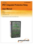
HPB INTEGRATED PROTECTION RELAY 6.6 kV and 22 kV - USER MANUAL Issue: R5 May 2011 CRN: 8575 Ampcontrol User Manual Part No: 117829 Designed and Manufactured in Australia by Ampcontrol CSM Pty Limited. HPB INTEGRATED PROTECTION RELAY USER MANUAL Issue: R5, Date: 6/2011 Safety and other Warnings WARNING! CAUTION! This safety alert symbol identifies important safety messages in this manual and indicates a potential risk of injury or even death to the personnel. When you see this symbol, be alert, your safety is involved, carefully read the message that follows, and inform other operators. This safety alert symbol identifies important information to be read in order to ensure the correct sequence of work and to avoid damage or even destruction of the equipment, and reduce any potential risk of injury or death to the personnel. Supplementary information not directly affecting safety or damage to equipment. Carefully read the message that follows, and inform other relevant personnel. Information concerning possible impact on the environment and actions required for prevention and proper response. HPBB012R5.docx Page 1 HPB INTEGRATED PROTECTION RELAY USER MANUAL Issue: R5, Date: 6/2011 Copyright Notice No part of this publication may be reproduced, transmitted or transcribed into any language by any means without the express written permission of Ampcontrol CSM Pty Ltd, 7 Billbrooke Close, Cameron Park. NSW 2285, Australia. Disclaimer Ampcontrol CSM Pty Ltd will make no warranties as to the contents of this documentation and specifically disclaims any implied warranties or fitness for any particular purpose. Ampcontrol further reserves the right to alter the specification of the system and/or manual without obligation to notify any person or organisation of these changes. Before You Begin We would like to take a moment to thank you for purchasing the HPB Protection Relay. WARNING! To become completely familiar with this equipment and to ensure correct operation, we strongly recommend that you take the time to read and thoroughly understand this user manual. Ampcontrol CSM Contact details: 7 Billbrooke Close, Cameron Park, NSW, 2285 P +61 2 4903 4800 | F +61 2 4903 4888 EMAIL: [email protected] WEB: www.ampcontrolgroup.com HPBB012R5.docx Page 2 HPB INTEGRATED PROTECTION RELAY USER MANUAL Issue: R5, Date: 6/2011 Table of Contents: Safety and other Warnings ............................................................................................................................................ 1 Copyright Notice ............................................................................................................................................................ 2 Disclaimer...................................................................................................................................................................... 2 Before You Begin .......................................................................................................................................................... 2 Ampcontrol CSM Contact details:.................................................................................................................................. 2 1 Receiving and Storage......................................................................................................................................... 5 1.1 Receiving ........................................................................................................................................................ 5 1.2 Storage after Delivery ..................................................................................................................................... 5 1.3 Unpacking of Equipment ................................................................................................................................. 5 2 General safety...................................................................................................................................................... 6 2.1 Personnel Safety Warnings ............................................................................................................................. 6 2.2 Safe Use of Equipment ................................................................................................................................... 6 2.2.1 Changes to Equipment ........................................................................................................................ 6 2.2.2 Equipment Knowledge ........................................................................................................................ 6 2.2.3 Manual Handling ................................................................................................................................. 6 2.2.4 Installation ........................................................................................................................................... 6 2.2.5 Operation ............................................................................................................................................ 6 3 Overview of Equipment ........................................................................................................................................ 7 3.1 Introduction ..................................................................................................................................................... 7 3.2 Remote Display Module (HDM)....................................................................................................................... 7 4 Installation and Wiring Instructions ...................................................................................................................... 9 4.1 Installation ....................................................................................................................................................... 9 4.1.1 Integrated Protection Relay ................................................................................................................. 9 4.1.2 Remote Display Module (HDM) ........................................................................................................... 9 4.1.3 Cable Connection Module ................................................................................................................... 9 4.1.4 Overload & Earth Leakage Toroids ................................................................................................... 10 4.1.5 Toroid Installation Guide Lines .......................................................................................................... 10 4.2 Wiring Installation .......................................................................................................................................... 10 4.2.1 Low Voltage Signals .......................................................................................................................... 11 4.2.2 High Voltage Circuits ......................................................................................................................... 12 4.2.3 Earthing ............................................................................................................................................. 12 5 Machine Communication ................................................................................................................................... 13 5.1 HPB Termination Unit (HTU-1)...................................................................................................................... 13 5.2 Machine Type Codes .................................................................................................................................... 13 5.3 Machine Number ........................................................................................................................................... 13 5.4 Receiver Sensitivity ....................................................................................................................................... 13 6 Earth Protection Functions ................................................................................................................................. 15 6.1 Earth Leakage ............................................................................................................................................... 15 6.2 Earth Fault Lockout ....................................................................................................................................... 15 6.2.1 HPB 6.6kV ......................................................................................................................................... 15 6.2.2 HPB 22 kV ......................................................................................................................................... 15 6.3 Earth Continuity............................................................................................................................................. 16 7 Current Related Functions ................................................................................................................................. 18 7.1 Basic Over-current Protection ....................................................................................................................... 18 7.2 Over-current Characteristic ........................................................................................................................... 18 7.3 Short Circuit .................................................................................................................................................. 19 7.4 Phase Current Balance ................................................................................................................................. 19 8 Voltage Related Functions ................................................................................................................................. 20 8.1 Main Contactor Fail Protection ...................................................................................................................... 20 8.2 Under Voltage Trip ........................................................................................................................................ 20 8.3 Voltage Metering ........................................................................................................................................... 20 HPBB012R5.docx Page 3 HPB INTEGRATED PROTECTION RELAY USER MANUAL Issue: R5, Date: 6/2011 9 User Adjustable Settings .................................................................................................................................... 21 9.1 Parameter Groups......................................................................................................................................... 21 9.1.1 Group 1 Settings ............................................................................................................................... 21 9.1.2 Group 2 Settings ............................................................................................................................... 21 9.2 Changing Settings ......................................................................................................................................... 22 10 System Control .................................................................................................................................................. 23 10.1 Digital Inputs .............................................................................................................................................. 23 10.2 Output Relays ............................................................................................................................................ 23 10.3 Open Collector Outputs ............................................................................................................................. 23 10.4 Outlet Control ............................................................................................................................................. 23 10.5 Operational Sequence ............................................................................................................................... 23 11 Event Log ........................................................................................................................................................... 24 12 Time & Date ....................................................................................................................................................... 26 13 Remote Data Communications .......................................................................................................................... 27 14 HPB Equipment Parts List ................................................................................................................................. 28 15 HPB Specifications ............................................................................................................................................ 29 16 Trouble Shooting................................................................................................................................................ 31 16.1 Pilot Fault Finding Information ................................................................................................................... 33 Appendix A – Drawings ............................................................................................................................................... 35 Appendix B – Approvals .............................................................................................................................................. 49 HPBB012R5.docx Page 4 1 Receiving and Storage HPB INTEGRATED PROTECTION RELAY USER MANUAL Issue: R5, Date: 6/2011 1.1 Receiving All possible precautions are taken to protect the equipment against damage or losses during shipment, however before accepting delivery, check all items against the packing list or Bill of Loading. If there are shortages or evidence of physical damage, notify Ampcontrol immediately. Notify Ampcontrol within 7 days (maximum) in case of shortages or discrepancies, according to the packing list. This action will help ensure a speedy resolution to any perceived problems. Keep a record of all claims and correspondence. Photographs are recommended. Where practicable do not remove protective covers prior to installation unless there are indications of damage. Boxes opened for inspection and inventory should be carefully repacked to ensure protection of the contents or else the parts should be packaged and stored in a safe place. Examine all packing boxes, wrappings and covers for items attached to them, especially if the wrappings are to be discarded. 1.2 Storage after Delivery When the equipment is not to be installed immediately, proper storage is important to ensure protection of equipment and validity of warranty. All equipment should be stored indoors, preferably on shelves (where practicable), and protected from the elements. If storing on the ground use wooden blocks to elevate the equipment above the ground and ensure that the storage area is not an area where water will collect. When applicable correct handling and fork lift procedures must be in place to ensure that any crates and pallets are moved safely. 1.3 Unpacking of Equipment The method of packing used will depend on the size and quantity of the equipment. The following cautions should be interpreted as appropriate. CAUTION! Take care when unpacking crates as the contents may have shifted during transport. Make sure that cable drums are securely attached to their shipping pallets before attempting to move them. The disposal of packaging materials, replaced parts, or components must comply with environmental restrictions without polluting the soil, air or water. Ensure that any timber and cardboard used as packaging is disposed of in a safe and environmentally responsible manner. Where possible, dispose of all waste products i.e. oils, metals, plastic and rubber products by using an approved recycling service centre. HPBB012R5.docx Page 5 HPB INTEGRATED PROTECTION RELAY USER MANUAL Issue: R5, Date: 6/2011 2 General safety 2.1 Personnel Safety Warnings All personnel involved in the installation and operation of this equipment should ensure they are familiar with this manual prior to installing or operating this equipment. WARNING! This equipment generates dangerously high voltage levels. Because of the potential risks associated with this equipment it is essential that only appropriately qualified and experienced personnel be permitted to work on or around this equipment. 2.2 Safe Use of Equipment The equipment supplied has been manufactured according to the state of the art, and designed to ensure a safe operation. The equipment may only be used within the design parameters. The instructions within this manual must be observed as an aid towards achieving maximum safety during operation. The owner/user is responsible for observing the following instructions: 2.2.1 Changes to Equipment Changes in the design and modifications to the equipment are not permitted. 2.2.2 Equipment Knowledge Experience with, or understanding of, this equipment is essential for the safe installation and removal of the equipment. Therefore, in case of a question on how to safely proceed, contact Ampcontrol immediately. 2.2.3 Manual Handling The transformers supplied with the CCMB-22kV are heavy. Care should be taken when transporting and handling these transformers. Precautions have been taken to ensure all equipment is safe to handle and free from sharp edges. However care should always be taken when handling metal enclosures and gloves should be worn. 2.2.4 Installation Correct operation and safety depend on the HPB and associated equipment being installed correctly. Mechanical and or electrical installation and maintenance of plant and equipment must only be carried out by appropriately qualified personnel and must be tested thoroughly prior to operation. 2.2.5 Operation As safety depends on the HPB functioning correctly it is highly recommended that all safety functions of the HPB be periodically tested to ensure correct operation. HPBB012R5.docx Page 6 HPB INTEGRATED PROTECTION RELAY USER MANUAL Issue: R5, Date: 6/2011 3 Overview of Equipment 3.1 Introduction The Ampcontrol HPB Integrated Protection Relay is an intelligent protection relay based on microprocessor technology. The Relay has been specifically designed to operate with very high interference to the pilot conductor that occurs on cables in open cut mining operations. This is more prevalent on a non-symmetric position of the pilot and earth conductors. The integrated relay provides the necessary functions required for protecting electrical outlets supplying draglines, shovels, drills etc. All of the protection functions are combined into a compact, plug-in unit, which can be easily changed out to minimise down time in the event of a problem with the relay. The HPB Relay can provide machine communication through the use of a HPB Termination Unit (HTU-1) connected between the pilot and earth at the machine end of the trailing cable. Through the use of the HTU-1 Termination Unit the relay parameters are automatically up loaded from a remote machine when a cable is inserted into a power outlet. The relay can perform an automatic “H.V. Insulation” test on the cable prior to the closure of the main contactor. The results of the test are displayed on the HPB Display Module (HDM-1) and can be remotely monitored. The HPB Relay has 5 digital inputs, which feed into a microprocessor unit. The microprocessor has been programmed to control three output relays. Relay MCR for the main contactor and Relay CBR for the circuit breaker. RL3 is used to control the supply to the Cable Connection Module enabling it to perform the Earth Fault Lockout test. All of the tripping logic and outlet control is performed by the microprocessor, so that only minimal external control is required. See Typical Connection Diagrams HPBE006 and HPBE013, in Appendix A – Drawings. Extensive information display and monitoring features are included to facilitate fault finding and system trending. This information can be read locally on the HPB Display Module (HDM-1) or remotely via a communication link. Opto isolated outputs are available for connection to optional LED or Relay Modules to provide additional “run” and “trip” indications (See Drawing IPAS005, in Appendix A – Drawings). The Ampcontrol Relay Output Module (ROU) enables these indications to be interfaced with a PLC (See Drawing IPAA031, in Appendix A – Drawings). There are currently two HPB models available; the HPB 6.6kV, which is suitable for 6.6kV systems, and the HPB 22kV, which is suitable for 11kV and 22kV systems. Protection Functions: Earth Leakage Earth Fault Lockout Earth Continuity Over-current/Overload Short Circuit Contactor Fail - Section 6.1 Section 6.2 Section 6.3 Section 7.1 Section 7.3 Section 8.1 Protection trips are stored in a non-volatile memory requiring a reset function before power can be restored. This remains the case even if a power down occurs following a trip condition. 3.2 Remote Display Module (HDM) The Ampcontrol HDM (Remote Display Module) communicates with the HPB Relay via a three-wire connection. The Module consists of a two-line 16 character alpha-numeric liquid crystal display (LCD), LED status indicators and a tactile keypad. The various display pages are arranged on levels with each level having a number of positions. The display level is changed with the Up/Down arrow keys and the Left/Right arrow keys control the display position. An Enter key is used when programming the relay. The display map shows how the movement is controlled between levels and positions (See Drawing HPBB004, in Appendix A – Drawings). HPBB012R5.docx Page 7 HPB INTEGRATED PROTECTION RELAY USER MANUAL Issue: R5, Date: 6/2011 The healthy LED located top centre of the module flashes at 3Hz (three times per second) to indicate healthy communications with the relay. A flash rate of 1Hz (once every second) indicates that the module is powered (15Vd.c.), but not receiving data. The module displays the following information: (a) Software version and serial number. (b) HPB Status. (c) Operational information from the protection functions, e.g. earth leakage current, earth continuity resistance etc. (d) System information including the line voltage and current. (e) Status of digital inputs and relay outputs. (f) Protection trip settings, which can be viewed at any time. Authorised personnel can modify these settings via the HDM Remote Display Module. (g) Data logging information. The 120 most recent events and parameter changes are logged, with time and date, in a non-volatile memory, e.g. (power-up, trip, reset, close etc). A review of the first few log events is a useful tool for fault finding. The HPB Relay status display is one of the most useful features of the relay‟s display system and should be viewed as the first step in fault finding This display shows a list of 9 prompts in order of priority indicating what the HPB Relay requires to allow the outlet to close. The prompts are listed as follows: [RUNNING] Outlet energised [TESTING] Performing EFLO Test [TRIPPED] Trip Condition (see HDM LEDs) [HPB Mem Err] HPB Relays non - volatile memory is corrupted [HTU Mem Err] HTU-1 non - volatile memory is corrupted [HTU STOP] Waiting for HTU-1 stop input to be closed [HPB STOP] Waiting for HPB stop input to open [HPB START?] Waiting for the HPB Relay‟s start input to close [WAITING] Pause between successive Megger Tests An error status indicator is also shown on the status page, which is normally zero; exceptions are as follows: Error # 1 Indicates corruption in the Group 1 Settings (HPB Mem Error). Error # 2 Indicates corruption in the Group 2 Settings (HTU Mem Error). Error # 3 Is a combination of faults in both groups. For details of Groups see Section 9.1, Parameter Groups. HPBB012R5.docx Page 8 HPB INTEGRATED PROTECTION RELAY USER MANUAL Issue: R5, Date: 6/2011 4 Installation and Wiring Instructions This manual has been designed to assist users of the HPB Relay with installation and special wiring techniques required to reduce induction from high voltage circuits. 4.1 Installation 4.1.1 Integrated Protection Relay The HPB Relay has a powder coated sheet steel enclosure designed to be mounted into existing enclosures of adequate IP rating. The relay is designed to operate when mounted either laid down flat or in a vertical position. CAUTION! Vent holes are provided at both the top and bottom of the relay to assist in the cooling of the electronics inside the relay. These vents should not be blocked or restricted in any way. When installing the HPB Relay care should be taken to ensure sufficient space is allowed around the relay for the ease of change out during routine maintenance. Connections to the HPB Relay are made via a plug in base. This base is to be securely fastened to the enclosure in which it is being installed. The base is clearly labelled for ease of terminal location and identification. 4.1.2 Remote Display Module (HDM) The Remote Display Module is housed in an IP55 polycarbonate enclosure. The Module has been designed to be flush mounted, external to the switchgear it is controlling. 4.1.3 Cable Connection Module CCMB - 6.6 kV (6.6kV systems) The CCMB - 6.6 kV (Cable Connection Module type B - 6.6 kV) is a resistive isolation device, which interfaces between the power circuit and the HPB Relay allowing the HPB to measure both the line voltage and the insulation resistance to Earth. A 5 kV d.c. voltage is generated within the CCMB, which under normal operation, applies up to 2.5 kV d.c. between each phase and earth. The CCMB - 6.6 kV is housed in a polycarbonate enclosure. CCMB - 22 kV (11kV and 22kV systems) The CCMB - 22 kV (Cable Connection Module type B - 22 kV) is an isolation device that allows the HPB Relay to interface with the power circuit to measure both the line voltage and the insulation resistance to Earth. The CCMB 22 kV connects to the 11kV or 22 kV power circuit via 3 x voltage transformers connected in a phase to earth configuration with the primary star point connected to Earth through the CCMB - 22 kV. The line voltage is measured on the secondary side of the voltage transformers and an insulation test is performed by lifting the primary star point from earth and applying 5 kV d.c to the star point which passes through the primary windings and is applied to all three phases in parallel. CAUTION! The CCMB and the HPB Relay must be earthed to the same earth connection as the trailing cable on systems with separate earth grids. Ensure that the earth connections are reliably installed, as this is the basis of protection, for the isolation device. HPBB012R5.docx Page 9 HPB INTEGRATED PROTECTION RELAY USER MANUAL Issue: R5, Date: 6/2011 CAUTION! When installing the CCMB – 22 kV, measure the resistance between the transformer primary star point and earth before applying power. Ensure that it is less than 10Ω 4.1.4 Overload & Earth Leakage Toroids Current transformers (CT) are not ideal devices and if correct procedures are not followed during installation, nuisance tripping can result. If using, for example, a single-phase earth leakage system where active and neutral pass through a toroid then at all times currents in the two wires are equal and opposite so that the net current through the toroid is zero. An ideal current transformer would have all the flux from each wire contained in the core and so would accurately add the opposing fluxes to get a net result to zero. A real current transformer has “leakage fluxes”. That is, a very small proportion of the total flux from each cable is not contained in the core, but in the space outside it and as result it may link some turns but not others, depending on the positioning of the cables. The effect of this is that a small output may be obtained from the CT where none would arise if the device was ideal. The size of the error will vary from CT to CT of the same type because of slight differences in the core and the symmetry of the winding. Problems caused in this way become worse as CT sizes increase, as currents increase and a decrease in the symmetry of the cables Nuisance tripping tends to occur when the total current rises, such as when a large motor is started. To help avoid such problems, select the smallest internal diameter CT, which will allow the cables to fit through. 4.1.5 Toroid Installation Guide Lines (a) Keep cables as close to the centre of the toroid as possible. Do not tie them to one side of the toroid. Remember aim at symmetry. (b) Do not bring the cables back past the toroid within one diameter of the CT, trying to cram cables into a small space reduces symmetry and may lead to problems, which are difficult to solve. (c) Avoid placing the CT near any device, which produces magnetic fields, whether it is a transformer or other cables. Try to maintain several CT diameters clearance. (d) Many small cables tend to be worse than for example, three large ones. Try to position the CT in the circuit with this in mind. 4.2 Wiring Installation The connections to the HPB Relay consist of a mix of low and high voltage supplies and relay contact circuits. To reduce induction from high voltages, care needs to be taken in the layout of the wiring and the installation. When using a 110V HPB a power supply filter, e.g. Schaffner FN612-1106 (1A, 250Va.c. chassis mounted filter) or similar, should be installed adjacent to the HPB Relay. The earth should be connected to Pin 7 on the relay as directly as possible. HPBB012R5.docx Page 10 4.2.1 HPB INTEGRATED PROTECTION RELAY USER MANUAL Issue: R5, Date: 6/2011 Low Voltage Signals Care must be taken to ensure these circuits cannot come into contact with higher voltages (e.g. via insulation breakdown, or broken wires etc). It is recommended that these circuits be run in a separate loom from the “high” voltage circuits. To ensure that interference is kept to a minimum, the following cabling is recommended. Duty Pin Signal Recommended Type Pilot Core 6 7 Pilot Earth Single core screened # Screen = 0V Serial Comms Port 8 9 10 11 12 +Vsc FIO TXD RDI OV Four core screened # Screen = 0V 13 14 12 Data +Vdm OV Two core screened # Screen = 0V Earth Leakage Toroid 1 2 EL1 EL2 Two core screened Screen = Earth Cable Connection Module 3 4 5 7 VcmA VcmB VcmC Earth Three core screened Screen = Earth Current Protection Transformers 15 16 17 18 Ia1 Ia2 Ic1 Ic2 Two core screened Screen = Earth Local Stop Button (digital input) 19 20 SpDig+ SpDig- * Two core screened Lock Switch (digital input) 21 22 Lock+ Lock- * Two core screened Reset Switch (digital input) 23 24 Reset+ Reset- * Two core screened Start Switch (digital input) 25 26 Start+ Start- * Two core screened Motor Contactor Aux Contact (digital input) 27 28 MCI+ MCI+ * Two core screened Remote Display Screen = Earth Screen = Earth Screen = Earth Screen = Earth Screen = Earth Low Voltage Signals For explanations of # and * refer to notes following on the next page. HPBB012R5.docx Page 11 HPB INTEGRATED PROTECTION RELAY USER MANUAL Issue: R5, Date: 6/2011 NOTES # The 0V is internally connected to the HPB Relay‟s earth (Pin 7). The screen therefore must NOT be earthed at any other point. * The HPB Relay‟s digital inputs could alternatively be run in a screened multicore cable (Separate cable for each HPB in multiple installations). Where these “low voltage” circuits need to connect near the power circuits (e.g. current transformers, cable connection module, main contactor auxiliaries etc), care needs to be taken to ensure that the circuits are adequately separated and restrained. This ensures that the separation is maintained, even if a wire termination becomes loose etc. 4.2.2 High Voltage Circuits The “high” voltage circuits of the HPB are the 110Va.c. supply (110V version Pins 30, 31 only) and the relay contacts. Apart from keeping these separate from other wiring to the relay, there are no special requirements. CAUTION! 4.2.3 The relay contacts of the HPB Relay must not be used to switch more than 190Va.c., 5A or 100VA. Earthing The HPB has two earth connections. The earth pin 7 is for the communication and pilot circuits. The earth on Pin 29 connects to the earth shield of the HPB Relay‟s internal transformer (110V version only) and chassis. The CCMB-6.6 kV also has an earth connection and the CCMB-22 kV has two earth connections. The CCMB-22 kV signal earth should be connected to the HPB pin 7. All other earth connections should be run back separately to the main earth point. HPBB012R5.docx Page 12 HPB INTEGRATED PROTECTION RELAY USER MANUAL Issue: R5, Date: 6/2011 5 Machine Communication 5.1 HPB Termination Unit (HTU-1) The HTU-1 Remote Termination Unit is a microprocessor based module that is connected between the pilot and earth at the remote end of the trailing cable to provide machine communication. It is powered by and communicates via the pilot line. Its non-volatile memory stores the parameters to configure the outlet as appropriate for that machine (See Drawing HPBM013, in Appendix A – Drawings). The HPB Termination Unit (HTU-1) provides remote stop of the HPB Relay‟s controlled outlet by tripping the Earth Continuity function. The EC LED on the HDM Remote Display Module is illuminated and the Earth Continuity will need to be reset if “Pilot Latch: On” has been selected. Stop switches are connected in series with a diode between the stop and earth terminals. Alternately the internal HTU-1 Termination Module‟s diode can be used to terminate the stop loop. Machine stops can be differentiated from other pilot trips in the HPB Relay‟s Event Log by connecting machine stops into the HTU-I Module‟s “Stop” input instead of being connected in the pilot loop. WARNING! Emergency stops must be wired directly into the pilot circuit. A transient protected internal diode is connected between the diode terminal and earth. When the pilot is connected to the diode terminal the machine can be used with a conventional pilot protection relay such as an Ampcontrol PCA Relay but will NOT operate when connected to an HPB Relay. If the remote stop function is not required the stop terminal must be bridged to the diode terminal or the HPB Relay will not energise. The status of the Remote “Stop” input is displayed “HTU: Online Run” or “HTU: Online Stp” and can be viewed on the HDM Module‟s “Pilot and HTU Information” page (Level 2, Position 1). Also displayed on this page is Off Line Status and pilot information. The HTU-1 software version and machine type is displayed on Position 2. The Remote termination settings are programmed via the HDM Remote Display Module (Section 9, User Adjustable Settings). 5.2 Machine Type Codes There are 5 selectable machine type codes available for use in the HTU-1 Termination Unit. The descriptive code is transmitted to the HPB Relay to identify the type of machine connected to the outlet. The codes are selected using the HDM Remote Display Module (Level 9, Position 1). DrgL - Drag Line Shvl - Shovel Dril - Drill PSTx - Portable Transformer Wpmp - Water Pump 5.3 Machine Number Machine numbers 1 to 40 can be assigned to machines (1 to 40 for each machine type). These numbers are programmed using the HDM Remote Display Module (Level 9, Position 2). 5.4 Receiver Sensitivity The HPB allows the sensitivity of the HTU receiver to be adjusted to suit different installations. For installations HPBB012R5.docx Page 13 HPB INTEGRATED PROTECTION RELAY USER MANUAL Issue: R5, Date: 6/2011 where multiple HPBs are located close to each other the sensitivity can be reduced to prevent crosstalk between the pilot signals. In installations with long trailing cables the sensitivity can be increased. The sensitivity can be adjusted from 1 – 32, with larger values corresponding to decreased sensitivity. For most installations starting with the sensitivity set to 8 should yield good results. If the HTU is connected through a long trailing cable and the HTU is not coming online, try increasing the sensitivity. Alternatively, if there are multiple relays installed near each other, and they do not behave as expected try decreasing the sensitivity to prevent crosstalk. HPBB012R5.docx Page 14 6 Earth Protection Functions HPB INTEGRATED PROTECTION RELAY USER MANUAL Issue: R5, Date: 6/2011 6.1 Earth Leakage The earth leakage protection function uses a toroid to measure the earth leakage current. A definite time operating characteristic is provided with an adjustable trip sensitivity and time delay. When a fault occurs and the trip level and time delay are exceeded; a trip occurs. The trip acts in the Main Contactor Relay (MCR) logic and is latched. An earth leakage trip is treated as a special fault and requires an authorised person to perform the reset function. This is achieved by holding the lock input closed and then closing the reset button. When an earth leakage trip occurs, the “EL” LED on the display module flashes and the open collector output on the HPB Relay is switched on to provide additional monitoring if required. The measured instantaneous leakage current (EL) is displayed on the HDM “Earth Fault Information” page as a percentage of the trip level. When the leakage reaches 100% for the selected time delay a trip occurs. For the HPB 6.6kV the trip level is adjustable in 100mA increments over the range 200mA-1000mA and for the HPB 22 kV the trip level is selectable in 250mA increments over the range 500mA-2500mA. The time delay is selectable as instantaneous (<80mS) or adjustable in 40mS increments over the range of 150mS-470mS. 6.2 Earth Fault Lockout 6.2.1 HPB 6.6kV On 6.6 kV systems the earth fault lockout function tests the resistance of the 3 phase lines to earth by applying a “megger test” prior to closing the main contactor. The test is initiated by closing the start input (provided all other starting conditions are met (see Section 10.5, Operational Sequence). The HPB Relay closes its relay output, RL3, which applies 110Va.c. to the CCMB-6.6 kV (Cable Connecting Module type B - 6.6 kV). This is a resistive isolation device used to interface the HPB Relay to the power conductors. A 5 kV d.c. voltage is generated within the CCMB6.6 kV, which under normal operation applies up to 2.5 kV d.c. between each phase and earth. The HPB Relay measures the voltage on the line and calculates the meg-ohm resistance to earth of each phase. At the end of the test, provided the value is above the preset threshold, the MCR relay closes allowing the outlet to be energised. If the value is below the preset threshold, an Earth Fault Trip occurs. At the completion of a test, the resistance to earth of each phase is retained in memory until the next test is carried out. This can be viewed on the HDM (Remote Display Module) (Level 3, Position 2). 6.2.2 HPB 22 kV On 11 kV and 22 kV systems the earth fault lockout function tests the resistance of the 3 phase lines to earth by applying a “megger test” prior to closing the main contactor. The test is initiated by closing the start input (provided all other starting conditions are met (see Section 10.5, Operational Sequence). The HPB Relay closes its relay output, RL3, which applies 48Vd.c. to the CCMB-22 kV (Cable Connecting Module type B - 22 kV). The CCMB-22 kV then disconnects the primary windings of its 3 x voltage transformers from earth (they are connected to earth at all other times), and generates 5 kV d.c. which is applied to the primary star point, resulting in 5 kV d.c between all three phases and earth. The HPB Relay then measures the current to earth and calculates the resistance of the line insulation to earth of all three phases in parallel. Three seconds (3 s) after the end of the test, if the calculated resistance is above the preset threshold, the MCR relay closes allowing the outlet to be energised. If the calculated resistance is below the preset threshold, an Earth Fault Trip occurs. At the completion of a test, the result is retained in memory until the next test is carried out. This can be viewed on the HDM (Remote Display Module) (Level 3, Position 2). An insulation test will yield one of the following results: (a) "Hardware Fault" - The HPB cannot detect the presence of the CCMB. Check power supply to the CCMB and all wiring (Note: An open circuit connection between the CCMB and power circuit cannot be detected and will not display as "Hardware Fault"). (b) "< 10 MΩ" - The resistance between the power circuit and earth is less than 10 MΩ. (c) A value between 10 MΩ and 120 MΩ - The resistance between the power circuit and earth ± 10%. (d) "> 120 MΩ" - The resistance between the power circuit and earth is greater than 120 MΩ. HPBB012R5.docx Page 15 HPB INTEGRATED PROTECTION RELAY USER MANUAL Issue: R5, Date: 6/2011 WARNING! The CCMB generates 5kVd.c. This high voltage d.c. is produced, and applied to the 3 phase lines, even when the high voltage 3 phase supply is not available. Care should therefore always be taken when working close to high voltage 3 phase cables/bus etc. An audible tone is generated whenever the CCMB is active, warning of the presence of high voltage d.c. CAUTION! Like all insulation tests, a faulty (open circuit) connection to the power circuit will create the appearance of a high insulation resistance to earth. To verify the connection to the power circuit it is recommended that periodic insulation tests be performed, using the HPB, with a known resistance (e.g. 50 MΩ) or a short circuit to earth on the line. This should be done on an isolated system (high voltage supply disconnected) using control power only. The start input must be held closed for the duration of the test (including the 3 s delay on HPB 22 kV) which is adjustable between 10 and 25 seconds to allow for the charging of cable capacitance. Setting the “EFLR Test” value to “off” disables the Earth Fault test. If this is done, and the system is ready to start, the MCR Relay closes as soon as the start input is closed. 6.3 Earth Continuity The earth continuity function tests for the continuity of the earthing between the outlet and the machine, via the pilot core in the trailing cable. The pilot core is also used to transfer machine data when a remote HTU (HPB Termination Unit) is used to achieve machine communication. The pilot resistance is measured with a d.c. signal and communication is achieved by a high frequency a.c. signal. The HPB Relay can be configured to operate in either Resistor or HTU Mode. The mode is selected in “Pilot Type”, (Level 8, Position 1) and defines the type of termination unit to be connected between the pilot and earth at the machine end of the trailing cable being protected by the HPB Relay. The advantage of using the resistor mode is that it uses a simple signal and a robust termination device making the system easy to fault find. The disadvantages are: (a) An incorrect healthy Earth Continuity indication could be produced by a pilot that has faulted to earth with a resistance within the pickup range of the HPB Relay. For example if the selected trip level is 50, then the fault to earth in the range of 200 to 285 would be seen as a healthy circuit. (b) The “Machine Communication” functions of the HPB Relay are not available. The advantages of using HTU mode are: (a) Machine communication. (b) Machine stops can be differentiated from Earth Continuity Trips in the HPB Event Log. (c) Increased security in pilot system as the HPB Relay must receive an intelligent signal from the HTU-1 Termination Module in order to deem the pilot circuit healthy. The net disadvantage is that the increased complexity in the system may make trouble shooting difficult. Resistor Mode When the pilot is set to “Res” Mode the trailing cable pilot is terminated with a 235 resistor to earth (2 x 470 , 5 Watt resistors connected in parallel). The HPB Relay measures the resistance of the pilot - earth loop and HPBB012R5.docx Page 16 HPB INTEGRATED PROTECTION RELAY USER MANUAL Issue: R5, Date: 6/2011 assumes that the pilot circuit is healthy if the resistance measured is between 235 and 235 + RTrip (the selected trip resistance). If the resistance measured is below 200 a short circuit fault between the pilot and earth conductors is assumed and a trip occurs, which in turn de-energises the MCR Relay. In “Res” mode all of the relay settings are stored in the HPB Relay. If a load is moved to a different outlet (or substation) then the HPB Relay‟s settings need to be checked and updated if necessary. HTU Mode When the pilot is set to “HTU” Mode the trailing cable pilot is terminated with a HTU-1 Termination Module. The HPB Relay measures the resistance of the pilot - earth loop and assumes that the pilot circuit is healthy if the resistance measured is below the selected trip resistance level. If the resistance exceeds the preset level a trip will occur. The Event Log will display “EC Trip”. In “HTU” mode the relay settings that pertain to the actual load connected are stored in the HTU-1 Termination Module, which is installed in the machine. If a machine cable is moved to a different outlet (or substation) then the protection settings for the machine are automatically uploaded to the HPB Relay. The earth continuity resistance (ECR) of the pilot – earth loop is displayed in ohms on the HDM “Earth Fault Information” page (level 3, position 1). The leakage (SC) between the pilot and earth conductors is displayed as OK or Trp. The Event Log will display “EC Short” if a short occurs between pilot and earth when the outlet is energised. The Earth Continuity (EC) Trip resistance for both modes is selectable to 50, 75, and 100 ohms. Pilot Trip Time is adjustable to allow for operation in noisy electrical environments. The following trip times are available: 300 ms, 400 ms, 500 ms, 600 ms, 800 ms, 1.0 s, 1.2 s, 1.5 s and 2 s. A maximum setting of 600 ms should be suitable for most installations. CAUTION! Long time delays should only be used where necessary. Consequences of long trip times should be thoroughly assessed from a safety point of view before using the higher values. When an Earth Continuity trip occurs the HPB Relay de-energises the MCR Relay. The “EC” LED on the display module is illuminated and the open collector output on the relay is switched on to provide remote monitoring if required. The Earth Continuity can be set to be latching or non-latching (See Section 9, User Adjustable Settings). This allows the user to determine if the fault is manually or automatically reset once the pilot - earth loop is healthy. The selection is either “Pilot Latch: On” or “Pilot Latch: Off”. For Pilot Fault Finding information; see Section 16.1. HPBB012R5.docx Page 17 7 Current Related Functions HPB INTEGRATED PROTECTION RELAY USER MANUAL Issue: R5, Date: 6/2011 7.1 Basic Over-current Protection Two current transformers are used to measure the three line currents. The measured currents are used to implement the following protection functions: (a) (b) (c) Over-current Short Circuit Phase Current Balance Full load settings cover a range from 7.5 Amps to 464 Amps for the HPB 6.6kV and 15 Amps to 928 Amps for the HPB 22kV. A current range and current multiplier are utilised to select and store the full load current value in the non-volatile memory. This forms the basic reference level for the over-current protection functions. The current range is selectable in 4 Amp increments between 60 and 116 Amps. The current multiplier is selectable at 1/8, 1/4, 1/2, 1, 2, 4 times for the HPB 6.6kV and at 1/4, 1/2, 1, 2, 4, 8 times for the HPB 22kV. The selected Range and Multiplier combine to give the basic level. Example: To obtain a full load current of 152 Amps select a current range of 76 Amps and a multiplier of 2. Two curve types can be selected. A selected time multiplier modifies the basic trip time characteristic. This multiplier is selected from 0.05 times to 1.0 times. The instantaneous current in each of the three phases can be displayed on the display module (Level 5, Position 1). The display is expressed as a percentage of the selected full load current and reads between 0 and 999% (i.e. up to 9.99 times full load current). When the load current exceeds the full load current level, a trip accumulator is incremented at a rate dependant on the current. When this accumulator reaches 100%, an over-current trip occurs. The trip accumulator can be viewed on the HDM Remote Display Module (Level 5, Position 2). This may be useful to determine how close an outlet gets to trip condition during start up. If the accumulator reaches almost 100% as the load gets away then this may indicate that the over-current settings are too low. Conversely, if the trip accumulator only builds up slightly on a heavy start, then the over-current settings may be set too high. If an over-current trip occurs, the “OC” LED flashes, and the “OC” open collector output switches on to provide remote monitoring if required. Following an over-current trip, the following conditions must be met to affect a reset: (a) The trip accumulator must be less than 80% (b) The HPB Relay‟s reset input must be closed 7.2 Over-current Characteristic The current-time trip characteristics can be selected as either Very Inverse, or Extremely Inverse, corresponding to the “OC Type” values of "vInv" or “xInv”. The drawings, Very Inverse Over-current Curves, HPBB003, in Appendix A – Drawings and Extremely Inverse Over-current Curves, HPBB001, in Appendix A – Drawings, show the trip characteristics. HPBB012R5.docx Page 18 HPB INTEGRATED PROTECTION RELAY USER MANUAL Issue: R5, Date: 6/2011 7.3 Short Circuit The short circuit function has a definite time characteristic. If the current exceeds the selected level for the pre-set time then a trip occurs. When a trip occurs, the "SC" LED on the display module flashes and the open collector output on the HPB Relay is switched on to provide monitoring if required. To reset the relay following a short circuit trip it is necessary to hold the lock input closed and then close the reset button. The HPB Relay can be programmed so that a short circuit trip will operate either the "CBR" relay or the "MCR” Relay. This can be achieved by selecting the required relay at the "SC Relay" selection in the non-volatile memory (See Section 9, User Adjustable Settings). Normally the “CBR” selection would be used. If “MCR” is selected then the user must ensure that the interrupting device that is operated by the MCR Relay has sufficient current interrupting capacity at the system voltage for the situation in which it is installed. The short circuit trip level is adjustable from 3 to 10 times (full load current) in 0.5 increments. The trip time is selectable from 40 to 160mS. 7.4 Phase Current Balance Phase current balance protection is selected via the “Cur Bal Trp” selection (See Section 9, User Adjustable Settings). The current balance measurement is displayed on the Remote Display Module and is calculated as: Ibal = MAX I x 100% Iave = Average of the 3 phase currents Where: Iave MAX I = The maximum deviation of a phase current from the average The trip level is selectable at 5%, 10%, 20%, 50% and off. The phase current balance protection is inhibited until the average current exceeds both 20% of the selected full load current and the selected balance trip level. If the trip level is exceeded, a timer is triggered. If the imbalance remains above the set level for more than two seconds the relay trips. The event log records “Ibal” to differentiate it from a true over-current trip. The status of the timer is displayed adjacent to the “Ibal” value (Level 5, Position 2) on the HDM Remote Display Module. A trip condition occurs when the timer reaches 100%. HPBB012R5.docx Page 19 8 Voltage Related Functions HPB INTEGRATED PROTECTION RELAY USER MANUAL Issue: R5, Date: 6/2011 8.1 Main Contactor Fail Protection The Main Contactor Fail (MCF) protection operates if the Main Contactor fails to function by: (a) Failing to open when required. This is achieved by comparing the state of the main contactor (via the Main Contactor Input MCI) against the state of the MCR Relay output. This provides a “Pilot Fail Timer” function. (b) Failing to maintain insulation across the contacts when the contactor is open. The Cable Connection Module is used to measure the voltage on the load side of the contactor. If this exceeds 10% of the rated line voltage, a trip will occur. This function is inhibited immediately after the main contactor opens or a cable test is performed to allow for the cable capacitance to discharge. The back EMF inhibit time is adjustable from 2 to 40 seconds (See Section 9, User Adjustable Settings). A main contactor fail trip causes the CBR Relay to de-energise, which trips the circuit breaker. An internal battery backed indication flag in the HPB Relay is also tripped. A LED on the front panel of the HPB Relay begins to flash. The “MCF” LED on the Remote Display Module flashes and the open collector output on the HPB is switched on to provide remote monitoring if required. To reset the flag, access to the relay is necessary. The reset button is accessible through the front fascia of the relay and must be pressed for 1 second. 8.2 Under Voltage Trip Under voltage protection is enabled as soon as the main contactor is closed (indicated by closing the MCI input). If any of the phase voltages drop below the selected trip setting of the nominal line voltage for 800ms then the outlet is stopped. This is recorded in the event log as “uVOLT Trp”. The trip level is selectable from 30% to 80% in 10% increments or can be set to “Off” (Level 8, Position 6) on the HDM Remote Display Module. The “Off” selection disables the under voltage trip function and is usually used for non 6.6 kV installations. 8.3 Voltage Metering The Cable Connection Module (CCMB), in addition to enabling the Earth Fault test, is used to provide line voltage metering. The outgoing line voltages for each of the 3 phases are displayed as a % of the nominal line voltage on the HDM Remote Display module (Level 4, Position 1). The maximum reading is 140% for the 6.6 kV systems and 120% for the 11 kV and 22 kV systems. HPBB012R5.docx Page 20 9 User Adjustable Settings HPB INTEGRATED PROTECTION RELAY USER MANUAL Issue: R5, Date: 6/2011 9.1 Parameter Groups The HPB Relay has many user adjustable settings, which are stored in non-volatile memory. These can be viewed and modified via the HDM Remote Display Module. The settings are split into two groups as outlined below. The first group of parameters relates to settings, which are linked to the power system rather than the particular load connected to the outlet. These are always stored in the HPB Relay. 9.1.1 Group 1 Settings Pilot Mode: Determines if the pilot is to be terminated with a Resistor or a HTU-1 Termination Unit EL Sens: Sets the sensitivity for the Earth Leakage protection trip EL Time: Sets the trip time for the Earth Leakage protection EFLR Test: Sets the Earth Fault lockout level Eft time: Selects the test time for the Earth Fault lockout test to allow for line capacitance U/V Trip: Selects the under voltage trip threshold as a % of line volts SC Relay: Selects which HPB output relay is tripped in event of a short circuit trip HTU rx Lev: Adjusts the sensitivity of HTU data receiver The second group of settings consists of parameters that are related to the load connected to the protected outlet. These settings are stored, retrieved to/from the memory in the HPB Relay or the memory in the HTU-1 Termination Unit, depending on the “Pilot Mode” setting. If the Resistor Pilot Mode is selected the HPB Relay reads and writes to and from the relay‟s internal memory for the group 2 settings. If the HTU Pilot Mode is selected the settings are sent to and retrieved from the memory in the Remote Termination Unit. 9.1.2 Group 2 Settings HTU MC Type: Allows the HTU-1 to transmit a descriptive code to identify the machine connected to the outlet HTU MC No: Allows the HTU-1 to transmit an assigned machine number OC I range: Sets the basic current range OC I mul: Combines with OC range to define the full load current OC Type: Selects either very inverse or extremely inverse over-current curves OC t mul: Modifies the basic over-current time curves to achieve the desired trip times Cur Bal Trp: Adjusts the current phase balance trip level SC I trip: Sets the short circuit trip level SC Trip t: Sets the trip time for the short circuit function Pilot Latch: Determines whether earth continuity trips are self resetting or not B-emf TIME: Adjustable time delay to inhibit main contactor fail routine following opening of main contactor Remote Start: No function this version HPBB012R5.docx Page 21 9.2 Changing Settings HPB INTEGRATED PROTECTION RELAY USER MANUAL Issue: R5, Date: 6/2011 The procedure for adjusting the settings is independent of where the values are stored. (a) Ensure the outlet is stopped. (b) For Group 2 Settings in HTU Mode, ensure the HTU-1 Termination Unit is on line. (c) Display the parameter that has to be changed on the HDM Remote Display Module's liquid crystal display (Level 8 or 9). (d) (e) Momentarily operate the lock input. A warning message appears. Press the enter button to acknowledge the warning message and to confirm that a change is desired. (f) Use the left and right arrows to step through the allowable values until the desired new setting is displayed. (g) Press the enter button to indicate that the value shown is the required new setting. (h) Momentarily operate the lock input. The display will show a confirming message, then return to the viewing level. If the up or down keys are operated during the procedure the HPB Relay aborts the modifying sequence. When changes have been made to the stored values, the old value and the new value are stored in the event log. A separate log immediately proceeds this recording the time and date that the change was made. When the relay has been selected for HTU Mode the HTU Remote Termination Unit must be on line (shown at level 2, position 1 on the HDM) before Group 2 settings can be adjusted. HPBB012R5.docx Page 22 System Control 10 HPB INTEGRATED PROTECTION RELAY USER MANUAL Issue: R5, Date: 6/2011 10.1 Digital Inputs The HPB Relay has five digital inputs, which are all voltage free contact inputs. Shorting the two input terminals together activates them. The inputs are MCI, start, stop, lock and reset. The status of inputs can be displayed on the HDM Remote Display Module (Level 6, Positions 2-3). The “Lnk” input shown in the display is used in tests by Ampcontrol Engineers. 10.2 Output Relays The HPB Relay has output relays to control the main contactor and the circuit breaker (under voltage control). All relays are fail safe with respect to power supply loss and are controlled on the basis of protection functions. Relay RL3 operates to initiate the cable fault lockout test. There is one spare relay reserved for future development. The status of the relays can be displayed on the HDM Remote Display Module (Level 6, Position 1). 10.3 Open Collector Outputs The HPB Relay has eight open collector outputs, which are driven through opto couplers to provide additional indication if required. These can be used to drive LED‟s, or additional relays (with appropriate drive circuitry). The Ampcontrol Relay Output Module (ROU) enables these indications to be interfaced with a PLC (See Drawing IPAA031, in Appendix A – Drawings). The eight outputs correspond to the LED‟s on the display module, turning on whenever the corresponding LED is flashing. The signals are available on the HPB Relay‟s base, pins 35-42, and the common is on pin 34. 10.4 Outlet Control Closing the Start input energises the outlet. Both the remote and local stop buttons will turn off the outlet. If a remote stop is not required the Stop input must be bridged to earth via a diode at the HTU-1 Termination Module. 10.5 Operational Sequence Before an outlet can be energised the following conditions must apply: (a) (b) No protection faults present Local stop input open, remote stop loop closed (c) Local start input closed Once these conditions are obtained a cable fault lock out test is performed automatically. The start button must remain closed during the test, which may take up to 25 seconds to complete due to the charging of the cable capacitance. If the result of this test is satisfactory the HPB Relay goes into the run mode and the MCR Relay picks up. The "RUN" LED on the HDM Remote Display Module is illuminated and the open collector output on the HPB Relay is switched on to provide remote monitoring if required. A time delay of 5 seconds is allowed for the Main Contactor Interlock (MCI) to close. If it does not close within this time, then the run mode is exited. If a stop button is operated while the relay is in run mode, the run is cleared, and the MCR Relay de-energises. The event log reads "Stopped" or “HTU Stop” depending on which stop button caused the stop condition. If a stop button is operated during a cable fault lockout test, then the test is aborted. While the main contactor is closed, the MCI input is continuously monitored. If it opens, the run is cleared and the MCR relay de-energises. In this case the event log records "MC Opened" which indicates that the outlet was turned off by something other than the HPB Relay, e.g. open circuited main contactor coil or control supply. HPBB012R5.docx Page 23 11 Event Log HPB INTEGRATED PROTECTION RELAY USER MANUAL Issue: R5, Date: 6/2011 A real time clock/calendar is included in the HPB Relay. This combines with the non-volatile memory to provide data logging. This log sequentially records the time, date and details of the HPB Relay‟s operations. A chronological list of the previous 120 events is stored. The event log can be scrolled so as to view the entire log. To achieve this press “Enter” followed by the “right or left” arrow keys to commence the scroll. The log will scroll one log per second in the direction of the arrow key pressed. Press “Enter” to stop the scroll at the desired log. A typical display shows: LOG 10: EL TRIP MO 15/05 09:46:21 This record shows that an earth leakage caused a trip condition on Monday, 15 May at 9.46am. Log 10 indicates that it is the 10th log in the list. Log 1 is always the most recent event. Each time a new log is recorded, the 120th log is removed from the list and all others move along one. The following events are logged: "Power Up" Records the time when the HPB Relay is powered up "Pwr Down" Records the time when the HPB Relay loses power "MCR Close" Closure of the Main Contactor Relay "Stopped" Stopping of the outlet by operation of the local stop button "HTU Stop" Stopping of the outlet by operation of the remote stop button "MC Opened" Main Contactor has opened but not initiated by the HPB Relay "EC Trip" Pilot/Earth continuity loop exceeds the trip level “EC Short” Low resistance between pilot and earth "EL Trip" Earth leakage protection tripped "EF trip A" Earth Fault test has failed - A phase (HPB 6.6kV). "EF trip B" Earth Fault test has failed - B phase (HPB 6.6kV). "EF trip C" Earth Fault test has failed - C phase (HPB 6.6kV). “EF trip” Earth Fault test has failed – (HPB-22 kV) "SC Trip" Trip condition of short circuit protection "OC Trip" Trip condition of over-current overload protection "I bal-Trp" Current balance trip condition "RESET" Records resetting of a protection trip "Setup Mod" Records that setup data has been modified. The log preceding this shows the old and new values. "uVOLT Trp" Records that voltage was not present on at least one outgoing phase when the main contactor was closed "MCF F Trp" Internal battery backed main contactor fail flag tripped “MCF-V trp” Main Contactor Fail trip due to sensing voltage on the load side of the main contactor when the contactor should be open. “MCI Fail” Main Contactor Input (MCI) shows the main contactor to be closed HPBB012R5.docx Page 24 HPB INTEGRATED PROTECTION RELAY USER MANUAL Issue: R5, Date: 6/2011 when it should be open. “-P reset” Internal microprocessor reset "Mem.ERROR" Records that the relay's non-volatile parameter memory has been corrupted "HTU mem.E" Records that the remote termination unit‟s non volatile memory has been corrupted or remote termination unit has gone off line while the outlet is running. HPBB012R5.docx Page 25 Time & Date 12 HPB INTEGRATED PROTECTION RELAY USER MANUAL Issue: R5, Date: 6/2011 If there is a need to adjust the real time clock, carry out the following procedure: (a) Using the Remote Display Module select the time and date information page (Level 7, Position 1) to display the Day, Month, Year, Hours and Minutes. - - - - - - - - - - - - MO 150595 09:46 (b) Press the enter key. A “v” will appear in the top line above the minute section. This indicates the number to be changed. (c) Use the left and right arrow keys to move the “v” to the desired position. (d) Press the enter key. The “v” now changes to a “?” The right arrow key is used to increment the allowable values, once the desired value is obtained, press the enter key again. The “?” returns to a “v”. Repeat steps (c) and (d) until the correct time and date is displayed. (e) (f) (g) With the “v” showing press the lock push button. The “v” then changes to “E” (This is a prompt to press the enter key). Press the enter key. At that instant, the seconds are zeroed and the selected time/date information is transferred to the internal clock. If the battery voltage is low the time will zero and the date will reset to 1st January on power up. If the battery is flat or faulty the relay is likely to trip on “main contactor fail” on power up. HPBB012R5.docx Page 26 13 Remote Data Communications HPB INTEGRATED PROTECTION RELAY USER MANUAL Issue: R5, Date: 6/2011 The HPB Integrated Protection Relay protection relay has the facility for connecting remote monitoring equipment. This can be in the form of either the Remote Display Module or other peripheral equipment such as PLC‟s. For PLC applications the Ampcontrol DNET-IP2 Serial Communication System transfers data and commands between the Host System and the modules using RS232, RS422 and RS485 protocols. Each integrated protection relay is connected to a Serial Interface (IPSI), which has its output drop connected to a DNET-IP2 Protocol Converter. The Protocol Converter provides the communications link to a PLC (See User Manual 118626 for further details). HPBB012R5.docx Page 27 14 HPB Equipment Parts List HPB INTEGRATED PROTECTION RELAY USER MANUAL Issue: R5, Date: 6/2011 144069 - HPB 6.6 kV Integrated Protection Relay 142842 - HPB 22 kV Integrated Protection Relay 118732 - HTU-1 Termination Unit 142848 - HPB Base 142845 - HPB Base – 48V 118542 - HDM Remote Display Module Flush Mount 117648 - 6.6 kV Cable Connection Module 143369 - 22 kV Cable Connection Kit 144371 - 11 kV Cable Connection Kit 101503 - IPA/IPB Relay/LED Output Module 117829 - HPB User Manual 143911 - 48Vd.c, 120W Power Supply HPBB012R5.docx Page 28 15 HPB INTEGRATED PROTECTION RELAY USER MANUAL Issue: R5, Date: 6/2011 HPB Specifications Note: An 11kV system includes the HPB 22kV relay. Auxiliary Supply Volts: HPB 6.6kV - 110Vac ± 20%, >20VA, 50Hz ± 2 Hz HPB 22 kV - 48Vd.c. ± 20%, > 40 W Recommended Power Supply: Meanwell – DR- 120 Ampcontrol Part No. 143911 Earth Leakage Protection: HPB 6.6kV - Trip Setting 200 mA to 1000mA in 100 mA increments HPB 22 kV - Trip Setting 500 mA to 2500mA in 250 mA increments Time Delay: Instantaneous, <80ms and 150ms to 470ms (in 40 ms increments). Earth Continuity Protection: Trip Setting 50 , 75, and 100 Shunt Leakage Trip if < 200 (Resistor Mode) Operating Time 300 ms, 400 ms, 500 ms, 1.0 s, 1.2 s, 1.5 s and 2 s Earth Fault Lockout Protection: Lockout Resistance: Test Time: HPB 6.6kV - Selectable at 2, 5, 10, 20 and 50 Meg Ohm and off HPB 22 kV - Selectable at 15, 20, 30, 50 and 100 Meg Ohm and off Selectable at 10, 15, 20 and 25 seconds Over-current Protection: Current Range: Current Multiplier: Time Multiplier: HPB 6.6kV - 7.5 to 464 Amps (60 to 116 Amps in 4 Amp increments, times current multiplier) HPB 22kV - 15 to 928 Amps (60 to 116 Amps in 4 Amp increments, times current multiplier) HPB 6.6kV - 1/8, 1/4, 1/2, 1, 2, 4 times HPB 22kV - 1/4, 1/2, 1, 2, 4, 8 times 0.05, 0.075, 0.1, 0.15, 0.2, 0.3, 0.4, 0.5, 0.6, 0.7, 0.8, 1.0 times Current Balance: Trip Settings: 5%, 10%, 20%, 50% and OFF Short Circuit Protection: Trip Setting: Trip Time (ms): 3.0 to 10.0 times in 0.5 increments (times full load current) 40, 60, 80, 100, 120, 160 Back EMF Timer: Trip Delay Settings: HPBB012R5.docx 2, 5, 10, 15, 20, 25, 30, 35, 40 seconds Page 29 Machine Numbers: HPB INTEGRATED PROTECTION RELAY USER MANUAL Issue: R5, Date: 6/2011 Can be allocated from 1 to 40 Under Voltage Protection: Selectable from 30% to 80% in 10% increments, or disabled. Trip delay 800ms Serial Communication Port: For information on data format and hardware see DNET-IP2 Serial Communication System User Manual 118626 Relay Contacts: MCR, CBR 1 N/0 5A/190 Va.c. 100 VA maximum 1 C/0 5A/190 Va.c. 100 VA maximum RL3 1 N/0 5A/190Va.c. 100 VA maximum 22 kV Transformers: Rated Voltage: 22 kV, 50Hz Insulation: 24 / 50 / 125 kV Voltage Factor: 1.9 / 30 sec Ratio: 22 kV / √3 to 110 / √3 Class: 0.2 VA Rating: 10 VA Standard: AS60044.2 N terminal capable of withstanding 5kV d.c. test voltage. 11 kV Transformers: Rated Voltage: 11 kV, 50Hz Insulation: 12 / 28 / 75 kV Voltage Factor: 1.9 / 30 sec Ratio: 11 kV / √3 to 110 / √3 Class: 0.2 VA Rating: 10 VA Standard: AS60044.2 N terminal capable of withstanding 5kV d.c. test voltage. Transformers must be able to withstand 5 kV d.c. on the primary side. HPBB012R5.docx Page 30 16 HPB INTEGRATED PROTECTION RELAY USER MANUAL Issue: R5, Date: 6/2011 Trouble Shooting If a problem is experienced with the relay use the following table to fault find the problem. Should the fault persist, remove the relay and return the relay plus a description of the fault to Ampcontrol for repairs. The HBP has no user serviceable parts. All repairs must be carried out by Ampcontrol personnel only. If a fault develops return the HBP to Ampcontrol for repair. It is essential that no attempt be made to repair the HBP as any attempt to dismantle or repair the HBP can seriously compromise the safety of the unit and the consequence can be fatal. WARNING! The Status page (level 0, position 1) should be the first step in troubleshooting. This displays what the relay requires to make it operate. Also check the first six event logs. Symptom Cause Remedy Loss of power to the Display. Check there is power to the relay and it is correctly plugged in. Relay supplies 15Vd.c. to the HDM. Check cable between HDM and the relay. Faulty Display Module. Replace module. Remote Display shows a blank screen. The HDM Led flashes at 1 Hz. Power to HDM is healthy but there is no data Check data cable between the relay and the HDM. Error Indication #1(level 0, Position 1). Corruption in the Group 1 Settings, stored in the relay. Examine the Group 1 Settings (level 8) to check the stored parameters in the non-volatile memory. One or several settings will show „???‟. Re-program lost settings into the memory. Error Indication #2 (level 0, Position 1) when in HTU pilot mode Either the HTU-1 Module is not on line or the HTU-1 Module‟s non volatile memory has been corrupted Check that the HTU-1 Module is on line (level 3, position 1) ie., a healthy pilot loop. If the HTU-1 Module is on line examine the Group 2 Settings stored in the HTU Settings (level 9). One or several other settings will show „???‟. Reprogram lost settings into the HTU-1 memory. Error Indication #3 (level 0, position 1). Combination of faults causing errors #1 and #2. As outlined above for Errors #1 and #2. Relay will not close. EC fault indicated. Faulty pilot circuit (open or high resistance or shorted to earth) Check pilot circuit. (See detailed fault finding information, page 15) If still faulty replace the relay. HPB Status page displays: [HTU Stop] Relay is waiting for the HTU-1 Module‟s Stop input to be closed. Ensure HTU-1 Module‟s stop input is closed (through a diode to earth). Outlet is off and the log records “MC Opened”. Outlet was turned off but not by the relay. Check main contactor coil or control circuit. Remote Display shows a blank screen. The HDM LED indicator located on the top of the HDM module is off. HPBB012R5.docx Page 31 HPB INTEGRATED PROTECTION RELAY USER MANUAL Issue: R5, Date: 6/2011 Symptom Cause Remedy The relay‟s MCI input is not closing (level 6 position 2). Check that main contactor is closing. If not check circuit. Check auxiliary contacts and wiring. Check system voltage display (level 4, position 1) as contactor closes. Compare this with the under voltage threshold. Relay will not remain closed and cycles while the start input is held closed. Relay not receiving voltage feedback on all three outlet phases within 800mS of contactor closing. Check continuity from the relay, through the CCMB - 6.6 kV to power conductors. WARNING! Be sure to follow the appropriate high voltage isolation procedures. HPB 6.6kV Typical reading: CCMB - 6.6K 27 Meg Ohm Main contactor fail condition. Check main contactor for leakage across terminals on frozen contactor condition. Flat or faulty battery. AA cell installed under the top cover requires replacement. The owner in a workshop environment can replace a direct replacement battery. It is recommended that the relay be returned to Ampcontrol for battery replacement and full testing. Time and date incorrect. Resets to 1/01/9? on power up. Low battery. AA cell installed under the top cover requires replacement. The owner in a workshop environment can replace a direct replacement battery. It is recommended that the relay be returned to Ampcontrol for battery replacement and full testing. HDM Displays “Hardware fault”. CCMB has not been detected. Check all wiring to the CCMB and earthing. Relay Trips on MCF on power up. HPBB012R5.docx Page 32 HPB INTEGRATED PROTECTION RELAY USER MANUAL Issue: R5, Date: 6/2011 16.1 Pilot Fault Finding Information To carry out tests on a faulty earth continuity circuit adopt the following procedures: Open circuit pilot Check the voltage between the pilot and earth at the HPB Relay (Pins 6 and 7). The reading should be 30Vd.c. To determine the location of the fault continue the above test along the pilot until no reading is obtained. Current check Connect a d.c. ammeter between the pilot and earth at the HPB Relay (Pins 6 and 7). The reading should be 45 mA at the HPB Relay or at any point along a continuous pilot. Repeat this test at the machine end of the pilot. If the voltage is normal (30V d.c.) but the current is less than 45mA then the loop resistance may be too high. Tests in Resistor Mode When Resistor Mode has been selected the pilot is terminated with a 235 resistor. The voltage measured across the resistor should be 10.6V d.c. The voltage measured at the HPB Relay will vary depending on the amount of resistance in the pilot earth loop. For example if the loop resistance is 100 then the voltage at the HPB Relay will increase by 4.5 volts (100 x 0.045) resulting in a reading of 15.1 V d.c.. Tests in HTU Mode When HTU Mode has been selected the pilot is terminated with an HTU-1 Termination Module. The voltage measured across the Pilot and Earth terminals of the module should be approximately 20V d.c.. The voltage measured at the HPB Relay will vary depending on the amount of resistance in the pilot earth loop. For example if the loop resistance is 100 then the voltage at the HPB Relay will increase by 4.5 volts (100 x 0.045) resulting in a reading of 24.5 V d.c.. HPBB012R5.docx Page 33 HPB INTEGRATED PROTECTION RELAY USER MANUAL Issue: R5, Date: 6/2011 HPBB012R5.docx Page 34 Appendix A – Drawings HPB INTEGRATED PROTECTION RELAY USER MANUAL Issue: R5, Date: 6/2011 Drawing Number Description HPBE006 Typical Connection Diagram – HPB 6.6 kV HPBE013 Typical Connection Diagram – HPB 22 kV HPBE012 Typical Connection Diagram – CCMB 22 kV HPBB004 HPB Display Map HPBB003 Very Inverse Over-current & Short Circuit Curves HPBB001 Extremely Inverse Over-current & Short Circuit Curves IPBB003 Adjustable Setting Storage HPBM005 HPB Enclosure Dimensions HPBM013 HPB HTU-1 Termination Unit HPBM015 Enclosure Details - Remote Display Module HDM HPBM030 HPB Base Connections HPBM029 HPB 48 V Base Connections HPBM001 CCMB 6.6 kV Cable Connection Module – Overall & Mounting Dimensions HPBA018 CCMB 22 kV Cable Connection Module – Overall & Mounting Dimensions IPAS005 IPA/IPB Relay/LED Output Module IPAA031 Relay Output Module – General Arrangement The drawings appear in the following pages in the same order in which they are listed in the table above. HPBB012R5.docx Page 35 Appendix B – Approvals HPBB012R5.docx HPB INTEGRATED RELAY USER MANUAL Issue: R3, Date: 09/2010. CRN: 8060 Page 49 HPB INTEGRATED RELAY USER MANUAL Issue: R3, Date: 09/2010. CRN: 8060 HPBB012R5.docx Page 50 HPB INTEGRATED RELAY USER MANUAL Issue: R3, Date: 09/2010. CRN: 8060 HPBB012R5.docx Page 51