1
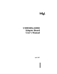
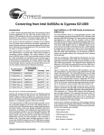
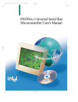
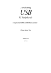
Keil Software, Inc.
Application Note
Solving RISM, USB, and dScope Communication Problems
APNT_110
OVERVIEW
This application note discusses how to solve the problems you may encounter when you interface
the Keil dScope debugger to the Intel USB Evaluation Board using RISM. Typically, these
problems are not software related. They are related to proper configuration or connection of the
serial ports.
This application note does not discuss how to create programs for the evaluation board. For more
information on creating USB programs, refer to Keil Application Note 109.
CONFIGURING THE USB EVALUATION BOARD
The USB evaluation board from Intel includes an 8x930Ax microcontroller with built-in USB
protocol circuitry. This board must be properly configured before anything else will work. Make
sure you configure the board exactly as specified in the 8xC93x Eval Board Users’ Guide and in
the 8X930xx Adapter Board User’s Guide.
CONNECTING YOUR PC TO THE USB EVALUATION BOARD
Interfacing to RISM running on the USB evaluation board should be fairly straight-forward. The
following sections explain the various features and caveats you should take into consideration.
CHOOSING A SERIAL PORT
There are two serial ports on the USB evaluation board. One is driven by the external UART.
The other is driven by the on-chip UART.
The external 16550 UART uses the serial port connector at J2 to
connect to your PC. This is the same chip used in the PC for
serial communications and it should work well with any PC. We
recommend using the external UART for the following reasons.
External UART
Parameter
Specification
Baud Rate
19,200
Serial Jack
J2
Label
UART
n When you debug using the external UART, the on-chip
UART of the 8x930Ax is available for your target program. You may need the on-chip
UART to interface a serial device to USB.
n The baud rate of the external UART depends on the programmed divisor and the clock rate of
an external oscillator. It does not change when the 8x930Ax goes into power-down mode.
The on-chip UART uses the serial port connector at J1 to
connect to your PC. Your target application may not use the
on-chip UART when you debug using RISM. We do not
recommend using the on-chip UART for debugging.
On-Chip UART
Parameter
Specification
Baud Rate
9,600
Serial Jack
J1
Label
n RISM can only use the on-chip UART at 9600 baud.
Downloading software takes longer due to the slower baud rate.
Page 1 of 6
SERIAL I/O
Revision date: 23-Feb-97
Keil Software, Inc.
Application Note
Solving RISM, USB, and dScope Communication Problems
APNT_110
n Timer2 is used as the baud rate generator and is not available for your target programs.
n The baud rate of the on-chip UART changes when the 8x930Ax goes into power-down. This
will probably change in future revisions of the chip, but for now it plays serious havoc with the
debugger.
VERIFYING SERIAL PORT OPERATION
You may use a terminal program with your PC to verify proper connection with the USB
evaluation board. The following steps show what to do.
1. Connect a COM port from your PC to the appropriate serial port connector on the USB board.
2. Start your terminal program and set the serial port parameters to one of the following:
n External UART: 19,200 baud, 8-bits, 1 stop bit, no parity.
n On-Chip UART: 9,600 baud, 8-bits, 1 stop bit, no parity.
3. Apply power to the USB evaluation board. The LEDs on the board should cycle P1.0, P1.1,
P1.2 and so on. You should end up with P1.0, P1.2, P1.4, P1.6, and P1.7 illuminated. If all
LEDs are illuminated, something is holding the board in RESET. RISM uses DTR to start
and stop running a program. You may need to enable hardware handshaking in your terminal
program to the let the board run.
4. As you type characters in your terminal program, you should see the LEDs on the USB
evaluation board change to reflect the ASCII value. You should also see the next character
echoed to your terminal. For example, if you type 1, you will see 2 echoed.
TROUBLESHOOTING THE SERIAL PORT
After following the above steps, you should be able to communicate with the USB evaluation
board. If not, the following suggestions may help.
n Make sure you have selected the correct COM port.
n Make sure that the UARCT DIP switch is on if you use the external UART on the USB
evaluation board. This switch must be off to use the on-chip UART.
n Check to see if the COM port you selected is shared with an internal modem. Remember that
COM ports and internal modems may not share interrupts.
n Make sure the serial cable is good. You should use a 9-pin male to 9-pin female that is wired
straight through pin-to-pin.
n Laptop users should make sure to disable power-down features of the serial ports. If
power-down is enabled and if you don’t use the serial port for a while, your laptop may power
the COM ports down and you may lose your connection with the USB evaluation board.
Page 2 of 6
Revision date: 23-Feb-97
Keil Software, Inc.
Application Note
Solving RISM, USB, and dScope Communication Problems
APNT_110
n Since the RISM communications protocol does not include a checksum or CRC byte, the
connection between the USB board and the PC must be error-free. Any line glitches will cause
problems (and will probably be interpreted as RISM commands).
INTERFACING TO RISM USING DSCOPE
Once you have verified proper connection between your PC and the USB evaluation board, you are
ready to use the dScope debugger. When dScope is invoked, the following screen appears.
Register Window
Debug Window
Command Window
LOADING A CPU DRIVER
dScope performs simulation and target debugging by using CPU driver DLLs to provide complete
support for each different type of CPU. For example, the 80251S.DLL provides simulation
support for the Intel 8x251Sx devices. The 82930.DLL provides simulation support for the Intel
82930 device. RISM251.DLL and RISM930.DLL provide target debugging support for hardware
using the RISM251 and RISM930 monitor programs.
Using the drop-down box in the main menu, select RISM930.DLL for the RISM
monitor on the USB evaluation board. If the RISM930.DLL driver does not appear
in your menu, you may select the RISM251.DLL driver. These two drivers are
virtually identical. Alternatively, you may download the latest software from the
Keil web site at http://www.keil.com/usb or you may contact technical support at 800-648-0251
and request the latest drivers.
Page 3 of 6
Revision date: 23-Feb-97
Keil Software, Inc.
Application Note
Solving RISM, USB, and dScope Communication Problems
APNT_110
After successfully loading the RISM CPU driver and negotiating with the USB evaluation board,
the Command Window appears as follows.
THE PERIPHERALS MENU
When dScope successfully loads the RISM CPU driver, the Peripherals menu is
added to the main dScope menu. This menu gives you access to dialog boxes that
display many of the on-chip peripherals including the I/O ports, the Interrupt SFRs,
the timer/counters, and the serial port. In addition, dialogs are available that display
CPU parameters programmed in the configuration bytes and that let you edit the configuration
information used by dScope to communicate with RISM.
Configuration Dialog Box
The Configuration dialog box lets you change the parameters used
to communicate with RISM. Unless special circumstances exist,
you should leave these parameters set as shown. The Port will be
the COM port to use to communicate with RISM. The Baudrate
will be 19,200 if you use the USB evaluation board external
UART and 9,600 if you use the USB evaluation board on-chip
UART. When selected, Enable serial break lets you halt a
program that is running using the stop button.
CPU Parameters Dialog Box
The MCS 251 Parameters dialog box shows you settings in the
configuration bytes of the 8x930Ax. Binary mode indicates
that the 8x930Ax decodes opcodes for 251 binary mode.
Source mode indicates that the 8x930Ax decodes opcodes for
251 source mode. Framesize-2 indicates that 2 bytes are saved
on the stack when an interrupt occurs (low 2 bytes of the
program counter). Framesize-4 indicates that 4 bytes are saved (24 bits of the program counter
and PSW1). Refer to the 8X930Ax Universal Serial Bus Microcontroller User’s Manual for more
information about source and binary mode and interrupt frame sizes.
Page 4 of 6
Revision date: 23-Feb-97
Keil Software, Inc.
Application Note
Solving RISM, USB, and dScope Communication Problems
APNT_110
Parallel Ports
dScope makes it easy to view the I/O ports of the 8x930Ax using the
Parallel Ports dialog box. Using this dialog box, you can see the state of
each bit in each port.
NOTE
You cannot change the port bits from this dialog. You may, however,
change them from the Command Window.
VERIFYING THE DSCOPE TO RISM INTERFACE
The following example shows you a simple way to confirm that dScope and RISM are
communicating.
You can display and alter the contents of memory on the USB evaluation board using dScope’s
Command Window. Select the Command Window using the mouse and enter the following:
P1
P1=0x81
The Command Window should appear as follows:
And, the LEDs on the USB evaluation board will change so that only P1.7 and P1.0 are
illuminated.
WHAT TO DO IF IT DOESN’T WORK
There are very few things to break when you interface to your target using the dScope debugger.
Most problems are caused by communication failures at the outset. When dScope cannot initially
communicate with the target system, the following dialog box appears.
Make certain that the correct COM port and baudrate are specified and click Try Again.
Page 5 of 6
Revision date: 23-Feb-97
Keil Software, Inc.
Application Note
Solving RISM, USB, and dScope Communication Problems
APNT_110
Refer to “Verifying Serial Port Operation” above for a more in depth discussion of how to test the
PC to USB board interface. Many of the problems should be ironed out manually before
attempting to use the dScope debugger.
Note that no errors should be generated when dScope successfully initializes the USB evaluation
board using RISM. If you consistently get either of the following error messages, there is a
problem communicating with RISM.
*** Serial I/O: time out
*** Serial transmission failed (Req=4, Act=0)
Since there have been several iterations of RISM and several iterations of our interface DLLs,
make sure you have the latest version of our tools. You may download the latest software from the
Keil web site at http://www.keil.com/usb or you may contact technical support at 800-648-0251
and request the latest drivers.
CONCLUSION
There are a number of considerations when connecting the USB evaluation board to your PC’s
COM ports. Most problems are due to improper RS-232 port configuration, incorrect port
selection and speed, conflicting PC interrupts, and laptop power-down circuitry. It is our opinion
that RS-232 will continue to be the most trouble-shot interface in the world. That is, until USB
replaces the COM port on the PC.
Copyright © 1997 Keil Software, Inc. All rights reserved.
In the USA:
Keil Software, Inc.
16990 Dallas Parkway, Suite 120
Dallas, TX 75248-1903
USA
In Europe:
Keil Elektronik GmbH
Bretonischer Ring 15
D-85630 Grasbrunn b. Munchen
Germany
Sales:
Phone:
FAX:
800-348-8051
972-735-8052
972-735-8055
Phone:
FAX:
(49) (089) 45 60 40 - 0
(49) (089) 46 81 62
E-mail:
[email protected]
[email protected]
E-mail:
[email protected]
[email protected]
Page 6 of 6
Internet: http://www.keil.com/
Revision date: 23-Feb-97