1
V2400 Series Expansion Modules User
Manual
Fifth Edition, November 2012
www.moxa.com/product
© 2012 Moxa Inc. All rights reserved.
V2400 Series Expansion Modules User
Manual
The software described in this manual is furnished under a license agreement and may be used only in accordance with
the terms of that agreement.
Copyright Notice
© 2012 Moxa Inc., All rights reserved.
Trademarks
The MOXA logo is a registered trademark of Moxa Inc.
All other trademarks or registered marks in this manual belong to their respective manufacturers.
Disclaimer
Information in this document is subject to change without notice and does not represent a commitment on the part of
Moxa.
Moxa provides this document as is, without warranty of any kind, either expressed or implied, including, but not limited
to, its particular purpose. Moxa reserves the right to make improvements and/or changes to this manual, or to the
products and/or the programs described in this manual, at any time.
Information provided in this manual is intended to be accurate and reliable. However, Moxa assumes no responsibility for
its use, or for any infringements on the rights of third parties that may result from its use.
This product might include unintentional technical or typographical errors. Changes are periodically made to the
information herein to correct such errors, and these changes are incorporated into new editions of the publication.
Technical Support Contact Information
www.moxa.com/support
Moxa Americas
Moxa China (Shanghai office)
Toll-free: 1-888-669-2872
Toll-free: 800-820-5036
Tel:
+1-714-528-6777
Tel:
+86-21-5258-9955
Fax:
+1-714-528-6778
Fax:
+86-21-5258-5505
Moxa Europe
Moxa Asia-Pacific
Tel:
+49-89-3 70 03 99-0
Tel:
+886-2-8919-1230
Fax:
+49-89-3 70 03 99-99
Fax:
+886-2-8919-1231
Table of Contents
1.
Introduction ...................................................................................................................................... 1-1
Overview ........................................................................................................................................... 1-2
Package Checklist ............................................................................................................................... 1-2
Available Modules ............................................................................................................................... 1-2
EPM-3338 Optional Accessories ..................................................................................................... 1-2
EPM Module Specifications ................................................................................................................... 1-2
EPM-3032 Specifications .............................................................................................................. 1-2
EPM-3112 Specifications .............................................................................................................. 1-3
EPM-3337 Specifications .............................................................................................................. 1-3
EPM-3438 Specifications .............................................................................................................. 1-5
EPM-3552 Specifications .............................................................................................................. 1-5
EPM-DK01 Specifications .............................................................................................................. 1-5
EPM-DK02 Specifications .............................................................................................................. 1-6
EPM-DK03 Specifications .............................................................................................................. 1-6
EPM-3338 Specifications .............................................................................................................. 1-7
2.
Hardware Introduction...................................................................................................................... 2-1
Appearance........................................................................................................................................ 2-2
EPM-3032................................................................................................................................... 2-2
EPM-3112................................................................................................................................... 2-2
EPM-3337................................................................................................................................... 2-2
EPM-3438................................................................................................................................... 2-2
EPM-3552................................................................................................................................... 2-3
EPM-DK01 .................................................................................................................................. 2-3
EPM-DK02 .................................................................................................................................. 2-4
EPM-3338................................................................................................................................... 2-4
EPM-DK03 .................................................................................................................................. 2-5
Dimensions ........................................................................................................................................ 2-6
3.
Hardware Connection Description ..................................................................................................... 3-1
Installing the EPM Expansion Modules ................................................................................................... 3-2
Connecting Data Transmission Cables ................................................................................................... 3-2
EPM-3032 Serial Port Module ........................................................................................................ 3-2
EPM-3337 Wireless/GPS Module .................................................................................................... 3-3
EPM-3438 DI/DO Module .............................................................................................................. 3-3
EPM-3112 CAN Bus Module........................................................................................................... 3-4
EPM-DK01 Module: mini PCI + mini PCIe Sockets ............................................................................ 3-4
EPM-3552 Display Module............................................................................................................. 3-4
EPM-DK02 Module: 2 mini PCIe Sockets ......................................................................................... 3-6
Installing Cellular/Wi-Fi Modules on the EPM-DK02, EPM-DK03, or EPM-3338 ............................................. 3-6
Configuring Power Controls on Socket 1 ......................................................................................... 3-6
Installing a Cellular Module ........................................................................................................... 3-7
Arranging Cables on the Wi-Fi or Cellular Modules ......................................................................... 3-10
4.
Software Installation and Programming Guide ................................................................................. 4-1
Linux System Peripherals Programming Guide ........................................................................................ 4-2
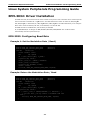
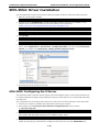
EPM-3032: Driver Installation............................................................................................................... 4-2
EPM-3032: Configuring Baud Rate ................................................................................................. 4-2
EPM-3032: Configuring Serial Port Modes ....................................................................................... 4-3
EPM-3438: Driver Installation............................................................................................................... 4-5
EPM-3438: Programming Digital I/O or the Counter ......................................................................... 4-6
Implementing Timer Functions on Digital IO Ports ........................................................................... 4-9
EPM-3337 Driver Installation .............................................................................................................. 4-15
EPM-3337: Operating Modes ....................................................................................................... 4-16
EPM-3337: Setting up a Wi-Fi Connection..................................................................................... 4-21
EPM-3337: Getting Wireless Card Information............................................................................... 4-23
EPM-3112: CAN Bus Interface ............................................................................................................ 4-23
EPM-3112: Driver Installation ..................................................................................................... 4-23
EPM-3112: Programming Guide .................................................................................................. 4-24
EPM-3552: Driver Installation............................................................................................................. 4-26
EPM-3552: Configuring the X Server ............................................................................................ 4-26
EPM-3552: Enabling a Dual Screen Display ................................................................................... 4-27
EPM-3552: Configuring a Single Display ....................................................................................... 4-28
EPM-3552: Dynamically Changing the Display Resolution ............................................................... 4-28
EPM-DK02: Driver Installation ............................................................................................................ 4-29
EPM-DK02: Installing the Kernel Module....................................................................................... 4-29
EPM-DK02: Configuring Power Controls ........................................................................................ 4-29
EPM-DK03: Driver Installation ............................................................................................................ 4-31
EPM-DK03: Installing the GPS Test Clients ................................................................................... 4-31
EPM-3338: Driver Installation............................................................................................................. 4-32
EPM-3338: Wi-Fi Module ............................................................................................................ 4-32
EPM-3338: Cellular Module ......................................................................................................... 4-33
EPM-3338: GPS Module .............................................................................................................. 4-34
Windows System .............................................................................................................................. 4-36
EPM-3032: Driver Installation............................................................................................................. 4-36
EPM-3032: Configuring Serial Port Mode ...................................................................................... 4-38
EPM-3032: Changing the Software-Selectable UART Mode .............................................................. 4-40
EPM-3438: Driver Installation............................................................................................................. 4-41
EPM-3438: Programming Guide .................................................................................................. 4-43
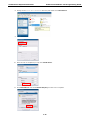
EPM-3337: Driver Installation............................................................................................................. 4-44
EPM-3338: Wireless Module Driver Installation.............................................................................. 4-48
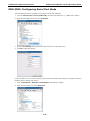
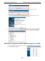
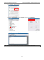
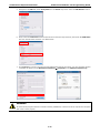
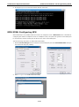
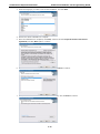
EPM-3338: Configuring a GPRS/HSDPA Connection (no GPS) .......................................................... 4-50
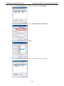
EPM-3338: Configuring GPS........................................................................................................ 4-53
EPM-3338: Configuring a Wi-Fi/802.11 Connection ........................................................................ 4-54
EPM-3112: Driver Installation............................................................................................................. 4-57
EPM-3112: Programming Guide .................................................................................................. 4-58
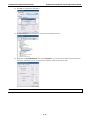
EPM-3552: Driver Installation............................................................................................................. 4-60
EPM-3552: Patch File Installation ................................................................................................ 4-62
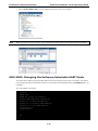
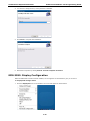
EPM-3552: Display Configuration ................................................................................................ 4-63
EPM-3552: Configuring Extended Dual Displays ............................................................................ 4-64
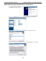
EPM-DK02: Driver Installation ............................................................................................................ 4-66
EPM-DK02: Controlling Power ..................................................................................................... 4-68
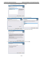
EPM-DK03: Driver Installation ............................................................................................................ 4-69
EPM-DK03: GPS Driver Installation .............................................................................................. 4-69
EPM-DK03: Cellular Driver Installation ......................................................................................... 4-73
EPM-DK03: Wi-Fi Driver Installation ............................................................................................ 4-74
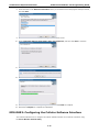
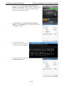
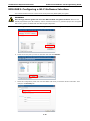
EPM-DK03: Configuring the Cellular Software Interface .................................................................. 4-76
EPM-DK03: Configuring a Wi-Fi Software Interface ........................................................................ 4-78
EPM-DK03: Getting Wi-Fi Information .......................................................................................... 4-80
A.
Video Performance Table for the EPM-3552 Module .......................................................................... A-1
EPM-3552 Display Module Performance on Linux Systems........................................................................ A-2
EPM-3552 Display Module Performance on Windows Systems ................................................................... A-3
1
1.
Introduction
Moxa’s EPM series modules, which include modules with serial ports, a wireless/GPS card, a digital input/output
channel card, a CAN bus card, a mini PCI/PCIe card, a VGA/DVI-I display card, and a 2-slot mini PCIe card,
work with Moxa’s V2422 and V2426 embedded computers, giving end-users the ability to set up and expand a
variety of industrial applications.
The following topics are covered in this chapter:
Overview
Package Checklist
Available Modules
EPM-3338 Optional Accessories
EPM Module Specifications
EPM-3032 Specifications
EPM-3112 Specifications
EPM-3337 Specifications
EPM-3438 Specifications
EPM-3552 Specifications
EPM-DK01 Specifications
EPM-DK02 Specifications
EPM-DK03 Specifications
EPM-3338 Specifications
V2400 Series Expansion Modules
Introduction
Overview
Moxa’s EPM series modules provide expansion options for V2422 and V2426 embedded computers. Modules
may provide serial ports, combined Wi-Fi/GPS, a digital I/O channels, CAN bus interface, mini PCI/PCIe
interfaces, combined VGA/DVI-I display, and a 2-slot mini PCIe card, giving end-users the ability to set up
V2400 computers for a wide variety of industrial applications.
Package Checklist
Each package ships with a single EPM expansion module and a quick installation guide
NOTE: Please notify your sales representative if the module is damaged en route.
Available Modules
•
EPM-3032: 2 isolated RS-232/422/485 ports, DB9 connectors
•
EPM-3112: 2 isolated CAN ports with DB9 connectors
•
EPM-3337: HSDPA, GPS, Wi-Fi (11a/b/g/n)
•
EPM-3338: GPS, HSPA, Wi-Fi (802.11a/b/g/n)
•
EPM-3438: 8+8 DI/DO, with 3 KV digital isolation protection, 2 KHz counter
•
EPM-3552: VGA or DVI-I display module
•
EPM-DK02: 2-slot Mini PCIe expansion module
•
EPM-DK03: GPS + 2-slot Mini PCIe expansion module
EPM-3338 Optional Accessories
Wi-Fi Module
•
Sparklan WPEA-121N 802.11 a/b/g/n Wi-Fi module
•
WPEA-121N extender
•
Antenna jack with RF cable (x2)
Cellular (HSPA) Module
•
Sierra Wireless MC8305 HSPA card
•
Thermal pad
•
Antenna jack with cable
EPM Module Specifications
EPM-3032 Specifications
Serial Interface
Serial Standards: 2 RS-232/422/485 ports, software-selectable (DB9 male)
Isolation: 2 KV digital isolation
Serial Communication Parameters
Data Bits: 5, 6, 7, 8
Stop Bits: 1, 1.5, 2
Parity: None, Even, Odd, Space, Mark
Flow Control: RTS/CTS, XON/XOFF, ADDC® (automatic data direction control) for RS-485
Baudrate: 50 bps to 921.6 Kbps (non-standard baudrates supported; see user's manual for details)
Serial Signals
1-2
V2400 Series Expansion Modules
Introduction
RS-232: TxD, RxD, DTR, DSR, RTS, CTS, DCD, GND
RS-422: TxD+, TxD-, RxD+, RxD-, GND
RS-485-4w: TxD+, TxD-, RxD+, RxD-, GND
RS-485-2w: Data+, Data-, GND
Physical Characteristics
Weight: 137 g
Dimensions: 104 x 121 x 34 mm (4.09 x 4.76 x 1.34 in)
Environmental Limits
Operating Temperature: -40 to 70°C (-40 to 158°F)
EPM-3112 Specifications
CAN bus Communication
Interface: 2 optically isolated CAN2.0A/2.0B compliant ports
CAN Controller: Phillips SJA1000T
Signals: CAN-H, CAN-L
Isolation: 2 KV digital isolation
Speed: 1 Mbps
Connector Type: DB9 male
Physical Characteristics
Weight: 127 g
Dimensions: 104 x 121 x 34 mm (4.09 x 4.76 x 1.34 in)
Environmental Limits
Operating Temperature: -25 to 55°C (-13 to 131°F)
EPM-3337 Specifications
Cellular Interface
Frequency Bands:
• UMTS/HSDPA: Triple band, 850/1900/1900 MHz
• GSM/GPRS/EDGE: Quad band, 850/900/1800/2100 MHz
• GSM Dass: Small MS
Output Power:
• Class 4 (2 W) for GSM850/900
• Class 3 (0.25 W) for UMTS/HSDPA
• Class E2 (0.5 W) for EDGE850/900
• Class E2 (0.4 W) for EDGE1800/1900
• Class 1 (1 W) for GSM1800/1900
HSDPA Interface
3GPP Release 5:
• 3.6 Mbps, UL 384 Kbps
• UE CAT. [1-6], 11, 12 supported
• Compressed mode (CM) supported according to 3GPP TS25.212
GPS Interface
Tracking: Tracks up to 13 satellites, L1 1575.42 MHz
Accuracy Position: 2.5 m CEP; 5.0 m SEP
Protocols: NMEA-0183 V2.3, E911 AGPS Control plane, GPS dedicated AT commands, Date WGS-84
Tracking sensitivity: -158 dBm (with active antenna)
Start-up Time:
• Hot start: <3s
• Cold start: 30s
• Warm start: 30s
GPS active antenna supply: 3.3 V
1-3
V2400 Series Expansion Modules
Introduction
WLAN Interface
Supported Modes:
• IEEE 802.11a/b/g/n for client/bridge mode
• IEEE 802.11b/g/n for AP mode (Linux OS only)
Standards:
• IEEE 802.11a/b/g/n for Wireless LAN
• IEEE 802.11i for Wireless Security
Operating Channels (central frequency):
• US: 2.412 to 2.462 GHz (11 channels), 5.18 to 5.24 GHz (4 channels)
• EU: 2.412 to 2.472 GHz (13 channels), 5.18 to 5.24 GHz (4 channels)
• USA: 1 to 11 (2400 to 2483.5 MHz)
• Europe: 1 to 13 (2400 to 2483.5 MHz)
• Japan: 1 to 14 (2400 to 2497 MHz)
802.11g:
• USA: 1 to 11 (2400 to 2483.5 MHz)
• Europe: 1 to 13 (2400 to 2483.5 MHz)
• Japan: 1 to 13 (2400 to 2497 MHz)
802.11a:
• USA: 36 to 165 (5180 to 5825 MHZ)
• Europe: 36 140 (5180 to 5700 MHz)
• Japan: 7 to 11 (5035 to 5055MHz),183 to 189 (4915 to 4945 MHz)
Security: 64-bit and 128-bit WEP encryption, WPA /WPA2-Personal and Enterprise (IEEE 802.1X/RADIUS,
TKIP and AES)
Transmission Rates:
• 802.11b: 1, 2, 5.5, 11 Mbps
• 802.11a/g: 6, 9, 12, 18, 24, 36, 48, 54 Mbps
• 802.11n: 6 to 300 Mbps (multiple rates supported)
TX Transmit Power:
• 802.11b: 1 to 11 Mbps: Typ. 18 dBm (± 1.5 dBm)
• 802.11g: 6 to 24 Mbps: Typ. 18 dBm (± 1.5 dBm); 36 to 48 Mbps: Typ. 17 dBm (± 1.5 dBm); 54 Mbps: Typ.
15 dBm (± 1.5 dBm)
• 802.11a: 6 to 24 Mbps: Typ. 17 dBm (± 1.5 dBm) 36 to 48 Mbps: Typ. 16 dBm (± 1.5 dBm); 54 Mbps: Typ.
14 dBm (± 1.5 dBm)
TX Transmit Power MIMO:
• 802.11a/n (20/40 MHz): MCS15 20 MHz: Typ. 13 dBm (± 1.5 dBm); MCS15 40 MHz: Typ. 12 dBm (± 1.5
dBm)
• 802.11g/n (20/40 MHz): MCS15 20 MHz: Typ. 14 dBm (± 1.5 dBm); MCS15 40 MHz: Typ. 13 dBm (± -1.5
dBm)
RX Sensitivity:
• 802.11b:
-92 dBm @ 1 Mbps, -90 dBm @ 2 Mbps, -88 dBm @ 5.5 Mbps, -84 dBm @ 11 Mbps
• 802.11g:
-87 dBm @ 6 Mbps, -86 dBm @ 9 Mbps, -85 dBm @ 12 Mbps, -82 dBm @ 18 Mbps, -80 dBm @ 24 Mbps, -76
dBm @ 36 Mbps, -72 dBm @ 48 Mbps, -70 dBm @ 54 Mbps
• 802.11a:
-87 dBm @ 6 Mbps, -86 dBm @ 9 Mbps, -85 dBm @ 12 Mbps, -82 dBm @ 18 Mbps,
-80 dBm @ 24 Mbps, -76 dBm @ 36 Mbps, -72 dBm @ 48 Mbps, -70 dBm @ 54 Mbps
RX Sensitivity MIMO:
• 802.11a/n:
-68 dBm @ MCS15 40 MHz, -70 dBm @ MCS7 40 MHz, -69 dBm @ MCS15 20 MHz, -71 dBm @ MCS7 20 MHz
• 802.11g/n:
-68 dBm @ MCS15 40 MHz, -70 dBm @ MCS7 40 MHz, -69 dBm @ MCS15 20 MHz,
-71 dBm @ MCS7 20 MHz
1-4
V2400 Series Expansion Modules
Introduction
AP-only Protocols: ARP, BOOTP, DHCP, dynamic VLAN-Tags for 802.1X-Clients, STP/RSTP (IEEE 802.1D/w)
Default Antenna: 2 dBi dual-band omni-directional antenna, RP-SMA (male)
Connector for External Antennas: RP-SMA (female)
Physical Characteristics
Weight: 220 g
Dimensions: 104 x 121 x 34 mm (4.09 x 4.76 x 1.34 in)
Environmental Limits
Operating Temperature: -25 to 55°C (-13 to 131°F), EN 50155 Class T1
EPM-3438 Specifications
Digital Input
Input Channels: 8, source type
Input Voltage: 0 to 30 VDC at 25 Hz
Digital Input Levels for Dry Contacts:
• Logic level 0: Close to GND
• Logic level 1: Open
Digital Input Levels for Wet Contacts:
• Logic level 0: +3 V max.
• Logic level 1: +10 V to +30 V (Source to DI)
Counter Frequency: 2 KHz (DI0 only)
Connector Type: 10-pin screw terminal block (8 DI points, DI Source, GND)
Isolation: 3 KV optical isolation
Digital Output
Output Channels: 8, sink type, 0 to 30 VDC
Output Current: Max. 200 mA per channel
On-state Voltage: 24 VDC nominal, open collector to 30 VDC
Connector Type: 9-pin screw terminal block (8 DO points, GND)
Isolation: 3 KV optical isolation
Physical Characteristics
Weight: 120 g
Dimensions: 104 x 121 x 34 mm (4.09 x 4.76 x 1.34 in)
Environmental Limits
Operating Temperature: -40 to 70°C (-40 to 158°F), EN 50155 Class TX
EPM-3552 Specifications
Display
Graphics Controller: DsiplayLink DL-195
VGA Interface: 15-pin D-sub connector (female)
DVI Interface: 24-pin DVI-I connector (female)
Resolution: Up to 1920x 1600 (2048 x 1152 for wide screen) resolution
Physical Characteristics
Weight: 130 g
Dimensions: 104 x 121 x 34 mm (4.09 x 4.76 x 1.34 in)
Environmental Limits
Operating Temperature: -25 to 55°C (-13 to 131°F)
EPM-DK01 Specifications
PCI Express Mini Slot
Interface: PCIExpress V1.0 (one lane)
1-5
V2400 Series Expansion Modules
Introduction
USB 2.0 Bus SIM Card Holder: Reserved for Cellular applications
Mini PCI Slot
Interface: PCI
Bus Frequency: 32-bit, 33 MHz PCI
Physical Characteristics
Weight: 117 g
Environmental Limits
Operating Temperature: -40 to 70°C
(-40 to 158°F), EN 50155 Class TX
EPM-DK02 Specifications
PCI Express Mini Slot
Interface:
Slot 1: PCIExpress V1.0 (one lane) / USB 2.0
Slot 2: USB 2.0
USB 2.0 Bus SIM Card Holder: Reserved for cellular applications
Physical Characteristics
Weight: 125 g
Environmental Limits
Operating Temperature: -25 to 55°C
(-13 to 131°F), EN 50155 Class T1
EPM-DK03 Specifications
PCI Express Mini Slot
Interface 1: PCIExpress V1.0 (one lane) / USB 2.0
Interface 2: USB 2.0
USB 2.0 Bus SIM Card Holder: Reserved for cellular applications
GPS Interface
Acquisition:
• Cold starts: 28s
• Warm starts: 28s
• Aided starts: 1s
• Hot starts: 1s
Sensitivity:
• Tracking: -160 dBm
• Reacquisition: -160 dBm
• Cold starts: -147 dBm
Timing accuracy:
• RMS: 30 ns
• 99%: <60 ns
• Granularity: 21 ns
Accuracy:
• Position: 2.5m CEP
• SBAS: 2.0m CEP
Protocols: NMEA; UBX binary, 5Hz max. update rate (ROM version )
Time Pulse: 0.25Hz to 1KHz
Velocity Accuracy: 0.1 m/s
Heading Accuracy: 0.5 degrees
A-GPS: Supports AssistNow Online and AssistNow Offline, OMA SUPL compliant
Velocity Limit: 500m/s (972 knots)
Physical Characteristics
Weight: 125 g
1-6
V2400 Series Expansion Modules
Introduction
Dimensions: 104 x 121 x 34 mm (4.09 x 4.76 x 1.34 in)
Environmental Limits
Operating Temperature: -25 to 55°C
(-13 to 131°F), EN 50155 Class T1
EPM-3338 Specifications
PCI Express Mini Slot
Interface 1: PCIExpress V1.0 (one lane) / USB 2.0
Interface 2: USB 2.0
USB 2.0 Bus SIM Card Holder: Reserved for cellular applications
GPS Interface
Acquisition:
• Cold starts: 28s
• Warm starts: 28s
• Aided starts: 1s
• Hot starts: 1s
Sensitivity:
• Tracking: -160 dBm
• Reacquisition: -160 dBm
• Cold starts: -147 dBm
Timing accuracy:
• RMS: 30 ns
• 99%: <60 ns
• Granularity: 21 ns
Accuracy:
• Position: 2.5m CEP
• SBAS: 2.0m CEP
Protocols: NMEA; UBX binary, 5Hz max. update rate (ROM version )
Time Pulse: 0.25Hz to 1KHz
Velocity Accuracy: 0.1 m/s
Heading Accuracy: 0.5 degrees
A-GPS: Supports AssistNow Online and AssistNow Offline, OMA SUPL compliant
Velocity Limit: 500m/s (972 knots)
Physical Characteristics
Weight: 125 g
Dimensions: 104 x 121 x 34 mm (4.09 x 4.76 x 1.34 in)
Environmental Limits
Operating Temperature: -25 to 55°C
(-13 to 131°F), EN 50155 Class T1
V2400 Wi-Fi Accessory Kit
Note: This Wi-Fi package must be installed by users
Standards: 802.11a/b/g/n
Chipset: Mac/BB/RF Atheros AR9382
Host Interface: Half Mini PCI Express
Radio
Antenna: 2 x U.FL connectors, 2T2R
Operating Frequencies:
• 802.11b/g/n ISM Band: 2.412 ~ 2.4835 GHz
• 802.11a ISM Band: 5.15 ~ 5.85 GHz
1-7
V2400 Series Expansion Modules
Introduction
Modulation:
• 802.11a: OFDM (BPSK, QPSK, 16-QAM, 64-QAM)
• 802.11b: DSSS (DBPSK, DQPSK, CCK)
• 802.11g: OFDM (BPSK, QPSK, 16-QAM, 64-QAM)
• 802.11n: OFDM (BPSK, QPSK, 16-QAM, 64-QAM)
• 802.11gn HT20: 17dBm ± 1.5dBm@MCS15
• 802.11gn HT40: 16dBm ± 1.5dBm@MCS15
• 802.11an HT20: 13dBm ± 1.5dBm@MCS15
• 802.11an HT40: 12dBm ± 1.5dBm@MCS15
Receive Sensitivity (2R):
• 802.11a: -76dBm ±2dBm@54Mbps
• 802.11b: -85dBm ±2dBm@11Mbps
• 802.11g: -76dBm ±2dBm@54Mbps
• 802.11gn HT20: -75dBm ±2dBm@MCS7
• 802.11gn HT40: -71dBm ±2dBm@MCS7
• 802.11an HT20: -71dBm ±2dBm@MCS7
• 802.11an HT40: -71dBm ±2dBm@MCS7
V2400 HSPA Cellular Accessory Kit
Note: This cellular package must be installed by users
Frequency Bands:
• UMTS/HSDPA: Triple band, 850/1900/1900/2100 MHz
• GSM/GPRS/EDGE: Quad band, 850/900/1800/1900 MHz
• Dual-band EV-DO/CDMA: 800/1900 MHz
• Prepared for 2100 MHz UMTS–AWS and EV–DO/CDMA
Advanced RF Technologies:
• Receive Diversity on all HSPA/UMTS/EV-DO/CDMA bands
• Receive equalization
• Standalone GPS and gpsOneXTRA™
Data Speeds:
• HSDPA/HSUPA DL/UL: 14.4 Mbps/5.76 Mbps
• WCDMA DL/UL: 384 kbps/384 kbps
• GSM DL/UL: 14.4 kbps/14.4 kbps
• GPRS DL/UL: 85.6 kbps/42.8 kbps
• EDGE DL/UL: 236.8 kbps/118.4 kbps
• EV-DO FL/RL: 3.1 Mbps/1.8 Mbps
• CDMA 1xRTT FL/RL: 153 kbps/153 kbps
Power Class:
• HSPA/WCDMA 800/850/900/1900/2100 Mhz: Power Class 3
• GSM/GPRS 850/900 Mhz: Power Class 4
• GSM/GPRS 1800/1900 Mhz: Power Class 1
• EDGE 850/900/1800/1900 Mhz: Power Class E2
1-8
2
2.
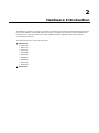
Hardware Introduction
The EPM Series expansion modules are designed to work with Moxa’s V2422 and V2426 embedded computers.
By providing different modules with different connectors, the EPM series offers the greatest flexibility and
convenience for users who would like to easily establish industrial applications that require different
communication interfaces.
The following topics are covered in this chapter:
Appearance
EPM-3032
EPM-3112
EPM-3337
EPM-3438
EPM-3552
EPM-DK01
EPM-DK02
EPM-3338
EPM-DK03
Dimensions
V2400 Series Expansion Modules
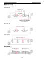
Hardware Introduction
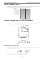
Appearance
EPM-3032
EPM-3112
EPM-3337
EPM-3438
2-2
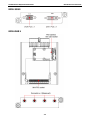
V2400 Series Expansion Modules
Hardware Introduction
EPM-3552
EPM-DK01
2-3
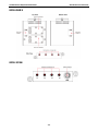
V2400 Series Expansion Modules
Hardware Introduction
EPM-DK02
EPM-3338
2-4
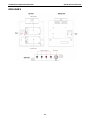
V2400 Series Expansion Modules
Hardware Introduction
EPM-DK03
2-5
V2400 Series Expansion Modules
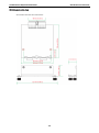
Hardware Introduction
Dimensions
All modules share the same dimensions.
2-6
3
3.
Hardware Connection Description
In this chapter, we show how to connect the embedded computers to the network and to various devices.
The following topics are covered in this chapter:
Installing the EPM Expansion Modules
Connecting Data Transmission Cables
EPM-3032 Serial Port Module
EPM-3337 Wireless/GPS Module
EPM-3438 DI/DO Module
EPM-3112 CAN Bus Module
EPM-DK01 Module: mini PCI + mini PCIe Sockets
EPM-3552 Display Module
EPM-DK02 Module: 2 mini PCIe Sockets
Installing Cellular/Wi-Fi Modules on the EPM-DK02, EPM-DK03, or EPM-3338
Configuring Power Controls on Socket 1
Installing a Cellular Module
Arranging Cables on the Wi-Fi or Cellular Modules
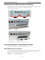
V2400 Series Expansion Modules
Hardware Connection Description
Installing the EPM Expansion Modules
The EPM series expansion modules are designed to work with Moxa’s V2422 and V2426 embedded computers.
Below we describe how to insert the modules into the embedded computer slots.
1. Remove the module cover screws.
2. Remove the cover from the slot.
3. Gently insert the module into the slot.
4. When finished, tighten the screws to hold the module in place.
Connecting Data Transmission Cables
In this section we explain how to connect the EPM modules to devices.
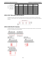
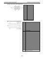
EPM-3032 Serial Port Module
Use a serial cable to plug your serial device into the module’s serial port. Serial ports 1 and 2 have male DB9
connectors and can be configured for RS-232, RS-422, or RS-485 communication by software. The pin
assignments are shown in the table at the top of the page following.
DB9 Male Port
RS-232/422/485 Pinouts
3-2
V2400 Series Expansion Modules
Hardware Connection Description
Pin
RS-232
RS-422
RS-485
RS-485
(4-wire)
(2-wire)
1
DCD
TxDA(-)
TxDA(-)
–
2
RxD
TxDB(+)
TxDB(+)
–
3
TxD
RxDB(+)
RxDB(+)
DataB(+)
4
DTR
RxDA(-)
RxDA(-)
DataA(-)
5
GND
GND
GND
GND
6
DSR
–
–
–
7
RTS
–
–
–
8
CTS
–
–
–
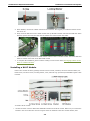
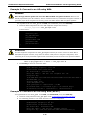
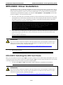
EPM-3337 Wireless/GPS Module
The EPM-3337 module comes with 4 connectors that can be used to connect antennas, including 2 Wi-Fi
antennas, 1 cellular antenna, and 1 GPS antenna. Refer to the following figure for the location of the different
antennas.
EPM-3438 DI/DO Module
The EPM-3438 module comes with 8 digital input channels and 8 digital output channels. See the following
figures for pin definitions and wiring methods.
Digital Input
Digital Input
Dry Contact Wiring
Wet Contact Wiring
Digital Output Wiring
3-3
V2400 Series Expansion Modules
Hardware Connection Description
EPM-3112 CAN Bus Module
The EPM-3112 offers two CAN bus ports with DB9 male connectors. Use a cable to plug your CAN device into
the module’s serial port. The pin assignments are shown in the following table:
DB9 Male
CAN bus Pinouts
PIN
CAN
1
–
2
CAN-L
3
–
4
–
5
–
6
–
7
CAN-H
8
–
9
–
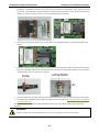
EPM-DK01 Module: mini PCI + mini PCIe Sockets
The EPM-DK01 offers a mini-PCI and a mini-PCIe sockets, allowing users to insert a mini-PCI or a mini-PCIe
card. See the following figure for the specific locations when installing these cards. Meanwhile, if you need to
connect the antenna, use the connectors on the exterior panel.
EPM-3552 Display Module
The EPM-3552 display modules comes with a VGA connector and a DVI-I connector. Use a cable to connect the
display to the connector on the module.
The pin assignments are shown in the tables on the next page.
3-4
V2400 Series Expansion Modules
Hardware Connection Description
D-Sub 15 Connector Pin Assignments
Pin No.
Signal Definitions
1
RED
2
GREEN
3
BLUE
4
–
5
GND
6
CRT_DETECT#
7
GND
8
GND
9
+5V
10
GND
11
–
12
DDC_DATA
13
HSYNC
14
VSYNC
15
–
DVI-I Connector Pin Assignments
Pin No.
Signal Definition
1
T.M.D.S. Data2-
2
T.M.D.S. Data2+
3
T.M.D.S. Data2/4 Shield
4
T.M.D.S. Data4-
5
T.M.D.S. Data4-
6
DDC Clock
7
DDC Data
8
Analog Vertical Sync
9
T.M.D.S. Data1-
10
T.M.D.S. Data1+
11
T.M.D.S. Data1/3 Shield
12
T.M.D.S. Data3-
13
T.M.D.S. Data3+
14
+5V Power
15
Ground (return for +5V, HSync, and VSync)
16
Hot Plug Detect
17
T.M.D.S. Data0-
18
T.M.D.S. Data0+
19
T.M.D.S. Data0/5 Shield
20
T.M.D.S. Data5-
21
T.M.D.S. Data5+
22
T.M.D.S. Clock Shield
23
T.M.D.S. Clock+
24
T.M.D.S. Clock-
C1
Analog Red
C2
Analog Green
C3
Analog Blue
C4
Analog Horizontal Sync
C5
Analog Ground
(analog R, G, B return)
3-5
V2400 Series Expansion Modules
Hardware Connection Description
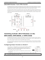
EPM-DK02 Module: 2 mini PCIe Sockets
The EPM-DK02 has two mini PCIe sockets that may be used for cellular communications expansion. The figures
below show the slots’ specific locations. Note that while both sockets provide a mini PCIe interface, socket one
supports either mini PCIe or USB 2.0 signals, whereas socket two only supports USB 2.0 signals.
Connect the cellular module to the mini PCIe socket, and insert the SIM card into the SIM card holder. Be sure
to tighten the screw in the screw holder so that the module will be firmly installed. Note that the second SIM
card holder is located on the back of the module. If you need to connect the antenna, use the connectors on the
exterior panel.
Installing Cellular/Wi-Fi Modules on the
EPM-DK02, EPM-DK03, or EPM-3338
The EPM-DK02/03/3338 has two mini PCIe sockets that allow users to insert two mini PCIe cards for cellular or
Wi-Fi communication. Note that while both sockets provide a mini PCIe interface, socket 1 supports either mini
PCIe or USB 2.0 signals, whereas socket 2 only supports USB 2.0 signals.
Users may purchase the cellular and Wi-Fi modules for the EPM-DK03 separately. The instructions for installing
the cellular and Wi-Fi modules follow. For the convenience of installing the antenna, always install the module
on Socket 2 first.
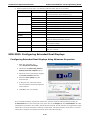
Configuring Power Controls on Socket 1
To use socket 1 as a USB interface, the user must allow the platform’s GPIO to
control the power; in contrast, for the PCIe interface the power must be
constantly on. These power controls must first be set at the hardware level,
using the jumper shown in the figure at right.
1. To enable GPIO control of power for a USB interface, place the jumper on
pins 1 and 2.
2. To disable power controls for an always-on PCIe interface, place the jumper on pins 2 and 3.
NOTE
This jumper configuration is for socket 1 only.
3-6
V2400 Series Expansion Modules
Hardware Connection Description
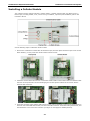
Installing a Cellular Module
The cellular accessory package includes a cellular module, a cellular antenna cable, four black screws, a
thermal pad, a locking washer, a nut, and an O-ring. In addition, a printed quick installation guide is also
included in the kit.
See the following steps to install the cellular module.
1. Remove the membranes on both sides of the thermal pad, and then place the thermal pad on the socket.
When finished, you may insert the cellular module into the socket.
2. Fasten the module with 2 black screws. Connect the antenna cable on the module. Make sure that the cable
has been securely fastened. See the following figures for the specific locations of the screws and the
antenna cable connector.
3. Insert the connector of the antenna cable into the O-ring. Remove the black cover from the antenna hole in
the front side of the EPM-3338 module, and then insert the connector. Insert the locking washer first, and
then fasten the nut to secure the connector (see figure on next page for detailed pictures).
3-7
V2400 Series Expansion Modules
Hardware Connection Description
4. When finished, connect the cellular antenna to the connector. We suggest you install the antenna on the
hole X2 or X3.
5. Next, insert the SIM card for the cellular module. Pull up the SIM card slot and insert the SIM card. When
finished, replace the holder and slide the slot towards the catch to fasten the holder
6. You can use the same procedure to install another cellular module on another socket. The second SIM card
holder is located on the back of the EPM-3338 module
7. To complete the installation, please continue reading in to the section below, Arranging Cables on the
Wi-Fi or Cellular Modules.
Installing a Wi-Fi Module
Moxa’s Wi-Fi module accessory package includes a Wi-Fi module, a bracket, two Wi-Fi antenna cables, four
black screws, two silver screws, a locking washer, a nut, and an O-ring. A printed quick installation guide is also
included.
To install a Wi-Fi module:
1.
Use the two silver screws to fasten the stabilization bracket to the Wi-Fi module. Make sure you connect the
bracket in the correct direction: the two tongues which are attached to the Wi-Fi module should, after
3-8
V2400 Series Expansion Modules
Hardware Connection Description
installation, be positioned under the card (refer to the figure below for clarification). Insert the Wi-Fi module
into Socket 1, and then fasten with the bracket into place using the two black screws. Please note that Wi-Fi
module can only be inserted in Socket 1. See the following figures for details.
2.
Connect the two antenna cables on the module. Make sure that these cables are securely fastened on the
module.
3.
Insert the connector of the antenna cable into the O-ring. Remove the black cover from the antenna hole in the
front side of the EPM-3338 module, and then insert the connector. Place the locking washer on the connector,
and then fasten the nut to secure the connector.
4.
For best performance, the first connector should protrude from the X1 hole, and the second from the X4 hole.
5.
To complete the installation, please continue reading in to the section below, Arranging Cables on the Wi-Fi
or Cellular Modules.
When finished, you may mount the EPM-3338/DK03 module into one of Moxa’s V2400 Series embedded
computers
WARNING
The Wi-Fi module can only be inserted into socket 1. Do not attempt to force it into socket 2.
3-9
V2400 Series Expansion Modules
Hardware Connection Description
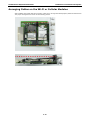
Arranging Cables on the Wi-Fi or Cellular Modules
After installing the cellular and Wi-Fi modules, make sure to arrange the cables properly within the chassis area.
The proper arrangement is shown in the following photos.
3-10
4
4.
Software Installation and Programming
Guide
In this chapter we discuss software installation and programming guide for the EPM expansion modules 3032,
3337, 3338, DK02, and DK03.
The following topics are covered in this chapter:
Linux System Peripherals Programming
Guide
EPM-3032: Driver Installation
EPM-3032: Configuring Baud Rate
EPM-3032: Configuring Serial Port Modes
EPM-3438: Driver Installation
EPM-3438: Programming Digital I/O or the
Counter
Implementing Timer Functions on Digital IO
Ports
EPM-3337 Driver Installation
EPM-3337: Operating Modes
EPM-3337: Setting up a Wi-Fi Connection
EPM-3337: Getting Wireless Card Information
EPM-3112: CAN Bus Interface
EPM-3112: Driver Installation
EPM-3112: Programming Guide
EPM-3552: Driver Installation
EPM-3552: Configuring the X Server
EPM-3552: Enabling a Dual Screen Display
EPM-3552: Configuring a Single Display
EPM-3552: Dynamically Changing the Display
Resolution
EPM-DK02: Driver Installation
EPM-3032: Driver Installation
EPM-3032: Configuring Serial Port Mode
EPM-3032: Changing the Software-Selectable
UART Mode
EPM-3438: Driver Installation
EPM-3438: Programming Guide
EPM-3337: Driver Installation
EPM-3338: Wireless Module Driver Installation
EPM-3338: Configuring a GPRS/HSDPA
Connection (no GPS)
EPM-3338: Configuring GPS
EPM-3338: Configuring a Wi-Fi/802.11
Connection
EPM-3112: Driver Installation
EPM-3112: Programming Guide
EPM-3552: Driver Installation
EPM-3552: Patch File Installation
EPM-3552: Display Configuration
EPM-3552: Configuring Extended Dual
Displays
EPM-DK02: Driver Installation
EPM-DK02: Controlling Power
EPM-DK03: Driver Installation
EPM-DK03: GPS Driver Installation
EPM-DK02: Installing the Kernel Module
EPM-DK03: Cellular Driver Installation
EPM-DK02: Configuring Power Controls
EPM-DK03: Wi-Fi Driver Installation
EPM-DK03: Driver Installation
EPM-DK03: Installing the GPS Test Clients
EPM-3338: Driver Installation
EPM-3338: Wi-Fi Module
EPM-3338: Cellular Module
EPM-3338: GPS Module
Windows System
EPM-DK03: Configuring the Cellular Software
Interface
EPM-DK03: Configuring a Wi-Fi Software
Interface
EPM-DK03: Getting Wi-Fi Information
V2400 Series Expansion Modules
Software Installation and Programming Guide
Linux System Peripherals Programming Guide
EPM-3032: Driver Installation
The EPM-3032 may be accessed over the Linux console as a tty device node. The Moxa driver creates a special
device node that is identified as a ttyM* device. The EPM-3032 device nodes are listed as /dev/ttyM8
and /dev/ttyM9, or alternately as /dev/ttyM16 and /dev/ttyM17. The UART API allows you to configure
these device nodes for RS-232, RS-422, 4-wire RS-485, or 2-wire RS-485.
The EPM-3032 driver is mxser.ko, and has been pre-installed
at /lib/modules/2.6.30-bpo.2-686/kernel/drivers/char/mxser.ko. It will be loaded
automatically when the system boots up.
EPM-3032: Configuring Baud Rate
Example 1: Set the Modulation Rate / Baud)
#define MOXA
0x400
#define MOXA_SET_SPECIAL_BAUD_RATE
(MOXA+100)
#define MOXA_GET_SPECIAL_BAUD_RATE
(MOXA+101)
#include
<termios.h>
struct termios term;
int
fd, speed;
fd = open(“/dev/ttyM8”, O_RDWR);
tcgetattr(fd, &term);
term.c_cflag &= ~(CBAUD | CBAUDEX);
term.c_cflag |= B4000000;
tcsetattr(fd, TCSANOW, &term);
speed = 115200;
ioctl(fd, MOXA_SET_SPECIAL_BAUD_RATE, &speed);
Example: Return the Modulation Rate / Baud
#define MOXA
0x400
#define MOXA_SET_SPECIAL_BAUD_RATE
(MOXA+100)
#define MOXA_GET_SPECIAL_BAUD_RATE
(MOXA+101)
#include
<termios.h>
struct termios term;
int
fd, speed;
fd = open(“/dev/ttyM8”, O_RDWR);
tcgetattr(fd, &term);
if ( (term.c_cflag & (CBAUD|CBAUDEX)) != B4000000 ) {
// On this line, you may insert a standard baud rate
} else {
ioctl(fd, MOXA_GET_SPECIAL_BAUD_RATE, &speed);
}
4-2
V2400 Series Expansion Modules
Software Installation and Programming Guide
ATTENTION
Maximum baud for the serial ports is 115,200; the stock serial ports on the V2400 series do not support other
bauds. However, the serial port expansion module does support modulation rates up to 921,600 baud.
Standard bauds are: 50, 75, 110, 134, 150, 200, 300, 600, 1200, 1800, 2400, 4800, 9600, 19200, 38400,
57600, 115200, 230400, 460800, 921600. To configure the above code for a standard baud connection, simply
insert the number at the indicated line.
If you use stty to get interface stats from a connection configured for a non-standard baud, the system will
return a rate of 0.
Modulation Rate Inaccuracy
Moxa’s drivers allow engineers to configure our serial devices for non-standard baud rates. Theoretically, these
devices may be set for any baud; however, in practice the only non-standard rates that will communicate at the
chosen modulation rate are whole number factors of the base rate, 921,600 Bd. For any non-standard rates
that are not a whole number factor of 921,600, there will be some inaccuracy in transmission speed relative to
the configured rate.
Standard bauds are 50, 75, 110, 134, 150, 200, 300, 600, 1200, 1800, 2400, 4800, 9600, 19200, 38400,
57600, 115200, 230400, 460800, and 921600. Moxa’s drivers allow for any whole number factor of 921,600 to
be used without any performance loss (i.e., inaccuracy or deviation from the TBR) in the configured modulation
rate. To calculate the relative inaccuracy for non-standard baud rates which are not a whole number factor of
921,600, users may use the formula below:
Root formula: Inaccuracy =
TBR – 921600 /(Factor + ENUM /8)
(TBR ) 100
The variables in this equation above are described below:
TBR = The Target Baud Rate, i.e., any non-standard modulation rate, in baud
Factor = 921,600/TBR (rounded down to the integer)
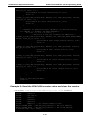
ENUM = 8 * (921600/Target baud - Factor) (Round up or down)
As an example, below we show you how to calculate the transmission inaccuracy at a target baud rate (TBR)
of 500,000 bps:
Target (non-standard) Baud Rate = 500,000
Factor =
921,600
500,000
= 1.8, then round down to the nearest integer for 1.
921,600
ENUM = 8 �500,000 � − 1 = 6.7, round to the nearest integer for 7.
Inaccuracy =
500,000 – 921600/(1 + 7/8)
�500,000� 100
= 1.696 = 1.7%
This result indicates that for a device configured at the non-standard rate of 500,000 Bd, the actual modulation
rate will deviate around 2% from the configured baud.
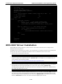
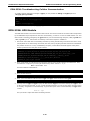
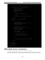
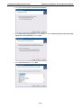
EPM-3032: Configuring Serial Port Modes
Use the setinterface command to retrieve the parameters of the serial port configuration. The usage
is $:~# setinterface [device node] [interface option]. The device node is the tty device to be
configured. For the serial ports, Moxa uses a proprietary driver whose device nodes are identified with the
marker M. Serial ports 1 and 2 (respectively) on card 1 are referred to as ttyM8 and ttyM9, and ttyM16 and
ttyM17 refer to ports 1 and 2 (respectively) on the second card. The interface option is a number between
0 and 4 that will determine what serial interface should be configured for the port in question. For example:
4-3
V2400 Series Expansion Modules
Software Installation and Programming Guide
$:~# setinterface /dev/ttyM8 0
sets the first serial port on the first card for RS-232 communications. Refer to the examples below for details.
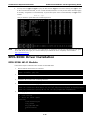
Moxa:~# setinterface
Usage: setinterface device-node [interface-no]
device-node - /dev/ttyMn; n = 0,1,2,...
interface-no
- following:
none - to view now setting
0 - set to RS232 interface
1 - set to RS485-2WIRES interface
2 - set to RS422 interface
3 - set to RS485-4WIRES interface
Moxa:~#
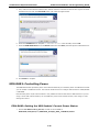
Checking Current Serial Settings
To check the current interface setting, type the following. The system should display a response as below.
Moxa: ~# setinterface /dev/ttyM8
Now setting is RS485-2WIRES interface.
In the example above, port 1 on card 1 is configured as a 2-wire RS-485 interface. After entering the lines of
code below, port 1 gets reset as an RS-422 interface.
Moxa: ~# setinterface /dev/ttyM8 2
Moxa: ~# setinterface /dev/ttyM8
Now setting is RS422 interface.
ATTENTION
Serial interfaces will shift device node identifiers depending upon the location and number of cards
mounted in the platform, e.g. if there are originally two cards mounted in the machine, and card number 1 is
removed, then the second card’s will change from /dev/ttyM16 and /dev/ttyM17 to /dev/ttyM8 and
/dev/ttyM9.
If a user wants to configure the machine for fixed serial interface device node identifiers, you can create a UDEV
rule in /etc/udev/rules.d/. For help with this, you may consult the UDEV manual files, another Linux
manual, or Moxa technical support for more details.
The system default for EPM-3032 interfaces is RS-232. By editing the device manager’s rule scripts, it is
possible to set all serial ports to one of the serial protocols (RS-485 or RS-422) instead. The steps describe how
to do so.
1. First remount the read-only root file system in writable mode.
Moxa:~# mount -o remount, rw /dev/hda1 /
2. Next, edit the Moxa’s custom rules file for the device manager. That will be found
at /etc/udev/rules.d/96-moxa.rules. Add the following command to 96-moxa.rules:
RUN+="/bin/setinterface /dev/ttyM%n 0”
# Set the device, EPM-3032, 0x1393:0x1022 default as 232 mode interface
DRIVERS=="mxser", ATTRS{vendor}=="0x1393", ATTRS{device}=="0x1022",
RUN+="/bin/setinterface /dev/ttyM%n 0"
"96-moxa.rules"
4-4
V2400 Series Expansion Modules
Software Installation and Programming Guide
ATTENTION
The VendorID for the EPM-3032 is 0x1393m, and the DeviceID is 0x1022.
3. To change the default serial interface mode, edit the setinterface command you have just added to the
Moxa rules file (/etc/udev/rules.d/96-moxa.rules). This will cause the Linux kernel to
automatically set the V2400 module to your preferred interface at every reboot.
•
•
•
•
For RS-232, use RUN+="/bin/setinterface /dev/ttyM%n 0"
For RS-485 2-wire, use RUN+="/bin/setinterface /dev/ttyM%n 1"
For RS-422, use RUN+="/bin/setinterface /dev/ttyM%n 2"
For RS-485 4-wire, use RUN+="/bin/setinterface /dev/ttyM%n 3"
4. When finished, you must un-mount the writable file system and reboot your computer
Moxa:~# umount /
Moxa:~# reboot
5. Once the computer restarts, confirm that the interfaces have been reset to the default settings.
Moxa:~# setinterface /dev/ttyM8
Now setting is RS485-2WIRES interface.
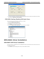
EPM-3438: Driver Installation
Upload the driver package to /dev/shm, a temporary file system on your computer.
root:~# scp epm3438-2.6.30-bpo.2-686.deb [email protected]:/dev/shm
Install the package
Moxa:~#
Moxa:~#
Moxa:~#
Moxa:~#
cd /dev/shm
mount -o remount, rw /
dpkg -i ./epm3438-2.6.30-bpo.2-686.de
umount /
After the driver installs, you can use lsmod to check if the epm3438 module is loaded in the kernel.
Moxa:~# lsmod|more
Module
epm3438
…
Size Used by
4620 0
To force the drivers to automatically load at boot time, you must edit /etc/init.d/moxainit.sh. Using your
editor of choice (below, we use VI), open up the moxainit script and then add the modprobe epm3438
and modprobe -r epm3438 lines.
Moxa:~# vi /etc/init.d/moxainit.sh
…
start)
…
modprobe moxa_device_dio device="v2400"
modprobe mxser
modprobe epm3438
…
;;
stop)
…
modprobe -r epm3438
modprobe -r moxa_swtd
modprobe -r moxa-device-dio
;;
...
4-5
V2400 Series Expansion Modules
Software Installation and Programming Guide
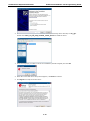
If you need to uninstall the driver, you can use this command:
Moxa:~# mount -o remount,rw /
Moxa:~# dpkg -r epm3438
Moxa:~# umount /
After uninstalling the module, it is advisable to comment out or remove the entries in your moxainit script.
EPM-3438: Programming Digital I/O or the Counter
Digital input/output channels for the V2400 series are provided by module EPM-3438. These channels can be
accessed at run-time for control or monitoring using the functions in the following sections. Each of the digital
output (DO) channels can be individually set to default to high or low. The digital input (DI) channels can be
used to detect the state change of the digital input signal. The header file of digital I/O functions is mxdgio.h,
which is located in the digit_input_change directory for Linux.
The EPM-3438 module may alternatively be used as a hardware counter, allowing engineers to log the number
of times an I/O event occurs as it switches from high to low. The hardware counter is exclusive to normal digital
I/O operations, but is useful for monitoring and analysis of state changes that occur continually at low
frequencies.
Moxa API Functions for DI/DO
Function
HANDLE mxdgio_epm3438_open(int HWIndex);
Description
This function opens access to the DIO device.
Input
<HWIndex> The first or second EPM-3438 board.
Output
None
Return
When successful, this function gives access to the DIO device. Otherwise, there is an error.
Function
void mxdgio_close(HANDLE fd);
Description
This function closes the access to the DIO device.
Input
<fd> The access to the device.
Output
None
Return
None
Function
int mxdgio_get_input_signal(HANDLE fd, int port);
Description
This function gets the signal state of a digital input channel.
Input
<fd> The access to the device.
<port> port #
Output
<state> DIO_HIGH (1) for high, DIO_LOW (0) for low
Return
Returns 1 for a high signal or 0 for a low signal, if successful. Otherwise, it returns a value of -1.
Function
int mxdgio_get_output_signal(HANDLE fd, int port);
Description
This function gets the signal state of a digital output channel.
Input
<fd> The access to the device.
<port> Port number
Output
None
Return
Returns 1 for a high signal or 0 for a low signal, if successful. Otherwise, it returns a value of -1.
Function
int mxdgio_set_output_signal_high(HANDLE fd, int port);
Description
This function sets digital output channel to high.
Input
<fd> The access to the device.
<port> Port number.
Output
none.
Return
When successful, this function returns 0. When an error occurs, it returns -1.
4-6
V2400 Series Expansion Modules
Software Installation and Programming Guide
Function
int mxdgio_set_output_signal_low(HANDLE fd, int port);
Description
This function sets a digital output channel to low.
Input
<fd> The access to the device.
Output
none.
Return
When successful, this function returns 0. When an error occurs, it returns -1.
<port> Port number.
Moxa I/O Control Definitions for the Counter Mode
This table shows the API for using the counter mode on the EMP-3438 module. The counter mode already
features de-bounce adjustments, so it should be usable immediately after programming and configuration. To
access the counter values, engineers must open a device node to retrieve the counter’s file descriptor. To read
the counter value on a single EPM-3438, use COUNTER_NODE1. If you have a second EMP-3438 module and
wish to read the counter for that, you may use COUNTER_NODE2.
#define
COUNTER_NODE1
"/dev/epm_3438_counter1"
#define
COUNTER_NODE2
"/dev/epm_3438_counter2"
Function
mxdgio_epm3438_get_counter(int fd);
Description
Gets the counter value
Input
<fd> The access to the counter device.
<port> Port number.
Output
none.
Return
the counter value
Function
mxdgio_epm3438_clear_counter(int fd);
Description
Clears the counter value
Input
<fd> The access to the counter device.
<port> Port number.
Output
none.
Return
0:clear success; -n: clear fail
mxdgio.h: The Moxa Digital Input/Output Headers
1. On the software CD that was included with your computer Moxa provides sample code to illustrate some
implementations of common DI/DO functions. To find these sample files, navigate to the directory
/V2100.V24XX/EPM3438/digit_input_change on the CD that is bundled with your module; there,
you will find the mxdgio.h file, which provides a convenient set of macros and an API for either digital I/O
or counter programming.
2. The default initial value for digital output is HIGH. If you want to set the initial output status to LOW, you
may instruct the kernel to load epm_3438.ko with a default LOW setting at boot time. To do this, add the
line epm3438_DO2LOW=1 in /etc/modules. For the setting to initialize, you must reboot your computer
or reload your kernel modules using the modprobe command:
$:~# modprobe –a
Moxa: ~# modinfo /lib/modules/2.6.30-bpo.2-686/kernel/drivers/char/epm_3438.ko
filename:
/lib/modules/2.6.30-bpo.2-686/kernel/drivers/char/epm_3438.ko
description: EPM-3438: DIO/Counter module
author:
[email protected]
license:
GPL
depends:
4-7
V2400 Series Expansion Modules
vermagic:
Software Installation and Programming Guide
2.6.30-bpo.2-686 SMP mod_unload modversions 686
parm:
epm3438_DO2LOW: Reset DO to LOW. 0. \
Set DO to High (default). 1. \
Set DO to LOW. (int)
Moxa: ~# mount -o remount, rw /
Moxa: ~# echo ‘# Load the EPM-3438 DIO driver’ >> /etc/init.d/moxainit.sh.
Moxa: ~# echo ‘modprobe epm_3438 epm3438_DO2LOW=1’ >> /etc/init.d/moxainit.sh
Moxa: ~# umount /
Registering Digital I/O Callback Events
Moxa provides a library of functions that allow a users to develop higher layer functions that respond to DI/O
state changes. These functions allow user applications to create specific responses to digital I/O events by
associating a callback function with an I/O event.
The source code files of the sample program are located in the
/example/V2100.V24XX/EPM3438/digit_input_change/ directory.
Four higher layer functions provide programmers with an API for timer callback events:
•
•
•
•
digit_io_timer_init
digit_io_timer_dispatch
digit_io_timer_add_callback
digit_io_timer_dispatch_quit
There are also four functions that give programmers an API for digital I/O callback events, available via
the digit_io_timer_add_callback function:
•
•
•
•
DGTIO_GET_INPUT_STATE_CHANGE
DGTIO_GET_INPUT
DGTIO_GET_OUTPUT
DGTIO_SET_OUTPUT
The following is an example of the initialization function for registering a callback event.
mngr = digit_io_timer_init();
…
if (digit_io_timer_add_callback (mngr, HWIndex, port, DGTIO_GET_INPUT_STATE_CHANGE,
interval, input_chg_cb, &port) < 0) {
…
}
if (digit_io_timer_add_callback (mngr, HWIndex, port, DGTIO_GET_INPUT, interval,
input_get_cb, &port) < 0) {
…
}
if (digit_io_timer_add_callback (mngr, HWIndex, port, DGTIO_SET_OUTPUT, interval,
output_set_cb, &port) < 0) {
…
}
if (digit_io_timer_add_callback (mngr, HWIndex, port, DGTIO_GET_OUTPUT, interval,
output_get_cb, &port) < 0) {
…
}
digit_io_timer_dispatch(mngr);
4-8
V2400 Series Expansion Modules
Software Installation and Programming Guide
Implementing Timer Functions on Digital IO Ports
Here are two examples ofDI/DO timer functions.
Example 1
File and Folder: /example/V2100.V24XX/EPM3438/digit_input_change/digit_io_timer.c
#include <stdio.h>
#include <stdlib.h>
#if !defined(_WIN32_WCE) && !defined(WIN32)
#include <time.h>
#endif
#include "digit_io_timer.h"
/* callback function */
static void
dgio_input_change_exec(DGIOMNGR *mngr, DGIOITEM *item)
{
int sig;
HANDLE fd=mngr->fd[item->HWIndex];
switch(item->mode)
{
case DGTIO_GET_INPUT:
sig = mxdgio_get_input_signal(fd, item->port);
item->cb(item->HWIndex, item->port, sig, item->arg);
break;
case DGTIO_GET_OUTPUT:
sig = mxdgio_get_output_signal(fd, item->port);
item->cb(item->HWIndex, item->port, sig, item->arg);
break;
case DGTIO_GET_INPUT_STATE_CHANGE:
sig = mxdgio_get_input_signal(fd, item->port);
if (item->last_signal!=sig)
{
item->cb(item->HWIndex, item->port, sig, item->arg);
}
break;
case DGTIO_SET_OUTPUT:
sig = item->cb(item->HWIndex, item->port, item->last_signal, item->arg);
if (sig)
{
mxdgio_set_output_signal_high(fd, item->port);
}
else
{
mxdgio_set_output_signal_low(fd, item->port);
}
break;
default:
return;
}
item->last_signal = sig;
4-9
V2400 Series Expansion Modules
Software Installation and Programming Guide
}
/**** release the timer operation ****/
static void
dgio_input_change_release(DGIOMNGR *mngr)
{
int i;
DGIOITEM *item, *next;
item=mngr->list;
while(item)
{
next = item->next;
free(item);
item = next;
}
for ( i=0; i<HW_TOTAL; i++ )
if (mngr->fd[i])
mxdgio_close(mngr->fd[i]);
}
/****
This function initializes a timer manager
Returns: Return a pointer to the manager.
****/
DGIOMNGR*
digit_io_timer_init(void)
{
DGIOMNGR *mngr;
mngr = (DGIOMNGR*) calloc(1, sizeof(DGIOMNGR));
if (mngr)
{
mngr->fd[0] = mxdgio_open();
#if 1 // Jared, 08-10-2010, support the second EPM-3438
mngr->fd[1] = mxdgio_epm3438_open(0); // The first EPM-3438
mngr->fd[2] = mxdgio_epm3438_open(1); // The second EPM-3438
#endif
if (mngr->fd[0] < 0)
{
free(mngr);
mngr = NULL;
}
}
return mngr;
}
/***
adds a digital IO timer with a selected operation mode
Inputs:
\
<mngr> timer manager
\
<HWIndex> specify which hardware device; \
0: embedded DIO,
\
1: EPM-3438 #1,
\
2: EPM-3438 #2
\
<port> specify which DIO pin
\
<mode> the operation mode on the port
\
4-10
V2400 Series Expansion Modules
Software Installation and Programming Guide
<interval> the interval (in milliseconds) between 2 calls \
to a user-defined function
\
<cb> the user-defined callback function
\
<arg> argument to the function
\
Returns:
\
0 on sucess, otherwise failure
\
***/
int
digit_io_timer_add_callback(DGIOMNGR *mngr, int HWIndex, int port, int mode, int
interval, digit_io_cb_t cb, void *arg)
{
DGIOITEM *item;
item = (DGIOITEM*) calloc (1, sizeof (DGIOITEM));
if (!item)
return -1;
item->next = mngr->list;
mngr->list = item;
item->cb = cb;
item->arg = arg;
item->HWIndex = HWIndex; // Jared, 08-10-2010, HWIndex to support multiple boards
item->port = port;
item->mode = mode;
item->interval = interval;
item->next_time = interval;
// Jared, 08-10-2010, HWIndex to support multiple boards
item->last_signal = mxdgio_get_input_signal(mngr->fd[HWIndex], port);
return 0;
}
void
digit_io_timer_dispatch_quit(DGIOMNGR *mngr)
{
if (mngr) mngr->dispatch = 0;
}
#define MAX_TIME 0XFFFFFFFF
/*** start and dispatch the timer operations
\
Inputs:
\
<mngr> the manager
\
Returns:
\
none
\
***/
void
digit_io_timer_dispatch(DGIOMNGR *mngr)
{
DGIOITEM *item;
unsigned int ms_sleep, n;
#if !defined(_WIN32_WCE) && !defined(WIN32)
struct timeval to;
#endif
mngr->dispatch = 1;
while(mngr->list && mngr->dispatch)
{
for (item = mngr->list; item != NULL; item = item->next)
{
4-11
V2400 Series Expansion Modules
Software Installation and Programming Guide
if (mngr->now_time < item->next_time) /* not yet */
continue;
/*** over due, executable ***/
n = mngr->now_time - item->next_time;
/*** move to the next time ***/
item->next_time = mngr->now_time+item->interval-n;
dgio_input_change_exec(mngr, item);
}
ms_sleep = MAX_TIME;
/*** get the amount of time to sleep ***/
for (item = mngr->list; item != NULL; item = item->next)
{
if (mngr->now_time < item->next_time) /*** not yet ***/
{
n = item->next_time - mngr->now_time;
if (n < ms_sleep) ms_sleep = n;
continue;
}
}
if (ms_sleep!=MAX_TIME)
{
#if !defined(_WIN32_WCE) && !defined(WIN32)
to.tv_sec = ms_sleep/1000;
to.tv_usec = (ms_sleep%1000)*1000;
if (select (0, NULL, NULL, 0, &to) != 0) /* sleep */
break;
#else
Sleep(ms_sleep);
#endif
mngr->now_time += ms_sleep;
}
}
dgio_input_change_release(mngr);
}
Example 2 (Implementing Timer Functions on Digital IO Ports)
File and Folder: /example/V2100.V24XX/EPM3438/digit_input_change/main.c
#include <stdio.h>
#include <stdlib.h>
#include "digit_io_timer.h"
static int
input_chg_cb(int HWIndex, int
{
printf("input_chg_cb()
return 0;
}
static int
input_get_cb(int HWIndex, int
{
printf("input_get_cb()
return 0;
}
static int
port, int sig, void *arg)
HWIndex %d port %d sig %d\n", HWIndex, port, sig);
port, int sig, void *arg)
HWIndex %d port %d sig %d\n", HWIndex, port, sig);
4-12
V2400 Series Expansion Modules
Software Installation and Programming Guide
output_set_cb(int HWIndex, int port, int last_sig, void *arg)
{
printf("output_set_cb() HWIndex %d port %d last sig %d\n", HWIndex, port,
last_sig);
last_sig++;
last_sig %= 2;
printf("new sig=%d\n", last_sig);
return last_sig;
}
static int
output_get_cb(int HWIndex, int port, int sig, void *arg)
{
printf("output_get_cb() HWIndex %d port %d sig %d\n", HWIndex, port, sig);
return 0;
}
#define INTERVAL
10000
int
#if defined(_WIN32_WCE)
WINAPI
WinMain( HINSTANCE hInstance, HINSTANCE hPrevInstance, LPTSTR lpCmdLine, int
nCmdShow )
#else
main(int argc, char *argv[])
#endif
{
DGIOMNGR *mngr;
int HWIndex;
int port;
int interval;
#if defined(_WIN32_WCE)
int
argc;
char cmdline[256], *argv[32];
WideCharToMultiByte(CP_ACP, 0, (LPCTSTR)lpCmdLine, 255, cmdline, 256, NULL,
NULL);
argc = split_line(argv+1, 32, cmdline)+1;
#endif
if (argc > 1) interval = atoi(argv[1]);
else interval = INTERVAL;
mngr = digit_io_timer_init();
if (mngr == NULL) {
printf("digit_io_timer_init() error\n");
return -1;
}
HWIndex=0; // HWIndex=0 for embedded DIO
for (port = 0; port < 1; port++) {
if (digit_io_timer_add_callback(mngr, HWIndex, port,
DGTIO_GET_INPUT_STATE_CHANGE, interval, input_chg_cb, &port) < 0) {
printf("add %d input change callback error\n", port);
return -2;
}
if (digit_io_timer_add_callback(mngr, HWIndex, port, DGTIO_GET_INPUT,
interval, input_get_cb, &port) < 0) {
printf("add %d input callback error\n", port);
return -3;
}
4-13
V2400 Series Expansion Modules
Software Installation and Programming Guide
if (digit_io_timer_add_callback(mngr, HWIndex, port, DGTIO_SET_OUTPUT, interval,
output_set_cb, &port) < 0) {
printf("add %d set output callback error\n", port);
return -4;
}
if (digit_io_timer_add_callback(mngr, HWIndex, port, DGTIO_GET_OUTPUT, interval,
output_get_cb, &port) < 0) {
printf("add %d get output callback error\n", port);
return -5;
}
}
/ / HWIndex=1 for EPM-3438 board #1; HWIndex=2, for EPM-3438 board #2
for (HWIndex = 0; HWIndex < HW_TOTAL; HWIndex++ ) {
for (port = 0; port < 8; port++) {
/* since list is LIFO last callbacks are added first */
if (digit_io_timer_add_callback(mngr, HWIndex, port, DGTIO_GET_INPUT_STATE_CHANGE,
interval, input_chg_cb, &port) < 0) {
printf("add %d input change callback error\n", port);
return -2;
}
if (digit_io_timer_add_callback(mngr, HWIndex, port, DGTIO_GET_INPUT, interval,
input_get_cb, &port) < 0) {
printf("add %d input callback error\n", port);
return -3;
}
if (digit_io_timer_add_callback(mngr, HWIndex, port, DGTIO_SET_OUTPUT, interval,
output_set_cb, &port) < 0) {
printf("add %d set output callback error\n", port);
return -4;
}
if (digit_io_timer_add_callback(mngr, HWIndex, port, DGTIO_GET_OUTPUT, interval,
output_get_cb, &port) < 0) {
printf("add %d get output callback error\n", port);
return -5;
}
}
}
digit_io_timer_dispatch(mngr);
return 0;
}
Example 3: Read the EPM-3438 counter value and clear the counter
File and Folder: /example/V2100.V24XX/EPM3438/digit_input_change/tcounter.c
#include
<stdio.h>
#include
<stdlib.h>
#include
<sys/time.h>
#include
<fcntl.h>
#include
<unistd.h>
#include
<signal.h>
#include
“mxdgio.h” // For counter reading or clear
#define COUNTER_NODE1 "/dev/epm_3438_counter1" // The first EPM-3438
#define COUNTER_NODE2 "/dev/epm_3438_counter2" // The second EPM-3438
int main(int argc, char * argv[])
4-14
V2400 Series Expansion Modules
Software Installation and Programming Guide
{
int retval;
int fd, fd2, len;
unsigned int counter_value;
fd=open(COUNTER_NODE1, O_RDONLY);
while( 1 ) {
printf("\nSelect a number of menu, other key to exit. \n\
1. Get counter value
\n\
2. Clear the counter
\n\
Others. quit
\n\
Choose : ");
scanf("%d", &retval);
if ( retval == 1 ) {
// Get counter without reset
counter_value = mxdgio_epm3438_get_counter(fd);
printf("EPM-3438 board #1 counter:%d\n", counter_value);
}
else if ( retval == 2 ) { // Get counter with reset
retval = mxdgio_epm3438_clear_counter(fd);
if ( retval < 0 )
printf("EPM-3438 board #1 counter reset fail\n");
}
else {
break;
}
}
close(fd);
return 0;
}
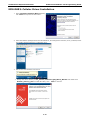
EPM-3337 Driver Installation
Moxa’s EPM-3337 module supports 3G, GPS, and Wi-Fi. This section introduces how to configure these
functions in the Linux platform.
The EPM-3337 driver operates in two modes: Linux and Windows. The default is Windows mode. During this
process, the user will run a script that will reset the driver from Windows mode to Linux mode.
1. Remount the root file system read-write:
Moxa:~# mount -o remount,rw /
2. Use dpkg to install the Debian package, epm3337.deb. This package file installs the driver and a few
scripts to configure the initialization process. epm3337.deb is not available on your software CD; you
must download it from the Moxa website
at: http://www.moxa.com/support/download.aspx?type=support&id=1799.
Moxa:/home# dpkg -i epm3337.deb
3. Moxa provides an automated shell script to perform the initial set up of the EPM-3337 module, to configure
the initialization process and set the EPM-337 to Linux mode. After installing epm3337.deb,
the moxa_hc25_setup_mdm.sh script should have been automatically installed in the /home directory.
This script only needs to be run once.
Moxa:/home# sh moxa_hc25_setup_mdm.sh
4. To see if the the kernel module is properly loaded and set up you should use the Debian lsusb command.
This will list the vendor and product IDs for all USB devices; the Sierra Wireless MC8305 HSPA card will
show one of either two IDs, depending on how it is set up. MDMNet mode is the default, and is used for
Windows, MDM mode is for Linux. Your device should be displaying the Linux ID:
4-15
V2400 Series Expansion Modules
Software Installation and Programming Guide
•
USB Device ID: 0681:0040 – Windows mode (MDMNet mode, default factory setting)
•
USB Device ID: 0681:0047 - for Linux (MDM mode)
Confirm that the installation has been successful and your card is accessible by querying the USB bus, as
below:
Moxa:/home# lsusb
Bus 001 Device 010: ID 0681:0047 Siemens Information and Communication
5. To allow the driver to load at startup you first need to alter the RC entry in the appropriate runlevel
commands directories. These are directories of symbolic links arranged by runlevel that point to the
initialization files located in /etc/init.d. To enable the file to be loaded at boot time, change the first letter
in the name of the symbolic link pointing to the EPM-3337 initialization file from N (igNore) to S (Start).
The default runlevel for the V24XX series computers is 2. To change the file name of the symbolic link,
navigate to /etc/rc2.d and issue the following command (this reboots the system to load the module):
Moxa:~# cd /etc/rc2.d
Moxa:/etc/rc2.d# mv N98moxa_hc25_load_driver S98moxa_hc25_load_driver & reboot
6. To get full wireless capabilities, you will also need to install software packages from an official Debian
repository; this will likely require an internet connection.
If you do not wish to expose the computer to the open Internet, then you may prepare a software CD in
advance and use that, instead. This will require an alteration of your apt.source list, however. For more
information on how to do this, consult this web page:
http://answers.oreilly.com/topic/19-how-to-install-debian-packages-from-cd-rom/
If you have not altered your apt.sources list and are connected to the Internet, then you should be able to
issue the commands below and automatically download the latest versions.
Moxa:/home# apt-get install wpasupplicant wireless-tools
7. To enable reate the correct links for wpa_supplicant
Moxa:/etc/network/if-up.d# ln -sf /etc/wpa_supplicant/ifupdown.sh wpasupplicant;
ln -sf /etc/wpa_supplicant/ifupdown.sh wpasupplicant;
ln -sf /etc/wpa_supplicant/ifupdown.sh wpasupplicant;
ln -sf /etc/wpa_supplicant/ifupdown.sh wpasupplicant
8. Now remount the root file system (/.) read-only using the unmount command, and reboot your device to
complete the installation.
Moxa:~# umount /; reboot
ATTENTION
The PPP v2.4.4 sometimes connects to the incorrect DNS; here are two workarounds:
1. Assign the DNS server manually: Comment out usepeerdns from /dev/pppt/chtgprs. Then
assign a DNS manually, in /etc/resolv.conf.
2. Use apt-get to remove ppp 2.4.4 and install ppp-2.4.5.deb
Moxa:~# apt-get remove ppp
Moxa:/home# dpkg -i ppp-2.4.5.deb
EPM-3337: Operating Modes
The EPM-3337 module has two operating modes, Normal and Multiplex:
Normal Mode Supports GPRS/HSDPA, but no GPS. The ports are allocated as follows:
•
Modem port: /dev/ttyACM0
•
Command port: /dev/ttyUSB0
Multiplexer Mode supports GPRS/HSDPA and GPS. A multiplexer program must be run to put the module into
multiplexer mode. The ports are allocated as:
•
Modem port: /dev/pts/0
4-16
V2400 Series Expansion Modules
•
•
Software Installation and Programming Guide
Command port: /dev/pts/1
GPS port: /dev/pts/2
ATTENTION!
If two EPM-3337 modules are being used, set module_num=2 in the EPM-3337 initialization script, found
at /etc/init.d/moxa_hc25_mux_script.
WARNING!
If GPS functionality is not needed, normal mode will give better performance.
EPM-3337: Normal Mode—GPRS/HSDPA
This section illustrates how to establish a point-to-point connection using pppd. The example files used are:
•
/etc/ppp/peers/chtgprs: the GPRS options file for chat
•
/etc/chatscripts/chtgprs-connect: chat connections file
•
/etc/chatscripts/chtgprs-disconnect: chat disconnection file
To set up GPRS using pppd:
1. Configure the file /etc/ppp/peers/chtgprs.
a. First, check if the name of the modem port is correct. It should be /dev/ttyACM0 for the first
module, /dev/ttyACM1 for the second one, and so on.
b. Make sure the local option is enabled. This option ignores the CD (Carrier Detect) signal.
2. Configure /etc/chatscripts/chtgprs-connect. For all AT commands, all options should be separated by
a comma, and all strings must be enclosed in double quotations.
a. First, check the packet data protocol type and Access point name of the ISP;
A basic command would be AT+CGDCONT=1, <PDP_type>, <APN>. If your PDP type and APN were
(respectively) IP and Internet, the above command would be written:
AT+CGDCONT=1, “IP”, “Internet”
b. Check the ATD dialout number: ATD <number>
c. Connect using the configuration files: pppd call chtgprs
3. Finally, confirm your configuration is correct by validating the connection state using ifconfig ppp0. If
the connection is ok, ifconfig will show an extended description of all internal data about the ppp0 (or pppn)
interface.
EPM-3337: Multiplexer Mode: GPS + GPRS/HSDPA
GPS functionality can only enabled when the module is set for multiplexer mode. In multiplexer mode, the
system uses a pseudo-terminal slave (pts) instead of reading serial ports (/dev/ttyACMx) to communicate.
To enable multiplexer mode, you must change the pppd configuration file found in the PPPd configuration folder
at /etc/pppd/peers by changing the modem port used entry to /dev/pts/0. This should be the first line
in your configuration file following the title. Simply comment out the /dev/ttyACM0 entry and on the next line
add the following line (as shown in the full peers file, displayed below):
/dev/pts/0
# modem port used
# File: /etc/ppp/peers/chtgprs
# See /etc/ppp/option for detail
#/dev/ttyACM0
# modem port used
/dev/pts/0
# modem port used
4-17
V2400 Series Expansion Modules
Software Installation and Programming Guide
115200
# speed
defaultroute # use the cellular network for the default route
noipdefault
usepeerdns
# use the DNS servers from the remote network
#nodetach
# keep pppd in the foreground
nocrtscts
# hardware flow control
lock
# lock the serial port
noauth
# don't expect the modem to authenticate itself
persist
# if a connection terminated, try to reopen
#demand
#Carrier Detect or Data Terminal Ready,
#choose modem(default) or local(ignore)
#modem
local
#Debug option--#You call tail -f /var/ppp.log &
#debug
#logfile /var/ppp.log
# Use the next two lines if you receive the dreaded messages:
#
#
No response to n echo-requests
#
Serial link appears to be disconnected.
#
Connection terminated.
#
lcp-echo-failure 4
lcp-echo-interval 65535
#add -V for debug
connect
"/usr/sbin/chat -v -f /etc/chatscripts/chtgprs-connect"
disconnect "/usr/sbin/chat -v -f /etc/chatscripts/chtgprs-disconnect"
The following steps illustrate how to set up GPS and use gpsd.
1. Set the module to enter multiplexer mode at startup by setting the initialization script, found in /etc/rc2.d,
to run at boot time.
Moxa:/etc/rc2.d# mv N99moxa_hc25_mux_script S99moxa_hc25_mux_script
2. Reboot and the script will switch the modem to run in multiplexor mode.
ATTENTION
The number assigned to the pseudo-terminals (pts) is affected by remote logins (e.g., ssh, or telnet). The
moxa_hc25_mux is run at startup to make sure the pseudo-terminals are generated as pts/0, ~/1, ~/2, etc, so
that remote logins will not interfere with your GPS connections.
WARNING
If you have previously configured the EPM-3337 for normal mode, be sure to return the runlevel command
/etc/rc2.d/S98moxa_hc25_load_driver
back to
/etc/rc2.d/N98moxa_hc25_load_driver.
4-18
V2400 Series Expansion Modules
Software Installation and Programming Guide
3. Reboot the computer.
4. The multiplexer will now automatically start at bootup and will be associated with the modem port
/dev/ttyACM0; it will generate three virtual terminal ports.
•
•
•
/dev/pts/0: Modem port
/dev/pts/1: Command port
/dev/pts/2: GPS port
If you have a second EPM-3337 module, the allocation will be:
•
•
•
/dev/pts/3: Modem port 2
/dev/pts/4: Command port 2
/dev/pts/5: GPS port 2
ATTENTION
When in multiplexer mode the serial terminal will only accept AT commands that end with \r\n (i.e.,
carriage return+newline). However, it is possible to set the serial emulator to automatically translate simple
carriage return symbols (\r) to carriage.return+newline (\r\n).
To enable automatic translation of carriage return (\r) to carriage return+newline (\r\n), you may reset the
terminal output flag with this command:
Moxa~#: stty -F /dev/pts/1 opost onlcr.
The tag onlcr will allow the serial terminal to automatically translate \r to \r\n. You can see the translation at
work in step 4, just below this note.
5. Enable the GPS port:
Moxa:~# cat < /dev/pts/1 & echo -e "AT^SGPSS=4\r" > /dev/pts/1
You may cancel the above command by using
Moxa:~#killall cat, or <ctrl>+C
6. Verify you are receiving NMEA data from the GPS port /dev/pts/2:
Moxa:~# cat < /dev/pts/2
$GPGSV,1,1,04,24,28,123,37,21,09,054,31,19,52,213,,23,47,270,*74
$GPGGA,061824.0,2458.835139,N,12133.055835,E,1,05,19.7,-103.5,M,,,,*14
$GPRMC,061824.0,A,2458.835139,N,12133.055835,E,,,290710,,,A*68
$GPGSA,A,3,24,21,06,31,16,,,,,,,,,25.5,19.7,18.5*29
$GPVTG,,T,,M,0.0,N,0.0,K*4E
7. Install the GPS daemon:
Moxa:~# apt-get install gpsd
8. Start gpsd to begin reading NMEA data from the GPS command port (/dev/pts/2):
Moxa:~# gpsd /dev/pts/2
9. For remote connections, you may use ssh to connect and issue the cgps command. If cgps is properly set
up, it will display the following information (screen shot at top of next page):
4-19
V2400 Series Expansion Modules
Software Installation and Programming Guide
To stop the GPS module from transmitting, send
AT^SGPSS=0
to the command port. The following code will allow you to monitor the cutoff of the signal. Use
Moxa:~#killall cat
to close the live display of the device data.
Moxa:~# cat < /dev/pts/1 &
Moxa:~# echo -e "AT^SGPSS=0\r" > /dev/pts/1
Moxa:~# killall cat
ATTENTION
For more information about gpsd the following references are available online:
•
The GPSD Unix manual page: http://gpsd.berlios.de/gpsd.html
•
The GPSD project website: http://catb.org/gpsd/
•
The GPSD coder’s website, at Savannah: https://savannah.nongnu.org/projects/gpsd/
•
The CGPS Unix manual page: http://www.pkill.info/linux/man/1-cgps/
•
The Debian User Forums: http://forums.debian.net/
•
The Debian Administrator’s Handbook: http://debian-handbook.info/browse/stable/
As described in this section, in multiplex mode the modem port is /dev/pts/0 instead of /dev/ttyACM0.
Check that the modem port is /dev/pts/0 at /etc/ppp/peers/chtgprs.
# See /etc/ppp/option for details
/dev/pts/0
# modem port used
115200
# speed
Now you can connect GPRS/HSDPA through pppd
Moxa:~# pppd call chtgprs
EPM-3337: Troubleshooting PPPD
To troubleshoot pppd problems, first put the daemon into debug mode by opening
/etc/ppp/peers/chtgprs and taking the steps on the page following:
•
First activate the debug mode and start writing to the logfile (/var/ppp.log) by un-commenting the
options; this is done by deleting the pound sign (#) at the front of the line.
•
Make the logfile verbose by adding the -V option to the /usr/sbin/chat command.
4-20
V2400 Series Expansion Modules
Software Installation and Programming Guide
#Debug option---
#You call tail -f /var/ppp.log &
debug
logfile /var/ppp.log
connect
"/usr/sbin/chat -v -V -f /etc/chatscripts/chtgprs-connect"
Now, /var/ppp.log will return much more detailed debugging messages.
EPM-3337: Setting up a Wi-Fi Connection
In this section we show you how to connect to an 802.11 access point using WPA2 (RSN). The connection
program we will use is wpa_supplicant.
The basic command to connect for WPA-supplicant is:
Moxa:~# wpa_supplicant -i <interface> -c <configuration file> -B
The -B option should be included because it forces the supplicant to run in the background.
Example 1: Connect to an AP using WEP
WARNING
Moxa strongly advises against the use of the WEP and WPA encryption standards. Both are now
officially deprecated by the Wi-Fi Alliance, and are considered insecure. To guarantee proper Wi-Fi encryption
and security, please use WPA2 with the AES encryption algorithm.
The SSID for this hypothetical network is test_wep, and the WEP encryption key is 1234567890
(hexadecimal).
A. First, create a WEP configuration file; write the sample below as
/etc/wpa_supplicant/test_wep.conf:
network={
ssid="test_wep"
key_mgmt=NONE
wep_key0=1234567890
wep_key1="abcde"
wep_key2="1234567890123"
wep_tx_keyidx=0
priority=5 }
B. Connect with the following command. If you are in the wpa_supplicant directory, then:
Moxa:~# wpa_supplicant -i wlan0 -c test_wep.conf -B
C. Use iwconfig to check the connection state. This will return something close to the following:
wlan0
IEEE 802.11abgn ESSID:"test_wep"
Mode:Managed Frequency:2.462 GHz Access Point: 00:1F:1F:8C:0F:64
Bit Rate=36 Mb/s Tx-Power=27 dBm
Retry min limit:7 RTS thr:off Fragment thr:off
Encryption key:1234-5678-90 Security mode:open
Power Management:off
Link Quality=37/70 Signal level=-73 dBm
Rx invalid nwid:0 Rx invalid crypt:0 Rx invalid frag:0
Tx excessive retries:0 Invalid misc:0 Missed beacon:0
4-21
V2400 Series Expansion Modules
Software Installation and Programming Guide
Example 2: Connect to an AP using WPA
WARNING
Moxa strongly advises against the use of the WEP and WPA encryption standards. Both are now
officially deprecated by the Wi-Fi Alliance, and are considered insecure, sub-standard encryption methods. To
guarantee proper Wi-Fi encryption and security, please use WPA2 with the AES encryption algorithm.
This hypothetical AP uses test_wpa as its SSID, and 1234567890 (ascii) as its WPA key.
A. Create the WPA configuration file in the WPA supplicant configuration directory:
/etc/wpa_supplicant/test_wpa-wpa2.conf
as shown below:
network={
ssid="test_wpa"
key_mgmt=WPA-PSK
proto=WPA RSN
pairwise=TKIP CCMP
group=TKIP CCMP
psk="1234567890"
}
ATTENTION
The WPA supplicant configuration file test_wpa-wpa2.conf may be used to connect to either WPA or
WPA2/RSN encrypted networks, using either the TKIP or CCMP protocol. Using this configuration, when
connecting to an access point WPA supplicant will automatically choose the most secure protocol available.
B. Connect with the following command:
Moxa:~# wpa_supplicant -i wlan0 -c test_wpa.conf –B
C. Use iwconfig to check the connection state:
wlan0
IEEE 802.11abgn ESSID: "test_wpa"
Mode: Managed Frequency: 2.462 GHz
Access Point: 00:1F:1F:8C:0F:64
Bit Rate=36 Mb/s Tx-Power=27 dBm
Retry min limit:7 RTS thr: off Fragment thr: off
Encryption key:
157A-1DBD-B0C3-7CC8-0F9C-D059-2881-F815-E4DB-3705-6969-8253-865E-4
DF0-FDB8-AEC1 [2]
Security mode: open
Power Management: off
Link Quality=34/70 Signal level= -76 dBm
Rx invalid nwid: 0 Rx invalid crypt: 0 Rx invalid frag:0
Tx excessive retries:0 Invalid misc:0 Missed beacon:0
Example 3: Connect to an AP using RSN (WPA2)
This hypothetical AP uses test_wpa2 as its SSID, and 1234567890 (ascii) as its WPA key.
A. Create the configuration file test_wpa-wpa2.conf, as described in the section just above.
B. Use iwconfig wlan0 to view details about the connection configuration.
wlan0
IEEE 802.11abgn ESSID:"test_wpa2"
Mode:Managed Frequency:2.462 GHz
Access Point: 00:1F:1F:8C:0F:64
Bit Rate=1 Mb/s Tx-Power=27 dBm
Retry min limit:7 RTS thr:off Fragment thr:off
Encryption key: 8546-8201-6DCA-8A37-6EE6-AD44-8D3F-6553 [2]
4-22
V2400 Series Expansion Modules
Software Installation and Programming Guide
ATTENTION
Here are some references for more information about WPA Supplicant:
The official homepage for WPA Supplicant: http://hostap.epitest.fi/wpa_supplicant/
The configuration
README: http://hostap.epitest.fi/gitweb/gitweb.cgi?p=hostap.git;a=blob_plain;f=wpa_supplicant/README
Wi-Fi Configuration Using WPA and WEP:
http://www.qnx.com/developers/docs/6.4.1/io-pkt_en/user_guide/wpa_background.html
ExampleNow page showing WPA Supplicant configuration and usage examples:
http://www.examplenow.com/wpa_supplicant/
EPM-3337: Getting Wireless Card Information
The program iw is a Linux configuration utility for wireless devices that can acquire more complete information
than iwconfig. Although still under development, it contains some useful functionality.
To get connection data, issue the command
Moxa:~# iw dev <interface> station dump:
Moxa:~# iw dev wlan0 station dump
Station 00:1f:1f:8c:0f:64 (on wlan1)
inactive time: 35696 ms
rx bytes:
98054
rx packets:
364
tx bytes:
733
tx packets:
7
signal:
-75 dBm
tx bitrate:
MCS 42 40Mhz
ATTENTION
More information about the iw utility may be found here:.
http://linuxwireless.org/en/users/Documentation/iw/
EPM-3112: CAN Bus Interface
The EPM-3112 module provides V24XX series computers with a CAN bus interface. CAN is a broadcast serial
bus standard for connecting electronic control units (ECUs). Each node is able to send and receive messages,
but not simultaneously: a message (consisting primarily of an ID—usually chosen to identify the
message-type/sender—and up to eight message bytes) is transmitted serially onto the bus, one bit after
another. This signal-pattern codes the message (in NRZ) and is sensed by all nodes.
The Moxa EPM-3112 module provides the CAN bus interface for industrial CAN communication. Users can use
Moxa’s CAN library or the local GNU/Linux device control interface (ioctl) to program reads, writes, and controls
for CAN devices.
EPM-3112: Driver Installation
CAN is a serial bus protocol for connecting and controlling electronic devices in harsh environments. A CAN bus
connects electronic control units (ECUs) so that each node may send and receive messages that consist of an
ID (to identify the message-type and sender) and up to eight message bytes.
4-23
V2400 Series Expansion Modules
Software Installation and Programming Guide
Moxa EPM-3112 module provides a CAN bus for industrial CAN communication. You may use Moxa’s CAN library
or the local GNU/Linux device control interface (ioctl) to program reads, writes, and controls for CAN devices.
To install the EPM-3112 kernel module:
1. Make the root file system writable:
Moxa:~# mount -o remount,rw /
2. Use the dpkg installer to install the epm3112.deb package. This package will automatically enable your
EPM-3112 module to load at boot time:
Moxa:/home# dpkg -i epm3112.deb
3. Re-mount the root system read-only:
Moxa:~# umount /
4. Then modprobe the module, moxa_can, or reboot your device to finish this installation.
EPM-3112: Programming Guide
Moxa’s CAN Library
Moxa’s CAN programming library, mxcanbus_lx.c, is an open-source CAN bus library. The
commands for mxcanbus_lx.c are documented in the following tables.
Moxa CAN Functions
Function
unsigned int mxcan_get_bus_timing (unsigned int fd)
Description
Get the bus timing of an open port.
Input
<fd> open file handle
Output
None
Return
0 on failure, otherwise the bus speed in KHz
Function
int mxcan_get_parameters (unsigned int fd, CANPRM *param)
Description
Return the parameters of an open port.
Input
<fd> open file handle
Output
<param> pointer to a structure of CANPRM
Return
0 on success. Otherwise return a negative value
Function
int mxcan_get_registers (unsigned int fd, unsigned char *buffer, int num)
Description
Return the register values of an open port.
Input
<fd> open file handle
<num> number of register values. For module with sja1000 chipset, the value
must be 32
Output
<buffer> point to a buffer for these values
Return
0 on success, otherwise failure
Function
int mxcan_get_stat (unsigned int fd, CANBST *stat)
Description
Return the statistics of an open port.
Input
<fd> open file handle
Output
<stat> point to a contianer of statistics
Return
0 on success, otherwise failure
Function
int mxcan_inqueue (unsigned int fd)
Description
Return the number of received bytes queued for an open port.
Input
<fd> open file handle
Output
None
4-24
V2400 Series Expansion Modules
Software Installation and Programming Guide
Return
< 0 on failure, the number of bytes
Function
unsigned int mxcan_open (int port)
Description
Open a CAN port using its local GNU/Linux device node ID
Input
<port> port number starting from 1. In Linux, port 1 will be opened as /dev/can0
Output
None
Return
0 on failure, otherwise return fd
Function
int mxcan_outqueue (unsigned int fd)
Description
Return the number of bytes an open port has queued for transmission
Input
<fd> open file handle
Output
None
Return
< 0 on failure, the number of bytes
Function
int mxcan_purge_buffer (unsigned int fd, unsigned int purge)
Description
Purge an open port’s buffers
Input
<fd> open file handle
<purge> 1: receive data buffer, 2: transmit data buffer, otherwise: both
Output
None
Return
0 on success, otherwise failure
Function
int mxcan_set_bus_timing (unsigned int fd, unsigned int speed)
Description
Set the bus timing for an open port.
Input
<fd> open file handle
<speed> bus timing in KHz. The available values are
5/10/20/40/50/80/100/125/200/250/400/500/666/800/1000
Output
None
Return
0 on success, otherwise returns a negative value
Function
int mxcan_set_nonblocking (unsigned int fd)
Description
Set an open file handle ID to be non-blocking.
Input
<fd> open file handle
Output
None
Return
0 on success, otherwise returns a negative value
Function
int mxcan_set_parameters (unsigned int fd, CANPRM *param)
Description
Set the parameters for an open port.
Input
<fd> open file handle
<param> pointer to a structure of CANPRM
Output
None
Return
0 on success, otherwise return a negative value
Moxa definitions for CAN bus Macros
#define mxcan_close(fd)
close((int)fd)
#define mxcan_read(fd, buffer, size, hndl)
read((int)fd, buffer, size)
#define mxcan_write(fd, buffer, size, hndl)
write((int)fd, buffer, size)
Moxa’s CAN Library: Sample Code
You may download the entire mxCAN bus library and sample code from the MOXA website.
http://www.moxa.com/support/support_home.aspx
4-25
V2400 Series Expansion Modules
Software Installation and Programming Guide
EPM-3552: Driver Installation
The Moxa EPM-3552 module provides VGA and DVI video display for Moxa’s V2422 and V2426 computers.
1. Make the root file system writable.
Moxa:~# mount -o remount,rw /
2. Install the package epm3552.deb. The EPM-3552 Debian software package is not available on your
software CD. It must be downloaded from the Moxa website, and may be found
at http://www.moxa.com/support/download.aspx?type=support&id=1799.
Moxa:/home# dpkg -i epm3552.deb
3. Install the gconf-editor. This is available using standard Debian repositories available on the Internet.
Moxa:~# apt-get install gconf-editor
4. Install grandr.
Moxa:~# apt-get install grandr
5. Start the GNOME desktop environment.
Moxa:~#/etc/init.d/gdm stop; /etc/init.d/gdm start
6. Disable the xrandr plug-in, because the gnome-settings-daemon gives poor x-rander support. In
gnome, launch Applications System Tools Configuration Editor, and then cancel xrandr active
options; you will find it in /apps/gnome_settings_daemon/plugins/xrandr/.
7. Re-mount the root file system as read-only.
Moxa:~# umount /
EPM-3552: Configuring the X Server
The V2422 and V2426 computers already support VGA and DVI display output, so this section illustrates how
to configure EPM-3552 to display a single desktop across dual monitors that are run out of the EPM-3552’s DVI
and VGA ports.
This configuration was successfully tested with two 18” and two 22” monitors sharing the same aspect ratio.
1. Connect your monitors to the EPM-3552 module before booting the computer.
2. After booting up, first back up the local interface’s configuration file, which is located
at /etc/X11/xorg.conf.
Moxa:~#cp /etc/X11/xorg.conf /etc/X11/xorg.conf.BAK
3. Next, rename the new configuration file xorg.conf-epm3552-dual to xorg.conf. This file should have
been installed with the Debian package file you installed in step 2, above.
Moxa:~#cp /etc/X11/xorg.conf-epm3552-dual /etc/X11/xorg.conf
4. Now, you may edit the new XOrg display configuration using your preferred text editor. For the built-in Intel
chipset, the only thing you should need to configure is the screen size. The value 3840x1080 is the
4-26
V2400 Series Expansion Modules
Software Installation and Programming Guide
maximum resolution (1920 x1080 x 2) of a desktop shared across two monitors. This is possible by
configuring the EPM-3552’s VGA and DVI interfaces to extend a display across both interfaces.
Section "Screen"
Identifier
"Screen_Intel"
Device
"Device_Intel"
Monitor
"VGA"
SubSection "Display"
Depth
24
Virtual 3840 1080
EndSubSection
EndSection
5. Set up the initial mode of the built-in VGA/DVI ports. The default value is the maximum resolution of the
monitor; you can adjust it in /etc/X11/Xsession.d/45xrandr.
a. To display an extended desktop use the configuration below:
#Resolution
res=1920x1080
#Extended mode
xrandr --output TMDS-1 --mode $res --right-of VGA --output VGA --mode $res
#Clone mode
b. To display a cloned desktop use the configuration below:
#Resolution
res=1920x1080
#Extended mode
#xrandr --output TMDS-1 --mode $res --right-of VGA --output VGA --mode $res
#Clone mode
xrandr --output TMDS-1 --mode $res --same as VGA --output VGA --mode $res
xrandr --output TMDS-1 --mode $res --same-as VGA --output VGA --mode $res
The tags are explained below:
output: Defines which interface the XRandR settings will apply to; DVI is TMDS-1, VGA is for VGA
right-of: Defines the relative position of the interface in the extended desktop
same-as: Sets clone mode
mode: Sets the screen resolution
6. Next start the X server:
Moxa: ~#/etc/init.d/gdm start
EPM-3552: Enabling a Dual Screen Display
To use two EPM3552 modules side-by-side you must first enable the second module by uncommenting the settings found
under the Device_DL2, Monitor_DL2, and Screen_DL2 sections in your new xorg.conf (formerly
xorg.conf-epm3552-dual) in the /etc/X11 directory. You must also uncomment the Screen 2 option in the Server
Layout section. You may review the sample file provided below for more details.
#Setting for the second EPM3552 module
Section "Device"
Identifier
"Device_DL2"
driver
"displaylink"
Option
"fbdev" "/dev/fb1"
EndSection
Section "Monitor"
Identifier
EndSection
"Monitor_DL2"
Section "Screen"
4-27
V2400 Series Expansion Modules
Software Installation and Programming Guide
Identifier
"Screen_DL2"
Device
"Device_DL2"
Monitor
"Monitor_DL2"
SubSection "Display"
Depth
24
EndSubSection
EndSection
Section "ServerLayout"
Identifier
"945G-Layout"
Screen 0 "Screen_Intel" 0 0
Screen 1 "Screen_DL1" LeftOf "Screen_Intel"
Screen 2 "Screen_DL2" LeftOf "Screen_DL1"
InputDevice
"Generic Keyboard" "CoreKeyboard"
InputDevice
"Configured Mouse" "CorePointer"
EndSection
When finished, connect a monitor to the second EPM-3552 module and reboot your system to activate the settings.
NOTE
For Linux systems, due to the limitations of the Linux RandR design the EPM-3552 display module cannot be
extended or mirrored across the V2422/V2426 computers’ built in VGA/DVI-I display interfaces. Likewise,
When using the EPM-3552 display module the display may not be mirrored or extended across the built-in
interfaces, either. When using the EPM-3552 display module, it is only possible to use one of the V24XX series’
built-in display interfaces a single, independent, standalone display.
EPM-3552: Configuring a Single Display
Back up your /etc/X11/xorg.conf file and then rename xorg.conf-epm3552-single to xorg.conf (see the
section above, on chipset configuration, if you need to review the commands). Next, start the X window to
launch a solitary display only on the EPM-3552 module.
EPM-3552: Dynamically Changing the Display Resolution
In this section we explain how to temporarily change the resolution and mode. To change the settings
permanently, modify the file /etc/X11/Xession.d/45xrandr. For the EPM-3552 module, only the current
driver can display the maximum resolution of a connected monitor. Therefore, even the “Modes” Option
in xorg.conf cannot adjust its resolution. For the built-in VGA/DVI port driven by an Intel chipset, use X RandR
or G RandR, located in System Administration Multiple Screens, to change the layout and resolution.
NOTE
Whenever you test new X RandR settings—such as when you adjust the resolution—the display will be reset to
cloned displays. So when using extended displays, whenever you have changed and tested a new setting make
sure to first re-set the display to Extended Mode before applying the settings and exiting the interface.
4-28
V2400 Series Expansion Modules
Software Installation and Programming Guide
ATTENTION
1. To make sure the kernel module loads properly, be sure to connect the monitor to the EPM-3552 module
before booting up the computer.
2. The built-in VGA/DVI port only supports clone and extended mode; dual head mode is not supported.
3. The X RandR project homepage may be found here:
http://www.x.org/wiki/Projects/XRandR
4. Click the following link for more information on Xorg
configuration: https://wiki.ubuntu.com/X/Config/Resolution
5. For the X RandR Unix manual page (i.e., man page), check here:
http://www.thinkwiki.org/wiki/Xorg_RandR_1.2
EPM-DK02: Driver Installation
Moxa’s EPM-DK02 module supports 2 mini PCIe slots for connecting mini PCIe modules.
•
Slot 1: Physical interface: mini PCIe
Electrical interface: mini PCIe, USB 2.0.
•
Slot 2: Physical interface: mini PCIe
Electrical interface: USB 2.0.
EPM-DK02: Installing the Kernel Module
1. Remount the root file system so it is writable:
Moxa:~# mount -o remount,rw /
2. Use dpkg to install the epmdk02.deb package, found at at EPM-DK02\package\epmdk02.deb.
Moxa:/home# dpkg -i epmdk02.deb
3. Mount the root file system (/) as read-only.
Moxa:~# umount /
4. Load the Moxa EPM-DK02 driver. To do so manually, use the following command:
Moxa:~# modprobe moxa_dk02
5. To automatically load the module at startup, add the following line into /etc/rc.local:
Moxa:~# echo ‘modprobe moxa_dk02’ >> /etc/rc.local
EPM-DK02: Configuring Power Controls
The EPM-DK02 module comes with the capability of automating a modular device’s power status. Please be
advised, however, that this function is provided primarily for powering on and off a GPRS/HSDPA card that use
a USB interface. It is NOT advisable to use this function with PCIe devices, because doing so may damage
them.
4-29
V2400 Series Expansion Modules
Software Installation and Programming Guide
WARNING
Use of the EPM-DK02’s onboard power controls for control of PCIe or USB-DOM devices is discouraged. Using
the onboard power controls for control of PCIe and USB-DOM devices may damage the devices (PCIe) or
corrupt data (USB-DOM). Any use of the EPM-DK02’s automated, onboard power controls with PCIe
and USB-DOM devices is undertaken at the user’s own risk.
Nor is it advisable to use the power control feature with USB DOM devices, because these devices involve the
mounting and unmounting of file systems, and while the Linux system will be able to automatically mount the
USB DOM file systems as they come online, without careful scripting it will not be able to automatically
unmount the file systems once the device goes offline.
The command for manipulating the PCIe card’s power feature is the mx-dk02 control. The precise syntax is as
follows, with slot_number indicating the number of the card slot located on the EPM-DK02 board itself (i.e.:
slot_number does not refer to module slots on the V24XX computer itself):
Moxa:~# mx-dk02-control <slot_number> <on/off flag>
The on flag is 0, and the off flag is 1..
Fox example, if you want to power off USB connectivity on slot 1, issue the following command:
Moxa:~# mx-dk02-control 1 0
Note that the slot number will depend on the position of the interface within the card:
Module 1
Module 2
Slot 1
Slot 3
Slot 2
Slot 4
Power button
Peripheral interfaces
ATTENTION
The major aim of the mx-dk02-control command is to reset a USB GPRS/HSPDA module; it is not
advisable to use the power on-off feature with a USB DOM module. This is because when a USB DOM module
is powered on, the Linux system will automatically mount its partitions, but when it is powered off the system
cannot automatically unmount its partitions.
Any use of the EPM-DK02’s automated, onboard power controls with PCIe interfaces and USB-DOM
devices is undertaken at the user’s own risk.
WARNING
Note that the power control is only suitable for devices that have a USB interface. If you are using a device with
a PCIe interface, do not enable the power on/off control function, since doing so could damage the device.
Any use of the EPM-DK02’s automated, onboard power controls with PCIe interfaces and USB-DOM
devices is undertaken at the user’s own risk.
4-30
V2400 Series Expansion Modules
Software Installation and Programming Guide
EPM-DK03: Driver Installation
The EPM-DK03 provides a combination GPS/GPRS card with an extra card slot where a second Wi-Fi, GPS, or
GPRS card may be installed. The kernel module for the GPS card bundled with the EPM-DK03 is precompiled
into the Linux kernel binary, so there is no need to install another one. The GPS card may be accessed and
controlled using the GPS daemon (GPSd), over the ports /dev/ttyACM0, or /dev/ttyACM1 (if a 2nd GPS
module is installed). To set up the kernel module:
1.
First check if the GPS card is transmitting raw data by issuing the following command to the device node,
/dev/ttyACM0. If no data is being returned by the card, first try adjusting the GPS antenna to troubleshoot
the problem. If there is no way of establishing reception, contact Moxa technical support at the phone
number provided in the title plate of this manual.
Moxa:~# cat /dev/ttyACM0
$GPGSV,1,1,04,24,28,123,37,21,09,054,31,19,52,213,,23,47,270,*74
$GPGGA,061824.0,2458.835139,N,12133.055835,E,1,05,19.7,-103.5,M,,,,*14
$GPRMC,061824.0,A,2458.835139,N,12133.055835,E,,,290710,,,A*68
$GPGSA,A,3,24,21,06,31,16,,,,,,,,,25.5,19.7,18.5*29
$GPVTG,,T,,M,0.0,N,0.0,K*4E
2.
Next, install the Linux GPS daemon from public repositories. GPSd is the GPS background interface that will
communicate with the raw GPS device. First, terminate the cat process you have just initiated using
Moxa:~# killall cat
and then install the GPS daemon:
Moxa:~# apt-get install gpsd
ATTENTION
If you do not wish to expose the computer to the open Internet, then you may prepare a software CD in
advance and use that, instead. This will require an alteration of your apt.source list, however. For more
information on how to do this, consult this web page:
http://answers.oreilly.com/topic/19-how-to-install-debian-packages-from-cd-rom/
3.
Start the GPS daemon:
Moxa:~# /etc/init.d/gpsd start
EPM-DK03: Installing the GPS Test Clients
Next, you must install test clients for gpsd. Xgps is a simple X interface test client that displays GPS position, time, and
velocity information along with the location of accessible satellites. Cgps is similar to xgps, but is able to run over a serial
or terminal interface and does not feature the pictorial satellite display.
1.
You may install cgps and xgps using Debian’s public repositories, accessible over the Internet:
Moxa:~# apt-get install gpsd-clients
ATTENTION
If you do not wish to expose the computer to the open Internet, then you may prepare a software CD in
advance and use that, instead. This will require an alteration of your apt.source list, however. For more
information on how to do this, consult this web page:
http://answers.oreilly.com/topic/19-how-to-install-debian-packages-from-cd-rom/
4-31
V2400 Series Expansion Modules
2.
Software Installation and Programming Guide
You may now use cgps and xgps to query the GPS daemon. Xgps is used on the desktop, and cgps is used
on the command line terminal, or over a serial emulator/interface. You may access either client by logging
in remotely, using SSH or a virtual desktop. To get a basic report on the current GPS data, call cgps on the
console:
Moxa~#: cgps
and you should a report that looks something like this:
NOTE
You may call the Unix man pages for more information on configuring and using the GPS daemon (man gpsd)
or the GPS client (man cgps). Or visit the GPSd project website for more completely documentation:
http://gpsd.berlios.de/
EPM-3338: Driver Installation
EPM-3338: Wi-Fi Module
Follow these steps to install the Wi-Fi module for the EPM-3338.
1.
Ensure that the device driver is activated:
Moxa:~# modprobe ath9k
Moxa:~# lsmod | grep ath
2.
Turn on the network interfaces wlan0 and wlan1:
Moxa:/home# ifconfig wlan0 up
3.
Install the Wi-Fi control and monitoring software:
Moxa:/home# apt-get install wpasupplicant wireless-tools
4.
Create the correct links for wpa_supplicant:
Moxa:/etc/network/if-up.d# ln -sf /etc/wpa_supplicant/ifupdown.sh wpasupplicant
Moxa:/etc/network/if-down.d# ln -sf /etc/wpa_supplicant/ifupdown.sh wpasupplicant
Moxa:/etc/network/if-pre-up.d# ln -sf /etc/wpa_supplicant/ifupdown.sh
5.
Edit wpa_supplicant.conf:
ctrl_interface=DIR=/var/run/wpa_supplicant
# home network;
# allow all valid cipher
Network={
ssid="Vodafone_AP"
scan_ssid=1
key_mgmt=WPA-PSK
psk="12345678"
}
4-32
V2400 Series Expansion Modules
6.
Software Installation and Programming Guide
To control or monitor the wireless client you may use the following command:
Moxa:/home@ wpa_cli -p /var/run/wpa_supplicant
NOTE
View the following reference for more information on wpa_supplicant and hostapd.
http://hostap.epitest.fi/wpa_supplicant/
Visit the following website for the wpa
configuration. http://hostap.epitest.fi/gitweb/gitweb.cgi?p=hostap.git;a=blob_plain;f=wpa_supplicant/README
View the following reference for more information on iw.
http://linuxwireless.org/en/users/Documentation/iw
EPM-3338: Cellular Module
Follow these steps to install the cellular module for the EPM-3338, which will use the PPP daemon to connect.
The pppd options file is located at /etc/ppp/peers/provider.
To set up pppd for cellular connectivity:
1.
Configure the /etc/ppp/peers/provider file. This file contains all of the information the server to
which you will be connecting using the point-to-point protocol:
a.
First, check if the name of module port is correct. It should be /dev/ttyUSB1 for the first module,
/dev/ttyUSB4 for the second one.
b. Make sure the local option is enabled. This option ignores the CD (Carries Detect) signal.
2.
Configure /etc/chatscripts/provider:
a. First, check that the packet data protocol type and access point name (APN, given by your ISP)
are correct. A basic command would be:
AT+CGDCONT=1, <PDP_type>, <APN>
If your PDP type and APN were (respectively) IP and Internet, the above command would be
written:
AT+CGDCONT=1, “IP”, “Internet”
b. Check the ATD dialout number:
ATD <number>
c. Connect using the configuration files: \
Moxa~#: pppd call chtgprs
d. Confirm your configuration is correct by reading the configuration file to connect:
Moxa~#: pppd call chtgprs
3.
Lastly, examine the connection status. If you have successfully connected, the device ppp0 (or pppn) has
been established. To check if this is the case, issue the command:
Moxa~#: ifconfig ppp0
You should see some output similar to this:
root@Moxa:~# ifconfig eth0 192.168.100.100
ppp0
Link encap Point-to-Point Protocol
inet addr 192.76.32.3 P-t-P 129.67.1.165 Mask 255.255.255.0
UP POINTOPOINT RUNNING MTU 1500 Metric 1
RX packets 33 errors 0 dropped 0 overrun 0
TX packets 42 errors 0 dropped 0 overrun 0
root@Moxa:~$
4-33
V2400 Series Expansion Modules
Software Installation and Programming Guide
EPM-3338: Troubleshooting Cellular Communication
To enable verbose debugging messages in pppd, you may enable the debug and logfile options in
/etc/ppp/peers/provider.
#Debug option---
#You call tail -f /var/log/ppp.log &
debug
logfile /var/log/ppp.log
The log will be available at /var/log/ppp.log for more detailed message.
EPM-3338: GPS Module
The EPM-3338 module comes with a built-in GPS module. The kernel module for the native GPS card provided
by the EPM-DK03 is precompiled into the Linux kernel binary, so there is no need to install another one. This
GPS module is read and managed by the gpsd daemon, and accessed through the ports /dev/ttyACM0 and
/dev/ttyACM1 (if a 2nd GPS module is installed). Follow these steps for installation:
1. First check if the GPS card is transmitting raw data by issuing the following command to the device node,
/dev/ttyACM0. If no data is being returned by the card, first try adjusting the GPS antenna to troubleshoot
the problem. If there is no way of establishing reception, contact Moxa technical support at the phone
number provided in the title plate of this manual.
Moxa:~# cat /dev/ttyACM0
$GPGSV,1,1,04,24,28,123,37,21,09,054,31,19,52,213,,23,47,270,*74
$GPGGA,061824.0,2458.835139,N,12133.055835,E,1,05,19.7,-103.5,M,,,,*14
$GPRMC,061824.0,A,2458.835139,N,12133.055835,E,,,290710,,,A*68
$GPGSA,A,3,24,21,06,31,16,,,,,,,,,25.5,19.7,18.5*29
$GPVTG,,T,,M,0.0,N,0.0,K*4E
2. Next, install GPSd, the GPS background interface that will communicate with the raw GPS device. First,
terminate the cat process you have just initiated using either <ctrl> + c, or :
Moxa:~# killall cat
and then install the GPS daemon:
Moxa:~# apt-get install gpsd
3. Start the GPS daemon:
Moxa:~# /etc/init.d/gpsd start
4. Next, you must install the GPS test clients cgps and xgps, which will interact with gpsd:
Moxa:~# apt-get install gpsd-clients
5. You may now use cgps and xgps to query the GPS daemon. Xgps is used on the desktop, and cgps is used
on the command line terminal, or over a serial emulator/interface. You may access either client by logging
in remotely, using SSH or a virtual desktop. To get a basic report on the current GPS data, call cgps on the
console:
Moxa~#: cgps
and you should a report that looks something like this:
4-34
V2400 Series Expansion Modules
NOTE
Software Installation and Programming Guide
Use the GNU system manual command to get more information on the GPS daemon interface and client:
Moxa ~#: man gpsd
Moxa ~#: man cgps
Or visit the GPS project website for more information: http://gpsd.berlios.de/
4-35
V2400 Series Expansion Modules
Software Installation and Programming Guide
Windows System
EPM-3032: Driver Installation
Before using the EPM-3032 expansion module, you need to update the driver. Install the driver before inserting
the expansion module in the slot.
1. Finde EPM3032Setup.exe on your software CD and execute it to install the driver. At the welcome screen,
click Next.
2. Click Next to install using default settings.
3. Click Next to start the installation.
4-36
V2400 Series Expansion Modules
Software Installation and Programming Guide
4. Click Close to complete the installation.
5. At this point, shut down the computer and insert the EPM-3032 expansion module into the embedded
computer, and then reboot the computer.
6. The system will locate the new hardware; select No, not this time and then click Next.
7. Select Install the software automatically and then click Next.
8. The driver will be installed automatically. The module should be listed in the Device Manager window. At
this point you can start using the module.
4-37
V2400 Series Expansion Modules
Software Installation and Programming Guide
EPM-3032: Configuring Serial Port Mode
Take the following steps to configure the operation mode of each COM port:
1. Go to the Control Panel Ports (COM & LPT) and select the COM port; e.g., MOXA Port 0 (COM1).
2. Right-click the COM port and then click Properties.
3. Click the Port Settings tab and then select the interface you would like to use.
4. Click OK to apply the settings.
In some situations, you may want to change the port name to match the name used by your program. Take the
following steps to change port names:
1. Go to Control Panel Multi-port serial adapters and select the adapter.
2. Right-click the adapter and select Properties.
4-38
V2400 Series Expansion Modules
Software Installation and Programming Guide
3. Click the Port Configuration tab, select the port, and then click Port Setting.
4. To change the port name separately uncheck Auto Enumerating COM Number.
5. Select the new port name and then click OK.
6. Make sure the port names are correct, and then click OK to activate the settings.
4-39
V2400 Series Expansion Modules
Software Installation and Programming Guide
7. Refer to Ports (COM & LPT) to verify that the port names have been changed.
NOTE
Make sure each port name is unique; using duplicate names will result in some devices being inaccessible.
EPM-3032: Changing the Software-Selectable UART Mode
The V24XX series features programmable UART that may be changed using system commands. The sample
code changing the UART mode that is shown here can be found on the Software DVD in \examples\C++\, as
UartMode.
The code snippet is as follows:
int port=0,mode=0;
int n=0;
WCHAR sin;
WCHAR wcs_port[3],wcs_mode[3];
printf("UART Mode Test Program\n");
printf("\t (0) Exit Program\n");
printf("\t (1) Display UART Mode\n");
printf("\t (2) Set UART Mode\n");
sin=getwchar();
n=_wtoi(&sin);
do
{
4-40
V2400 Series Expansion Modules
Software Installation and Programming Guide
switch (n)
{
// if char == '1', display the UART Mode
case 1:
printf("Input the Port Number (5~8) = \n");
wscanf(L"%s",wcs_port);
port=_wtoi(wcs_port);
mode=uart_getmode(port);
if(mode==(-1))
{
printf("Invalid value!!\n");
break;
}
printf("COM%d=%s\n",port,mode_array[mode]);
break;
// if char == '2', Set the UART Mode
case 2:
//Get Port Number
printf("Input the Port Number (5~8) = \n");
wscanf(L"%s",wcs_port);
port=_wtoi(wcs_port);
//Get Mode Value
printf("Input the Mode value (0 ~ 3) = ");
wscanf(L"%s",wcs_mode);
mode=_wtoi(wcs_mode);
}
//Set UART Mode
if(uart_setmode(port,mode)==-1)
{
printf("Invalid value!!\n");
printf("Set UART Mode Fail!!\n");
}
else
{
printf("COM%d=%s\n",port,mode_array[mode]);
}
break;
getwchar();
sin = getwchar();
n = _wtoi(&sin);
} while (n != 0);
return 0;
EPM-3438: Driver Installation
Before installing the EPM-3438, select counter mode or DI mode for the module.
If dip-switch 1 on the EPM-3438 is on, the DI0 will work in digital input port mode. The DI0 just reflects whether
the input signal status is HIGH or LOW. If DIP switch 2 on the EPM-3438 is on, the DI0 works as a 16-bit counter.
4-41
V2400 Series Expansion Modules
Software Installation and Programming Guide
The counter is increased when the input pulse is toggled from low to high. See the following figures for DIP
switch settings.
Before using the EPM-3438 expansion module, you need to update the driver. Be sure to install the driver
before inserting the expansion module in the slot.
Take the following steps to install the EPM-3438 module driver:
1. Run EPM3438Setup.exe to begin installation and then click Next.
2. Click Next to accept the default settings, and then click Next again to begin the installation.
3. Click Close to complete the installation, then then shut down the computer, insert the EPM-3438 expansion
module into the embedded computer, and then reboot the computer.
4-42
V2400 Series Expansion Modules
Software Installation and Programming Guide
4. The system should find the new hardware and install the driver automatically. Check the Windows Device
Manager to verify.
EPM-3438: Programming Guide
Some operations can be configured through programming; the following “DIO” example can be found on the
software DVD at \examples\C++\.
Moxa functions for DI/DO
Function
HANDLE mxdgio_epm3438_open(int HWIndex);
Description
This function opens access to the DIO device.
Input
<HWIndex> The first or second EPM-3438 board.
Output
None
Return
When successful, this function returns an access to the DIO device; otherwise, an error.
Function
void mxdgio_close(HANDLE fd);
Description
This function closes the access to the DIO device.
Input
<fd> The access to the device.
Output
None
Return
None
Function
int mxdgio_get_input_signal(HANDLE fd, int port);
Description
This function gets the signal state of a digital input channel.
Input
<fd> The access to the device.
<port> port #
Output
<state> DIO_HIGH (1) for high, DIO_LOW (0) for low
Return
Returns 1 for a high signal or 0 for a low signal, if successful. Otherwise, it returns a value of -1.
Function
int mxdgio_get_output_signal(HANDLE fd, int port);
Description
This function gets the signal state of a digital output channel.
Input
<fd> The access to the device.
<port> Port number
Output
None
Return
Returns 1 for a high signal or 0 for a low signal, if successful. Otherwise, it returns a value of -1.
Function
int mxdgio_set_output_signal_high(HANDLE fd, int port);
Description
This function sets a high signal to a digital output channel.
Input
<fd> The access to the device.
Output
none.
Return
When successful, this function returns 0. When an error occurs, it returns -1.
<port> Port number.
4-43
V2400 Series Expansion Modules
Software Installation and Programming Guide
Function
int mxdgio_set_output_signal_low(HANDLE fd, int port);
Description
This function sets a low signal to a digital output.
Input
<fd> The access to the device.
Output
none.
Return
When successful, this function returns 0. When an error occurs, it returns -1.
<port> Port number.
Moxa I/O control definitions for COUNTER
#define
COUNTER_NODE1
"/dev/epm_3438_counter1"
#define
COUNTER_NODE2
"/dev/epm_3438_counter2"
Function
int mxdgio_epm3438_get_counter(int fd);
Description
get the counter value
Input
<fd> The access to the counter device.
<port> Port number.
Output
none.
Return
the counter value
Function
int mxdgio_epm3438_clear_counter(int fd);
Description
Clear the counter value
Input
<fd> The access to the counter device.
<port> Port number.
Output
none.
Return
0:clear success; -n: clear fail
EPM-3337: Driver Installation
1. Navigate to the directory
\Drivers\HC25\HC25_0205ussb_ndis_driver
\install\program files\Siemens\
HC25 Connection Manager
and then double-click DPInst.exe. This will open the
installation wizasrd.
2. Accept the default configuration by clicking through,
and then wait for the driver to install.
3. You should see the drivers listed in the final window of
the Device Driver Installation Wizard. Click
Finish to complete the driver installation.
4-44
V2400 Series Expansion Modules
Software Installation and Programming Guide
4. Navigate to the \HC25\HC25_usb_ndis_driver\program files\ directory and double-click HC25
Connection Manager.msi.
5. Click Install.
6. During the installation process, if you encounter the following error message, just ignore it and click OK.
7. After the installation is completed, you should see Siemens HC25
HSDPA USB Modem, Siemens HC25 Wireless Ethernet
Adapter, and Siemens HC25 USB COM Port all listed in the
Windows Device Manager window.
4-45
V2400 Series Expansion Modules
Software Installation and Programming Guide
8. Change to the \HC25\HC25\Winmux2K directory and double-click wmux2k.exe.
9. Click Start Scan.
10. After the scan is completed you may click Install Driver.
11. Click Install Driver and then Continue Anyway once the scan is complete.
4-46
V2400 Series Expansion Modules
Software Installation and Programming Guide
12. Click OK to complete the installation.
13. Serial Multiplexer should appear in you the Device Manager window.
14. Right-click on Serial Multiplexer and select Properties. You will see that 3 virtual serial modem ports
have been generated; you can change the port numbers using the drop-down lists.
NOTE
Make sure each port name is unique; duplicate names will create glitches.
4-47
V2400 Series Expansion Modules
Software Installation and Programming Guide
EPM-3338: Wireless Module Driver Installation
1. If the Found New Hardware Wizard appears,
click Cancel to stop and exit the wizard.
2. Navigate to the Install_CD directory and double-click setup.exe to install the driver.
3. Select the language you want to use for the installation, and click Next (English default).
4. Click through to the license agreemet page, and select I accept the terms; then click Next.
4-48
V2400 Series Expansion Modules
Software Installation and Programming Guide
5. Select Install Client Utilities and Driver and then click Next.
6. Accept the default installation location by clicking through the next two screens.
7. Click through the message screen; you will want to accept the Atheros Client Utility.
8. Select Atheros Client Utility (ACU) and Supplicant and then click Next.
4-49
V2400 Series Expansion Modules
Software Installation and Programming Guide
9. Click Yes.
10. Click OK and wait for the driver to finish installing; then, click through to the restart screen.
11. You may select Yes, I want to restart my computer now to complete the installation, or elect to
continue installing other software first, before restarting the computer.
12. After the next reboot you should see Siemens HC25 HSDPA USB Modem, Siemens HC25 Wireless
Ethernet Adapter, and Siemens HC25 USB COM Port listed in the Windows Device Manager.
EPM-3338: Configuring a GPRS/HSDPA Connection (no GPS)
In this section we illustrate how to establish a connection using the Siemens HC25 Connection Manager.
1. Go to Control Panel System.
4-50
V2400 Series Expansion Modules
Software Installation and Programming Guide
2. Click Hardware Device Manager.
3. Right-click Serial Multiplexer and select Properties, then open the Port Settings tab.
4. First, verify the SIM card is ready; then open Virtual Port 2 and enter the AT command at+cpin?.
NOTE
Before you verify the SIM card status, check whether or not the PIN code has been submitted.
4-51
V2400 Series Expansion Modules
Software Installation and Programming Guide
5. Navigate to the SIM tab, select Verify PIN from the Action drop-down under the SIM Actions section.
6. Next, select the Connection tab and select the device from the drop-down list; then check the APN Name
box from the list below and enter your APN’s Name.
7. Click Connect to connect to the Internet and establish the wireless connection. You may check the wireless
connection by clicking on the Wireless Connections Properties in the Windows System Tray.
WARNING
Do not close the program while the connection is being established, or the device driver may become corrupted
and cease to work properly.
4-52
V2400 Series Expansion Modules
Software Installation and Programming Guide
8. At this point you can access this wireless network connection.
EPM-3338: Configuring GPS
GPS functionality is only enabled when the module is in multiplexer mode. A Winmux2K driver is available for
configuring the module in multiplexer mode. In multiplexer mode, the system will generate virtual COM ports
to communicate, and the modem port will become one of the virtual COM ports.
Take the following steps below to enable GPS functionality:
1. Start the Device Manager and check the three virtual COM ports, then start Terminal Emulator and open
the 2nd virtual COM port (COM18).
2. Enter at^sgpss=4 to enable GPS functionality.
4-53
V2400 Series Expansion Modules
Software Installation and Programming Guide
3. You may view the information returned by the GPS in a serial terminal (e.g., Windows HyperTerminal)
and verify that the device is working properly correct.
EPM-3338: Configuring a Wi-Fi/802.11 Connection
The EPM-3337 module includes a wireless module. In this section we explain how to connect to an access point
with WEP/WPA/WPA2(RSN) encryption.
To configure a wireless connection, do the following:
1. Double-click on the Atheros client utility shortcut on the desktop. Click on the Profile Management tab,
and then click the SCAN button.
2. Select the access point that you want to connect to and then click Activate.
4-54
V2400 Series Expansion Modules
Software Installation and Programming Guide
3. Enter the Profile Name and then select the Security tab.
1.
Moxa recommends selecting WPA2 as your security option; then click Configure.
Allow Association to Mixed
Check this box if the access point with which the client adapter is to associate
Cells
has WEP set to optional and WEP is enabled on the client adapter. Otherwise,
the client will be unable to establish a connection with the access point.
Profile Locked
This will lock the profile.
Limit Time for Finding Domain Check this box and enter the number of seconds (up to 300) after which the
Controller to XX Seconds
authentication process times out when trying to find the domain controller.
Entering zero is the same as disabling this feature, with no time limit
enforced when searching for domain controllers.
Group Policy Delay
Specify how much time elapses before the Windows logon process starts
group policy. Group policy is a Windows feature used by administrators to
specify configuration options for groups of users. The objective is to delay the
start of Group Policy until wireless network authentication occurs. Valid
ranges are from 0 to 65535 seconds. The value that you set goes into effect
after you reboot your computer with this profile set as the active profile.
This drop-down menu is active only if you choose EAP-based authentication.
WARNING!
Moxa strongly advises against the use of the WEP and WPA encryption standards. Both are now
officially deprecated by the Wi-Fi Alliance, and are considered insecure. To guarantee proper Wi-Fi encryption
and security, please use WPA2 with the AES encryption algorithm, and configure it with a strong password.
4-55
V2400 Series Expansion Modules
2.
Software Installation and Programming Guide
Configure a strong passphrase for your WPA2 network. This may be an 8 to 63 character ASCII passphrase,
or up to a 64 digit hexadecimal passphrase.
3.
If you want to use an Extensible Authentication Protocol, then you may choose the protocol from the
drop-down boxes at the right. If you wish to use a RADIUS server, then you will need to configure your
connection for 802.1X authentication. When you have configured the connection, click OK and exit the
setup wizard.
4.
The connection should now be established. You may check this using the Properties tab under the
Network Connections icon in the Windows Systray.
4-56
V2400 Series Expansion Modules
Software Installation and Programming Guide
EPM-3338: Getting Wireless Module Information
The Atheros Client Utility can be used to get wireless information and to manage wireless connections.
1. Double-click the Atheros client utility shortcut on the desktop and then select the Current Status tab.
2. Click the Advanced button. You will see the status of the current wireless connection.
EPM-3112: Driver Installation
Take the following steps to install the CAN BUS driver:
1. Double-click EPM-3112_V1.0.msi to open the setup wizard that will install the module. Click Next.
2. Click Next to accept the installer defaults, and then click through the next dialog to install the driver.
3. After the driver is installed, click Close to complete the driver setup.
4-57
V2400 Series Expansion Modules
Software Installation and Programming Guide
4. Next, open the Windows Device Manager, right click on the computer located at the top of the tree, and
select Scan for hardware change to finish the installation.
EPM-3112: Programming Guide
Moxa CAN Bus Library
int mxcan_close (int fd)
Description
Close an open port.
Input
<fd> the open port
Return Value
None
unsigned int mxcan_get_bus_timing (int fd)
Description
Gets the bus timing of an open port.
Input
<fd> the open port
Return Value
0 on failure, otherwise the bus speed in KHz
int mxcan_get_parameters (int fd, CANPRM * param)
Description
Gets the parameter of an open port.
Input
<fd> the open port
Output
< param> pointer to the CANPRM structure
Return Value
0 on failure, otherwise returns a negative value
int mxcan_get_registers (int fd, unsigned char * buffer, int num)
Description
Gets the register values of an open port.
Input
<fd> the open port
Output
< buffer > pointer to a buffer for these values
<num> number of register values; for a module with sja1000 chipset, the value must be 32
Return Value
0 on success; other numbers indicate failure
int mxcan_get_stat (int fd, CANBST * stat)
Description
Gets the statistics of an open port.
Input
<fd> the open port
Output
< stat > pointer to a container of the statistics
4-58
V2400 Series Expansion Modules
Return Value
Software Installation and Programming Guide
0 on success; other numbers indicate failure
int mxcan_inqueue (int fd)
Description
Gets the number of received bytes that are queued in the driver of an open port.
Input
<fd> the open port
Return Value
0 on failure; otherwise the number of bytes
int mxcan_open (int port)
Description
Open a can port given the port number.
Input
<port> port number starting from 1; in Linux, open port 1 will open /dev/can0
Return Value
-1 on failure; otherwise returns fd
int mxcan_outqueue (int fd)
Description
Gets the number of bytes waiting to be transmitted to a can port.
Input
<fd> the open port
Return Value
-1 on failure; otherwise the number of bytes
int mxcan_purge_buffer (int fd, unsigned int purge)
Description
Purges the buffers of an open port.
Input
<fd> the open port
Output
< purge> 1: received data buffer; 2: transmit data buffer; otherwise: both
Return Value
0 on success; otherwise failure
int mxcan_read (int fd, char * buffer, int size)
Description
Reads data into a buffer from an open port (the size should be a multiple of the CANMSG size)
Input
<fd> the open port
Output
<buffer> pointer to the buffer
Return Value
0 on failure (data not available); otherwise the number of bytes read
int mxcan_set_bus_timing (int fd, unsigned int speed)
Description
Sets the bus timing of an open port.
Input
<fd> the open port
Output
<speed> bus timing in Hz
Return Value
0 on success; otherwise returns a negative number
int mxcan_set_nonblocking (int fd)
Description
Sets the open fd to be non-blocking.
Input
<fd> the open port
Return Value
0 on success; otherwise returns a negative number
int mxcan_set_parameters (int fd, CANPRM * param)
Description
Sets the parameters of an open port.
Input
<fd> the open port
<param> pointer to the CANPRM structure
Output
<speed> bus timing in Hz
Return Value
0 on success; otherwise returns a negative number
int mxcan_set_read_timeout (int fd, unsigned int to)
Description
Sets data reading timeout of an open port.
Input
<fd> the open port
<to> timeout in milliseconds
Return Value
0 on success; otherwise failure
4-59
V2400 Series Expansion Modules
Software Installation and Programming Guide
int mxcan_set_write_timeout (int fd, unsigned int to)
Description
Sets data writing timeout of an open port.
Input
<fd> the open port
<to> timeout in milliseconds
Return Value
0 on success; otherwise failure
int mxcan_write (int fd, char * buffer, int size)
Description
Writes data to the open port
Input
<fd> the open port
<buffer> pointer to the data
<size> size of the data (should be a multiple of the CANMSG size)
Return Value
0 on failure; otherwise the number of bytes written
EPM-3552: Driver Installation
Take the following steps to install the EPM-3552 module driver.
ATTENTION
The driver must be installed first. Do not install the EPM-3552 module in the computer before
installing the driver.
1. Double click DisplayLink-5.5.29194.exe in the Driver folder on the software CD-ROM, and then click I
Accept to accept the software end user license agreement.
NOTE
During the installation, You may see a message like the one below appear, and then the screen may flash or go
black. Do not panic; simply wait until the process completes to continue.
4-60
V2400 Series Expansion Modules
Software Installation and Programming Guide
2. When finished, install the EPM-3552 module in your embedded computer. The following or similar message
will appear on the toolbar.
3. Assign a specific path for the installation driver by clicking Browse, and then select the following path
where the driver is located:
C:\Windows\system32\DRVStore\displaylin_0C8028254229DB9\
4. Select DisplayLinkUsbPort and then click Open.
5. Click OK to complete the installation.
NOTE
During the installation, the screen may flash or go black.
4-61
V2400 Series Expansion Modules
Software Installation and Programming Guide
EPM-3552: Patch File Installation
Known Technical Issues
The following technical issues will be apparent if you do not install the EPM-3552 patch file.
1. When powering off the V2422/2426 computer, the display connecting to an EPM-3552 module running
Extended Mode also shows the shutdown screen. Normally, the display connecting to the EPM-3552 module
should remain blank.
2. When the EMP-3552 module has been mounted and the V2422/2426 computer has been powered on, no
image shows on the display connected to the DVI-I connector of the V2422/2426 computer. Normally, the
image should be visible.
Installing the Patch File
1. Download the patch file from http://www.moxa.com/support.
2. Double click Setup.exe to start the Setup Wizard, and then click Next to continue.
3. Click Next to accept the default location, and then click through the next dialog to install the patch file.
4-62
V2400 Series Expansion Modules
Software Installation and Programming Guide
4. You will see a dialog like this, as the patch file is installed.
5. Click Close to complete the installation.
6. Restart the computer by clicking Start Turn Off Computer Restart.
EPM-3552: Display Configuration
When the EPM-3552 module has been installed, an icon appears on the taskbar to give you access to
the DisplayLink manager menu.
1. Click the DisplayLink icon on the taskbar. The menu will appear as shown below.
4-63
V2400 Series Expansion Modules
Software Installation and Programming Guide
2. Select an option from the menu. The following table lists which options are available.
Menu Options
Sub-menu Options
Screen Resolution
Descriptions
Displays a list of available resolutions. Some resolutions
may be enclosed by square brackets ([ ]).
Screen Rotation
Extend To
Normal
No rotation is applied to the display.
Rotated Left
Rotates the extended or mirrored display by 270 degrees.
Rotated Right
Rotates the extended or mirrored display by 90 degree.
Upside-Down
Rotates the extended or mirrored display by 180 degrees.
Right
Extends the display to the right of the main display.
Left
Extends the display to the left of the main display.
Above
Extends the display above the main display.
Below
Extends the display below the main display.
Extent
Extends your desktop onto the secondary display.
Set as Main
Sets the secondary display as the main display.
Monitor
Notebook Monitor
Switches off the display of an attached notebook and
Off
makes the DisplayLink display primary.
Mirror
Copies what is on the main display and reproduces it on
the secondary display.
Off
Switches off the secondary display
Fit to TV
Opens a GUI to change the size of the Windows desktop so
it fits on a V screen.
EPM-3552: Configuring Extended Dual Displays
Configuring Extended Dual Displays Using Windows Properties
1. Right-click the display and
select Properties Settings.
2. Checkmark the Extend my windows
desktop onto this computer option.
3. Adjust the screen resolution by dragging
the Screen resolution slide bar.
4. Select the Color quality from the
drop-down list.
5. In the gray zone, select the monitor
icons to match the physical arrangement
of the monitors.
6. Click OK to save your settings.
For more detailed settings, including the refresh rate, open the advanced settings dialog by clicking on
the Advanced button in the lower right corner, then click on the Adapter tab and List All Modes. All valid
combinations of resolution, color quality, and refresh rate are listed. For CRT monitors, we suggest using a high
refresh rate to avoid the discomfort caused by monitor flicker. Flat panel monitors do not flicker, so a lower
refresh rate is adequate. Screenshots are shown at the top of the next page.
4-64
V2400 Series Expansion Modules
Software Installation and Programming Guide
Configuring Extended Dual Displays Using DisplayLink Properties
1. From the taskbar, click the DisplayLink icon. This appears as a small computer monitor.
2. Select Extend.
EPM-3552: Configuring Mirrored Dual Diplays
Configuring Mirrored Dual Diplays Using DisplayLink Propertie
To use the Mirror Mode, you must use the Windows Properties dialog together with the DisplayLink
Properties dialog. To do this:
1. Right-click anywhere on the display desktop and
select Properties. This opens the Windows
Display Properties dialog (also available under the
control panel) shown at right.
2. Select the Settings tab, uncheck the Extend the
desktop onto this monitor option, and
click Apply.
3. From the taskbar, click the DisplayLink icon.
This appears as a small computer monitor.
4. Select Mirror from within the DisplayLink settings
dialog.
4-65
V2400 Series Expansion Modules
NOTE
Software Installation and Programming Guide
The display resolution of the primary display and the display may be changed to a lower resolution. In mirror
mode, both screens must output the same resolution, which may not be the maximum resolution of the display.
This mode is NOT recommended if you are using the display as the primary laptop display, since it is unlikely
to provide the optimum resolution for the display. See Setting the Display as the Primary Display section
for details.
EPM-3552: Configuring a Single Primary Display
Using Windows Properties
Take the following steps to make the display the primary display.
1. Right-click the display and then select Properties Settings.
2. Checkmark the This is my main monitor option.
3. Uncheck the Extend the desktop onto this monitor option.
4. Click Apply.
NOTE
On some PCs and laptops, it is necessary to disable the main display. This is because many primary graphics
card drivers tend to make the laptop screen the primary screen if it is enabled. The only workaround for this is
to disable the laptop screen to allow another screen to be the primary display.
To disable the main display, clear the Extend the desktop onto this monitor checkbox.
Using DisplayLink Properties
1. From the taskbar, click the DisplayLink icon.
2. Select Set as Main Monitor.
EPM-DK02: Driver Installation
1. Open the Windows Control Panel and click
on the Add Hardware icon. This will open
the Add Hardware Wizard. Click Next
when the wizard appears.
4-66
V2400 Series Expansion Modules
Software Installation and Programming Guide
2. Select Yes, I have already connected the hardware.
3. Select Add a new hardware device, and click Next, then select Install the hardware that I manually
select from a list (Advanced) and click Next.
4. Select Show All Devices and click Next.
4-67
V2400 Series Expansion Modules
Software Installation and Programming Guide
5. First, make sure the software CD that came with the module is inserted into the CD drive. Ignore the list of
manufacturers and click the Have Disk button just under the right window.
6. Select the mxdk02.inf from the path D:\EPM-DK02\driver in the CD-ROM, and click OK.
7. Select the EPM-DK02 Driver from the Model window and click Next, then Next again to install the driver.
8. Click Finish to complete.
EPM-DK02: Controlling Power
The EPM-DK02 module provides a power control function that lets you control the power of a USB device so that
you can enable or disable the device. This section introduces how to configure this function to enable/disable
a USB DOM.
Note that the power on/off control function is only suitable for devices that have a USB interface. If you are
using a device with a PCIe interface, do not enable the power on/off control function, since doing so could
damage the device.
EPM-DK02: Getting the USB Sockets’ Current Power Status
1. Execute mx-dk02-control_mfc.exe, located on the CD-ROM at
EPM-DK02\examples\C++\EPM-DK02_Example_Build_11060819\release.
4-68
V2400 Series Expansion Modules
Software Installation and Programming Guide
2. You may verify that the current power status for your selected devices matches that reported by the utility
by checking the Windows Device Manager.
EPM-DK02: Enabling/Disabling USB Socket Power
Take the following steps to disable the USB power-on socket:
1. Execute mx-dk02-control_mfc.exe.
2. Select the socket and change the status.
3. Click Apply for the changes to take effect.
4. Check the Windows Device Manager to see if the device is disabled.
EPM-DK03: Driver Installation
EPM-DK03: GPS Driver Installation
Follow these steps to install GPS driver for the EMP-DK03. Please note that these are the same instructions as
for the EPM-3338 module.
1. Click Cancel to stop searching device when you first install the module.
4-69
V2400 Series Expansion Modules
Software Installation and Programming Guide
2. Insert the Software Package CD into the CD-ROM drive, and change driver directory to drv_gps.
Double-click ublox_A4_U5_USB_drv3264_install_UI.exe to install the driver.
3. Select the language you want to use for the installation (default is English) and click OK.
4. When the u-blox GPS driver setup wizard appears, click Next to continue.
5. Click Agree to accept the license terms.
4-70
V2400 Series Expansion Modules
Software Installation and Programming Guide
6. Wait for driver installation wizard pop up. Click Next to begin the installation.
7. Wait for the process to end, and when you see the image below click Finish to complete the installation.
8. Check the Windows Device Manager to verify the device is enabled. You should see an entry titled
u-blox 6 GPS Receiver; select this and click on Properties to check configuration details for the GPS COM
port.
4-71
V2400 Series Expansion Modules
Software Installation and Programming Guide
9. To change the GPS receiver’s port number select Advanced under the Port Settings tab.
10. Select your desired COM port number from the drop-down menu in the lower. Click OK to finish.
11. You may now use a serial terminal like Windows HyperTerminal to view GPS data.
4-72
V2400 Series Expansion Modules
Software Installation and Programming Guide
EPM-DK03: Cellular Driver Installation
1. If the Found New Hardware Wizard appears,
click Cancel to stop and exit the wizard.
2. Insert the software package CD into the CD-ROM drive, and change driver directory to drv_Cellular\1 Driver
and double-click DriverInst.exe to install the driver.
3. Wait for the new hardware to be found.
1. Change the driver directory to drv_Cellular\2 Watcher\QMI_B3375_Watcher and double-click
Watcher_Generic_Q.msi’ to install the utility. Click ‘Next to continue.
4-73
V2400 Series Expansion Modules
Software Installation and Programming Guide
2. Select I accept the terms in the license agreement and click Next to continue.
3. Wait for the utility installation to complete, and click Finish to complete the installation.
EPM-DK03: Wi-Fi Driver Installation
1. If the Found New Hardware Wizard
appears, click Cancel to stop and exit the
wizard.
2. Insert the software package CD into the CD-ROM drive, and navigate to the driver directory at
D:\Software Package\drv_Wi-Fi\Install_CD. Double-click setup.exe to install the driver.
4-74
V2400 Series Expansion Modules
Software Installation and Programming Guide
3. Select the language you want to use for the installation, and click Next.
4. Wait for the driver installation to complete.
5. After the installation has completed, click Next, and then select I accept the terms of the license
agreement, and then Next again to continue.
6. Select Install Client Utilities and Driver, and then click Next to continue.
7. Verify that the file will be installed where you want it to be, and click Next to continue.
4-75
V2400 Series Expansion Modules
Software Installation and Programming Guide
8. Select the folder in the Windows Start Menu where you would like to have the program startup icon filed,
and click Next.
9. Click Next to continue to the adaptor configuration selection screen.
10. Select Qualcomm Atheros Client Utility (ACU) and Supplicant, and then click Next to continue.
11. Click Yes to continue.
12. Wait for the installation to complete.
13. Select Yes, I want to restart my computer now, and click Finish to complete.
14. Restart the computer to complete the installation.
EPM-DK03: Configuring the Cellular Software Interface
This section illustrates how to configure the cellular software interface for a wireless connection using
the Sierra Wireless AirCard Utility.
4-76
V2400 Series Expansion Modules
1.
Software Installation and Programming Guide
Execute the program: Start->Sierra Wireless->AirCard
Watcher. Click Connect to initiate a cellular connection. Do not
close the program when the connection is established or the
device driver may not work properly
2.
In Control Panel, select Wireless Network Connection
Status, and select Support tab to view the connection status.
Click Close to complete
3.
You may verify the cellular
connection by pinging the interface
once the connection is established.
4.
You may also check the connection status in Local Area
Connection Status dialog.
4-77
V2400 Series Expansion Modules
Software Installation and Programming Guide
EPM-DK03: Configuring a Wi-Fi Software Interface
This section introduces how to connect to an access point using WPA2 (RSN) encryption.
WARNING!
Moxa strongly advises against the use of the WEP and WPA encryption standards. Both are now
officially deprecated by the Wi-Fi Alliance, and are considered insecure. To guarantee proper Wi-Fi encryption
and security, please use WPA2 with the AES encryption algorithm.
5.
Run the Qualcomm Atheros Client Utility, select the Profile Management tab, and click Scan.
6.
Select the access point you want to associate with and click Activate.
7.
Name this configuration profile and enter the SSIDs with which you wish this client to associate. Then
change to the Security tab.
4-78
V2400 Series Expansion Modules
8.
Software Installation and Programming Guide
Moxa recommends selecting WPA2 as your security option; then click Configure.
Allow Association to Mixed
Check this box if the access point with which the client adapter is to associate
Cells
has WEP set to optional and WEP is enabled on the client adapter. Otherwise,
the client will be unable to establish a connection with the access point.
Profile Locked
This will lock the profile.
Limit Time for Finding Domain Check this box and enter the number of seconds (up to 300) after which the
Controller to XX Seconds
authentication process times out when trying to find the domain controller.
Entering zero is the same as disabling this feature, with no time limit
enforced when searching for domain controllers.
Group Policy Delay
Specify how much time elapses before the Windows logon process starts
group policy. Group policy is a Windows feature used by administrators to
specify configuration options for groups of users. The objective is to delay the
start of Group Policy until wireless network authentication occurs. Valid
ranges are from 0 to 65535 seconds. The value that you set goes into effect
after you reboot your computer with this profile set as the active profile.
This drop-down menu is active only if you choose EAP-based authentication.
WARNING!
Moxa strongly advises against the use of the WEP and WPA encryption standards. Both are now
officially deprecated by the Wi-Fi Alliance, and are considered insecure. To guarantee proper Wi-Fi encryption
and security, please use WPA2 with the AES encryption algorithm, and configure it with a strong password.
9.
Configure a strong passphrase for your WPA2 network. This may be an 8 to 63 character ASCII passphrase,
or up to a 64 digit hexadecimal passphrase.
4-79
V2400 Series Expansion Modules
Software Installation and Programming Guide
10. If you want to use an Extensible Authentication Protocol, then you may choose the protocol from the
drop-down boxes at the right. If you wish to use a RADIUS server, then you will need to configure your
connection for 802.1X authentication. When you have configured the connection, click OK and exit the
setup wizard.
11. The connection should now be established. You may check this using the Properties tab under the
Network Connections icon in the Windows Systray.
EPM-DK03: Getting Wi-Fi Information
You may use the management utility called Atheros Client Utility to help get wireless connection information.
1.
Run the Atheros Client Utility on the desktop and change it to the Current Status tab to view the Wi-Fi
connection status and information.
4-80
V2400 Series Expansion Modules
2.
Software Installation and Programming Guide
Click Advanced to view more detailed information. Click OK to exit.
4-81
A
A.
Video Performance Table for the
EPM-3552 Module
The EPM-3552 is a display module that provides a VGA and DVI output function for V2422and V2426 computers.
The module is used as the additional display option apart from the VGA/DVI provided by the V2422 and V2426
computers. Moxa provides the display performance tables so that users can optimize the EPM-3552 for specific
applications.
This table was produced from an actual performance test with the following parameters: video codec, audio
codec, film resolution, frame per second, and bit rates. We strongly suggest that you enable
the Hyper-Threading Technology function in the BIOS to ensure better performance of the EPM-3552
display module.
If you would like to use high resolution solutions for your applications, we suggest using the onboard VGA/DVI
outputs on the V2422/2426 computers. The EPM-3552 display module is suitable for the applications that
require lower resolution for displaying text and small-size figures.
V2400 Series Expansion Modules
Video Performance Table for the EPM-3552 Module
EPM-3552 Display Module Performance on
Linux Systems
Player
mplayer
On-board
VGA/DVI performance on
1.0rc2-4.3.2-DFSG-free
VGA/DVI
EPM-3552
performance on
V24XX
Model
Container
Video
Audio
Codec
Codec
Resolution
FPS
V2422/2426-LX
EPM-3552-LX
BitRate
System
Media
System
Media
(kbps)
CPU
Player
CPU
Player/CPU Configuration
loading
/CPU
loading
loading
Suggested
loading
WMV3X
WMV2X
MPEG-2
H.264 /
WMV
WMV3x
WMA9
1920 x 1080
29.97
15000
51.4
47.5
46.6
30.7
WMV
WMV3x
WMA9
1680 x 1050
29.97
12000
50.7
46.8
48.8
33
WMV
WMV3x
WMA9
1440 x 900
29.97
10000
50.1
46
49.9
33.5
WMV
WMV3x
WMA9
1280 x 720
29.97
8000
41
38.5
45.8
31.1
WMV
WMV3x
WMA9
1024 x 600
29.97
7000
29.8
28.4
48.3
33.9
WMV
WMV3x
WMA9
800 x 480
29.97
6000
20.9
20.1
33.9
23.8
WMV
WMV3x
WMA9
640 x 400
29.97
4000
14.4
13.7
22.7
16.2
WMV
WMV3x
WMA9
320 x 200
29.97
2000
6.5
6
8.1
6.5
WMV
WMV2x
WMA8
1920 x 1080
29.97
15000
49.1
45.5
46.7
32.4
WMV
WMV2x
WMA8
1680 x 1050
29.97
12000
48.8
44.9
48
33.4
WMV
WMV2x
WMA8
1440 x 900
29.97
10000
47
43.1
48.4
34
WMV
WMV2x
WMA8
1280 x 720
29.97
8000
42
38
46.4
32.5
WMV
WMV2x
WMA8
1024 x 600
29.97
7000
28.1
26.8
44.3
31.7
★
WMV
WMV2x
WMA8
800 x 480
29.97
6000
18.9
18
29.9
21.2
★
WMV
WMV2x
WMA8
640 x 400
29.97
4000
13
12.3
20
14.2
★
WMV
WMV2x
WMA8
320 x 200
29.97
2000
6
5.4
7.1
5.6
★
MPEG-PS
MPEG-2
ac3
1920 x 1080
29.97
15000
43.64
39.2
32
17.1
MPEG-PS
MPEG-2
ac3
1680 x 1050
29.97
12000
36.6
32.9
33.7
18.4
MPEG-PS
MPEG-2
ac3
1440 x 900
29.97
10000
27.9
25.4
34.4
18.8
MPEG-PS
MPEG-2
ac3
1280 x 720
29.97
8000
20.7
18.6
31.5
17.2
MPEG-PS
MPEG-2
ac3
1024 x 600
29.97
7000
15.2
13.6
32.2
17.8
★
MPEG-PS
MPEG-2
ac3
800 x 480
29.97
6000
10.9
9.7
22.7
13
★
MPEG-PS
MPEG-2
ac3
640 x 400
29.97
4000
7.6
6.5
16.1
9.1
★
MPEG-PS
MPEG-2
ac3
320 x 200
29.97
2000
3
2.5
4.9
3.1
★
MPEG-4
H.264/M
M4 AAC 1920 x 1080
29.97
15000
51.7
47.4
41.7
27.6
M4 AAC 1680 x 1050
29.97
12000
51.5
47.3
44.6
29.7
M4 AAC 1440 x 900
29.97
10000
44.7
42.1
45.6
30.2
M4 AAC 1280 x 720
29.97
8000
33
31.6
42.4
28.9
M4 AAC 1024 x 600
29.97
7000
24.5
23.4
42.4
29.1
★
M4 AAC 800 x 480
29.97
6000
18.2
17.6
30.3
21
★
M4 AAC 640 x 400
29.97
4000
12.9
11.9
20.8
14.6
★
M4 AAC 320 x 200
29.97
2000
5.9
5.5
7.4
5.8
★
MPEG-4
★
4 AVC
MPEG-4
H.264/M
4 AVC
MPEG-4
H.264/M
4 AVC
MPEG-4
H.264/M
4 AVC
MPEG-4
H.264/M
4 AVC
MPEG-4
H.264/M
4 AVC
MPEG-4
H.264/M
4 AVC
MPEG-4
H.264/M
4 AVC
A-2
V2400 Series Expansion Modules
AVI
AVI
MS/MPG
Video Performance Table for the EPM-3552 Module
pcm
1920 x 1080
29.97
15000
48.8
42.7
35.2
19.9
pcm
1680 x 1050
29.97
12000
38.3
34.2
36
21.1
pcm
1440 x 900
29.97
10000
28.9
26
36.7
21.2
pcm
1280 x 720
29.97
8000
21.4
19.2
34.2
19.4
pcm
1024 x 600
29.97
7000
15.9
14.1
32.7
19.2
★
pcm
800 x 480
29.97
6000
10.6
9.4
22.6
13.2
★
pcm
640 x 400
29.97
4000
7.2
6.1
15.4
8.8
★
pcm
320 x 200
29.97
2000
2.74
2
4.4
2.6
★
4v2
AVI
MS/MPG
4v2
AVI
MS/MPG
4v2
AVI
MS/MPG
4v2
AVI
MS/MPG
4v2
AVI
MS/MPG
4v2
AVI
MS/MPG
4v2
AVI
MS/MPG
AVI
AVI
DivX-5
mp3
1920 x 1080
29.97
15000
49.1
42.6
35.8
20.4
(DivX)
AVI
DivX-5
mp3
1680 x 1050
29.97
12000
37.9
34.4
36.8
21.4
AVI
DivX-5
mp3
1440 x 900
29.97
10000
28.6
26.1
36.9
21.7
AVI
DivX-5
mp3
1280 x 720
29.97
8000
21.5
19.6
34
20
AVI
DivX-5
mp3
1024 x 600
29.97
7000
15.9
14.2
33.8
20
★
AVI
DivX-5
mp3
800 x 480
29.97
6000
10.9
9.8
23
13.6
★
AVI
DivX-5
mp3
640 x 400
29.97
4000
7.5
6.6
16
9.3
★
AVI
DivX-5
mp3
320 x 200
29.97
2000
3.2
2.8
5
3.4
★
4v2
EPM-3552 Display Module Performance on
Windows Systems
Player
Media Player Classic - Home Cinema
On-board VGA/DVI
VGA/DVI performance on
v1.4.1.2834
performance on V24XX
EPM-3552
Film Parameters
Container Video
Audio
Codec
Codec
Resolution
FPS
V2422/V2426-XPE
EPM-3552
BitRate
System
Media Player
System
Media
(KBS/)
CPU
/CPU loading
CPU
Player/CPU Configuration
loading
1920 x 1080 29.97
15000
52.4
loading
95.9
47.8
WMV
WMV3x
WMA9
WMV
WMV3x
WMA9
1680 x 1050 29.97
12000
52
50.1
96.7
48.5
WMV
WMV3x
WMA9
1440 x 900
29.97
10000
50.1
48.4
92.7
47.9
WMV
WMV3x
WMA9
1280 x 720
29.97
8000
37.7
35.7
90.4
46.6
WMV
WMV3x
WMA9
1024 x 600
29.97
7000
29.2
27.7
74.9
35.8
WMV
WMV3x
WMA9
800 x 480
29.97
6000
23.1
21.6
67
26.3
★
WMV
WMV3x
WMA9
640 x 400
29.97
4000
23.5
21.9
53.6
22
★
WMV
WMV3x
WMA9
320 x 200
29.97
2000
10.5
9
23.1
10.7
★
WMV
WMV2x
WMA8
1920 x 1080 29.97
15000
48.1
46.9
92.5
47.2
WMV
WMV2x
WMA8
1680 x 1050 29.97
12000
46.1
44.8
91.8
46.4
WMV
WMV2x
WMA8
1440 x 900
29.97
10000
38.1
36.4
86.1
44.8
WMV
WMV2x
WMA8
1280 x 720
29.97
8000
29.4
28
75.7
36.4
WMV
WMV2x
WMA8
1024 x 600
29.97
7000
21.2
19.7
63.9
25.3
★
WMV
WMV2x
WMA8
800 x 480
29.97
6000
19.3
17.9
57
19.2
★
WMV
WMV2x
WMA8
640 x 400
29.97
4000
17.6
16.2
47.4
19.6
★
WMV
WMV2x
WMA8
320 x 200
29.97
2000
8.1
6.7
19.5
8.3
★
A-3
50.6
loading
Suggested
V2400 Series Expansion Modules
Video Performance Table for the EPM-3552 Module
MPEG-PS
MPEG-2
ac3
1920 x 1080 29.97
15000
42.6
MPEG-PS
MPEG-2
ac3
1680 x 1050 29.97
12000
36.2
34.7
94.5
46.4
MPEG-PS
MPEG-2
ac3
1440 x 900
29.97
10000
28.1
26.7
80.4
34
★
MPEG-PS
MPEG-2
ac3
1280 x 720
29.97
8000
21.7
20.1
68.8
24.9
★
MPEG-PS
MPEG-2
ac3
1024 x 600
29.97
7000
17
15.5
60.5
19.2
★
MPEG-PS
MPEG-2
ac3
800 x 480
29.97
6000
12.8
11.6
54.6
14.1
★
MPEG-PS
MPEG-2
ac3
640 x 400
29.97
4000
9.6
8.3
39.6
10.8
★
MPEG-PS
MPEG-2
ac3
320 x 200
29.97
2000
5.3
3.9
16.7
5.8
★
MPEG-4
H.264/M4 AVC M4 AAC 1920 x 1080 29.97
15000
54.3
51.8
91.7
44.4
MPEG-4
H.264/M4 AVC M4 AAC 1680 x 1050 29.97
12000
43.9
43.1
93.1
45.2
MPEG-4
H.264/M4 AVC M4 AAC 1440 x 900
29.97
10000
36.6
35.1
85.4
41.4
MPEG-4
H.264/M4 AVC M4 AAC 1280 x 720
29.97
8000
28.5
26.8
77.6
34.2
★
MPEG-4
H.264/M4 AVC M4 AAC 1024 x 600
29.97
7000
21.8
20.3
67
26.1
★
MPEG-4
H.264/M4 AVC M4 AAC 800 x 480
29.97
6000
16.5
15
60.5
19.1
★
MPEG-4
H.264/M4 AVC M4 AAC 640 x 400
29.97
4000
11.9
10.4
43.5
14.2
★
MPEG-4
H.264/M4 AVC M4 AAC 320 x 200
29.97
2000
6.7
5.1
17.9
6.2
★
AVI
MS/MPG4v2
pcm
1920 x 1080 29.97
15000
51.8
50.1
94.2
48.3
AVI
MS/MPG4v2
pcm
1680 x 1050 29.97
12000
51.4
49.9
92.7
48
AVI
MS/MPG4v2
pcm
1440 x 900
29.97
10000
51.4
49.6
89.6
47.8
AVI
MS/MPG4v2
pcm
1280 x 720
29.97
8000
50.6
49.1
88.2
47.8
AVI
MS/MPG4v2
pcm
1024 x 600
29.97
7000
36.4
35
78.4
40.8
AVI
MS/MPG4v2
pcm
800 x 480
29.97
6000
24.9
23.4
67.7
27.2
★
AVI
MS/MPG4v2
pcm
640 x 400
29.97
4000
17.1
15.5
48.9
18.2
★
AVI
MS/MPG4v2
pcm
320 x 200
29.97
2000
6.1
4.6
17
5.4
★
AVI
DivX-5
mp3
1920 x 1080 29.97
15000
47.9
46.3
78.5
34.4
AVI
DivX-5
mp3
1680 x 1050 29.97
12000
41.8
39.9
81.3
36.6
AVI
DivX-5
mp3
1440 x 900
29.97
10000
33.5
31.9
85.7
41.1
AVI
DivX-5
mp3
1280 x 720
29.97
8000
27.1
25.4
74.6
32.2
★
AVI
DivX-5
mp3
1024 x 600
29.97
7000
19.7
18.2
64.6
23.3
★
AVI
DivX-5
mp3
800 x 480
29.97
6000
14.9
13.2
56.8
16.6
★
AVI
DivX-5
mp3
640 x 400
29.97
4000
10.9
9.4
39.8
12.5
★
AVI
DivX-5
mp3
320 x 200
29.97
2000
6.4
4.9
17.1
5.6
★
A-4
40.9
95.4
47.4