1
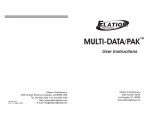
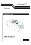
TRANSCENSION
Show Control
www.prolight.co.uk
DDP-405 Digital Dimmer Pack
(Order code: BOTE27)
User manual
Warnings
User manual
Warnings
IMPORTANT:
The manufacturer will not accept liability for any resulting damages caused
by the non-observance of this manual or any unauthorised modification to the
equipment.
• Never let the power-cable come into contact with other cables. Handle the
power-cable and all mains voltage connections with particular caution!
• Never remove warning or informative labels from the equipment.
• Do not open the equipment and do not modify the equipment.
• Do not switch the equipment on and off in short intervals, as this will reduce the
system’s life.
• Only use the equipment indoors.
• Do not expose to flammable sources, liquids or gases.
• Always disconnect the power from the mains when equipment is not in use or before
cleaning! Only handle the power-cable by the plug. Never pull out the plug by pulling the power-cable.
• Make sure that the available voltage is between 220v/240v.
• Make sure that the power-cable is never crimped or damaged. Check the equipment and the power-cable periodically.
• If the equipment is dropped or damaged, disconnect the mains power
supply immediately.
Have a qualified engineer inspect the equipment before operating again.
• If the equipment has been exposed to drastic temperature fluctuation (e.g. after
transportation), do not switch it on immediately. The arising condensation might
damage the equipment. Leave the equipment switched off until it has reached room temperature.
• If your product fails to function correctly, discontinue use immediately. Pack the unit
securely (preferably in the original packing material), and return it to your Prolight dealer for service.
• Only use fuses of same type and rating.
• Repairs, servicing and power connection must only be carried out by a qualified
technician. THIS UNIT CONTAINS NO USER SERVICEABLE PARTS.
• WARRANTY; One year from date of purchase.
OPERATING DETERMINATIONS
If this equipment is operated in any other way, than those described in this manual,
the product may suffer damage and the warranty becomes void.
Incorrect operation may lead to danger e.g.: short-circuit, burns, electric shocks,
lamp failure etc.
Do not endanger your own safety and the safety of others!
Incorrect installation or use can cause serious damage to people and property.
User manual
Functions and Controls
8
Rear View
FUSES: F6.3A 250V 5x20mm
1
2
3
DMX IN
3
4
1
This product must not be
continuously used for
a long time under 20A
total output load
DMX OUT
3
2
2
1
WARNING:
THIS APPARATUS MUST
BE EARTHED N’OUVREZ
PAS.. RISQUE DE
CHOCELECTRIQUE
9
POWER
POWER INPUT:AC 220V~50HZ
Front Panel
10
11
5
TRANSCENSION
Show Control
6
7
1
2
3
12
1. Mode Button
2. Menu Button
3. Up button
4. Down Button
5. Output Sockets
6. LED Indicators
7. LCD Display
8. Channel Fuses
9. Power Switch
10. Power Cord
11. DMX Input
12. DMX Output
4
User manual
Overview Functions
Mode Button: This button will switch the unit between DMX mode and Chase mode.
Menu Button: This button will activate different functions in DMX mode or Chase mode.
Up Button: This button will increase the displayed value in the LCD display.
Down Button: This button will decrease the displayed value in the LCD display.
Output Sockets: These 8 IEC sockets are used to power the equipment.
LED Indicators: These LED indicators will illuminate when the corresponding channel
is activated.
Channel fuses: Each of the four channels is protected by a 6.3A fuse. These fuses prevent the unit from overloading and being damaged. Be sure to
always replace them with the exact same type fuses.
Power Switch: This switch controls the unit’s main power.
Power Cable: Plug this cable into a rated main power supply for your area.
DMX Input: This connector allows the input of a DMX control signal.
DMX Output: This connector allows the output of a DMX control signal to the
next device.
Operation
The unit has two switchable working modes. It can be used as a four channel chaser or as
a 1, 2, or 4 channel DMX dimmer pack. Please follow up the instructions below to operate
the unit for your desired performance.
Chase Mode
Choose this working mode only when you want the device to act as a 4-channel chaser.
This device has 16 built-in programmes. You can select to run any of these programmes
specifically, or set the unit to chase in a random sequence among all 16 built-in
programmes for a more dramatic show effect. The chase speed can also be adjusted.
1) Connect your lighting effects to any of the 8 IEC sockets on the pack.
2) Use the “MODE” button to select Chase mode: Chase mode is indicated in the LCD
display as “PA” followed by numbers 01-16.
“PA” stands for “PROGRAMME APPLIED”.
If an “A” appears in the LCD display, it means you are in DMX mode,
“A” stands for “ADDRESS”.
3) Set your desired chase pattern: Once you have selected the chase function, use the
“MENU” button to select your desired chase. The chase pattern is represented in the
LCD display by “P” followed by two numbers. You may select any of the 16 built-in
programmes to run at a single time.
User manual
Chase Mode (cont)
4) Set your desired chase speed: At this point you may change the programme chase
speed. While in chase mode, tap on the “MENU” button until the “SP” followed by two
numbers is displayed in the LCD display. Then use the and buttons to adjust the
chase speed. A value of 99 will give you the fastest chase speed
(about one step per 0.1 of a second). The value of 01 will give you the slowest chase
speed (One step per 30 seconds)
5) You may now change the light intensity: Use the “MENU” button to select “d” on the
LCD display. Use the and buttons to change the light output intensity.
(00 = lowest output and 99 = highest light output).
DMX Mode
Use this operating mode only if you plan to use your pack as a DMX dimmer.
This function will allow you to turn on and control the intensity of non-DMX fixtures e.g. par
cans and pinspots with the use of a DMX controller. On, Off and dimming functions can be
perfomed through this pack. You may also set your dimmer pack to function as a 1, 2, or 4
channel DMX dimmer pack, which means you can combine the output functions.
DMX Operation
1) Connect a DMX controller to your dimmer pack via the 3-pin XLR connector.
2) Connect your lighting effect to any of the 8 IEC sockets on the front of
the pack.
3) Decide if you are going to use your dimmer pack as 1, 2, or 4 channels. This function
allows you to:
a) Control the output of all 8 outlets with one DMX channel.
b) Group outlet channels one and two and group outlet channels 3 and 4.
The first group will be controlled by one DMX channel and the second group will be controlled by another DMX channel. This gives the pack a DMX value
of two.
c) The default setting is a four channel DMX dimmer, each channel is controlled by one DMX channel.
4) To change the channel function mode, be sure you are in DMX mode. Use the “MENU”
button to select “CH” followed by two digits. Then use the and buttons to change
the setting from 01, 02, or 04.
5) The dimmer pack is initially set to be activated by address one. To change this setting
be sure you are in DMX mode. Use the “MENU” button to select the address settings,
this will be indicated by an “A” in the first character of the LCD display followed by three
numbers. Use the and buttons to select your desired DMX address. Remember the
DMX address tells your DMX controller what channel to activate the pack’s functions.
6) Once you have set the pack’s DMX address, be sure that your controller’s address
matches that of the Pack’s.
User manual
Replacing a Fuse
7) Your pack will now operate as a DMX dimmer, you may control the light output intensity
through your DMX controller.
(0 will give no output and 100 will give you full light output.)
Replacing a fuse
To replace the protective fuse, use a flat head screw driver to unscrew the fuse holder.
Pull out the fuse. Insert a new and exact same type fuse back into the fuse holder and
tighten. Always replace with the exact same type fuse or other type approved by our
authorized service technician.
CAUTION: Always disconnect the units main power before performing any type of
service or fuse replacement!!
Power Supply
Before plugging your unit in please make sure the source voltage in your area matches
the required voltage for you device. Because line voltage may vary from venue to venue,
you should be sure to plug your power supply into a matching wall outlet before
attempting to operate your device.
Product Description
This unit is a 1, 2, or 4 channel DMX dimmer pack. This pack can serve as a stand-alone
chaser or a DMX dimmer pack. Each channel is assigned with two parallel output sockets
for total of eight. This unit features XLR female and male connectors for DMX connection.
Each channel is equipped with a 6.3A fuse, And a maximum output load of 5A per
channel or 16A totally.
Technical Data
Item Name...............................................................................................................MPX-405
Power Supply...............................................................................................AC 240V ~ 50Hz
Dimensions..................................................................................................260 x 190 x 75mm
Weight....................................................................................................................2.7Kgs
Fuse............................................................................................F6.3A 250V 5 x 20mm, 4pcs
User manual
TRANSCENSION
Show Control
www.prolight.co.uk
User manual