1
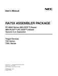
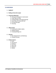
M u l t i f u n ct i on D a t a
Ac qu i si t i on P C B oa r d
AD 2 5 P C I
© XII. 2007 Arepoc s.r.o.
Multifunction DAQ Board
AD25PCI
AREPOC s.r.o. Company would like to thank you for purchasing the
Multifunction Data Acquisition PC Board AD25PCI. We believe it
will meet your expectations.
In case you need any assistance, please do not hesitate to contact us:
Address:
AREPOC s.r.o.
ILJUSINOVA 4
851 01 BRATISLAVA
SLOVAKIA
Phone/Fax:
E-mail:
+421 2 6382 4613
[email protected]
Product No.:
2
M U L T I F U N C T I O N DAQ B O A R D AD25PCI
The AD25PCI Analog and Digital I/O Board is specially designed
for applications that need a programmable DC current source and
precise differential analog inputs. The board in combination with
PciDAQ software and AREPOC Hall probes is also ideal suited for
high-resolution magnetic field measurements.
Following are the system requirements for installing the card and
accompanying Windows ™ software.
• Pentium class computer with a free PCI-5V (32-bit) slot
• Windows 98/NT/2000/XP operating system
Unpacking
The data acquisition board package includes the following:
• Multifunction AD25PCI Board
• Technical Products CD-ROM with drivers and manuals
• Printed version of the AD25PCI manual
• CANNON 25-pin male connector with 10 Ohm resistor connected
to the current source (pins 14, 1) and input Channel 0 (pins 5, 17).
!
Electrostatic discharge can damage several components on the
board. To avoid such damage in handling the board, take the
following precautions:
• Ground yourself by a grounding strap or by holding a grounded
object.
• Touch the antistatic package to a metal part of your computer
chassis before removing the board from the package.
• Remove the board from the package and inspect the board for
loose components or any other sign of damage. Notify AREPOC
if the board appears damaged in any way. Do not install a
damaged board into your computer.
• Never touch the exposed pins of connectors and PCI bus.
Place the board in front of you as you go through the next chapter.
This will help you to identify the components on the board.
3
M U L T I F U N C T I O N DAQ B O A R D AD25PCI
Functional Description
The conception of this high performance PCI-bus analog and digital
I/O board differs from other data acquisition boards and approaches
rather higher accuracy multimeters. Major component of this
multifunction plug-in board consists of a single-chip microcomputer,
which controls all functions of the board. The board consists of an
isolated high resolution integrating AD converter with 8 differential
inputs, programmable non-isolated current source and digital
inputs/outputs.
Board configuration
Digital I/O
connector
J3, J4
jumpers
CANNON 25
I/O connector
The AD25PCI board contains 3 jumpers to configure I/O settings.
Jumper J2 is for unipolar or bipolar analog inputs selection. Jumpers
J3, J4 are for +15V and –15V output voltage selection.
J2 jumper
Fig. 1. The J2, J3 and J4 jumpers and I/O connectors locations.
4
M U L T I F U N C T I O N DAQ B O A R D AD25PCI
Analog Inputs Settings
The AD25PCI differential analog inputs are configurable for bipolar
or unipolar input ranges. Unipolar input means that the input voltage
range is between 0 and Vref where Vref is a positive reference voltage.
Bipolar input means that the input voltage range is between -Vref/2
and +Vref/2. Following table shows the configuration of the J2
jumper settings.
Configuration
Bipolar ±5 V (factory setting)
Unipolar 0 to +10 V
J2
J2
J2 Jumper Settings
OPEN
CLOSE
Analog Inputs
The analog inputs have software-programmable gains of 1 to 128
allowing analog input ranges from ±39 mV to ±5 V in bipolar mode,
respectively from +78 mV to +10 V in unipolar mode. Amplified
voltages are multiplexed into an analog-to-digital converter operating
on the principle of modified sigma-delta modulation of charge
balancing.
The table shows actual unipolar and bipolar input ranges.
Gain
Unipolar Input Range
Bipolar Input Range
1
2
4
8
16
32
64
128
0 to +10 V
0 to +5.0 V
0 to +2.5 V
0 to +1.25 V
0 to +0.62 V
0 to +0.31 V
0 to +0.16 V
0 to +78 mV
±5.0 V
±2.5 V
±1.25 V
±0.62 V
±0.31 V
±0.16 V
±78 mV
±39 mV
5
M U L T I F U N C T I O N DAQ B O A R D AD25PCI
Integration time of analog inputs is software-programmable from 5 to
320 ms in four steps with corresponding resolution from 20 to 26
bits. Real resolution is limited by noise of the AD converter. For low
gains (1x, 2x and 4x) the noise is limited by the AD converter itself
and the achievable resolution is approx. 17, 18, 19, 20 bits for
integration time 5, 20, 80, 320 ms. Conversion time of each channel
for data processing versus effective analog input resolution is shown in
the table:
Resolution [bit]
20
22
24
26
Effective resolution [bit]
Integration time [ms]
Conversion time [ms]
17
5
13
18
20
28
19
80
88
20
320
328
For higher gains the resolution is limited by noise of the input
amplifier, which is approximately 400 nVp-p for integration time 320
ms and raises up to approx. 700 nVp-p for 20 ms integration time.
Corresponding resolution for gain 128 (range 0 - 78 mV) is 17.5 bits
for integration time 320 ms.
Integration principle of conversion and isolation guarantees higher
immunity against spurious voltages. In order to obtain total
conversion time, 5 to 25 ms must be added (depends on a PC
performance) for data processing. To reach high accuracy and
stability, the board is equipped with auto-calibration function, which
enables to eliminate board’s offset and calibrate the range of the
converter by means of a highly stable calibration source of 5 V.
Current Source
The AD25PCI board provides a programmable non-isolated unipolar
DC current source. The output current can be software-configured in
the range of 0 to 20 mA (0 – 100 mA optional) with 14-bits output
resolution. Analog output is connected to pin 14 (OUT CURRENT)
and pin 1 (PCGND) of the CANNON 25 I/O connector. It is possible
to turn off the current source from application software environment.
The cut-off current in the turn-off state is lower than 1 μA.
6
M U L T I F U N C T I O N DAQ B O A R D AD25PCI
Power Connections
Pins 2 (+15Vout) and 15 (-15Vout) of the I/O connector supply voltage
from a PC power supply. These +15V and -15V voltages are
referenced to the floating ground (AGND pins 3, 4, 13 or 25) and are
available to power external accessories or circuitry. Maximum power
rating is 20 mA. To enable these voltage outputs close the J3 (+15V)
and/or J4 (–15V) jumpers.
Configuration
+15 V disabled
-15 V disabled
+15 V enabled
-15 V enabled
+15 V enabled
-15 V disabled
+15 V disabled
-15 V enabled
J3, J4 Jumper Settings
J3
J4
J3
J4
J3
J4
J3
J4
OPEN (factory setting)
OPEN (factory setting)
CLOSE
CLOSE
CLOSE
OPEN
OPEN
CLOSE
careful to use the +15V and -15V power outputs! Shorting
! Beor grounding
these outputs (pin 2 and/or pin 15) of the analog I/O
out
out
connector can damage the board or PC motherboard! AREPOC is not
liable for damages resulting from such a connection.
Digital Inputs and Outputs
The AD25PCI provides 8 digital I/O lines TTL/HCT compatible. A
strobe signal is provided for latching the digital input/output signals
into external circuitry. Digital I/O lines are programmable using
DigIn and DigOut functions of the Ad25plib.dll library. Voltages
+5V DC and +12V DC are referenced to DIGGND pins of the digital
connector and are available to power external accessories.
careful to use +5V and +12V power outputs! These voltage
! Becircuits
are NOT ISOLATED from the PC and are connected
directly to the PCI bus! Shorting or grounding pin 19 and/or pin 20
of the digital I/O connector can damage the board or PC
motherboard! AREPOC is not liable for damages resulting from such
a connection.
7
M U L T I F U N C T I O N DAQ B O A R D AD25PCI
Hardware Installation
After you have correctly set and verified the J2 - J4 jumpers, you are
ready to install the board into your computer. The AD25PCI
multifunction board can be installed in any available PCI-5V (32-bit)
expansion slot in the computer. To achieve the best noise
performance it is recommended to leave as much room as possible
between the AD25PCI device and other devices installed in your PC.
The following are general installation instructions. Consult your PC
user manual or technical reference manual for specific instructions
and warnings.
1.
2.
3.
4.
5.
6.
7.
8.
9.
Turn off your computer and all peripheral devices. Unplug the
power cord from the wall outlet.
Remove the cover from your computer.
Find a free PCI -5V expansion slot in your system.
Remove the metal plate from the slot you have chosen and put
the screw aside.
Ground yourself and discharge any static electricity.
Insert the AD25PCI board into the PCI slot. It may be a tight fit,
but do not force the board into place.
Secure the board to the slot with the screw you removed from
the metal plate.
Check the installation.
Replace the cover of your computer.
The AD25PCI multifunction board is installed. You are now ready to
install and configure your software.
Changing the Board Settings
Before changing the hardware settings of your board (J2, J3 and J4
jumper settings) you must to turn off and unplug the computer.
8
M U L T I F U N C T I O N DAQ B O A R D AD25PCI
Driver Installation
The AD25PCI board is a Plug & Play component. The board
requests an IRQ number via its PCI controller. The system BIOS
responds with an interrupt assignment based on the card information
and on known system parameters. Because configuration is
controlled by the system and software, there is no jumper setting
required for the base-address, DMA, and interrupt IRQ. These
system parameters are determined by the driver which must be
installed in your system.
The board is supplied with a CD-ROM containing the driver and
software package for Windows NT 4.0 and Windows 98/2000/XP.
user with Administrator privileges must install this driver.
! APlease
consult your system administrator or Microsoft operating
system User’s Manual for more information on Administrator
privileges. The recommended installation steps are given below:
1. After installing your AD25PCI DAQ card, start up Windows. The
Found New Hardware Wizard appears. Check Search for a
suitable driver for my device and then click on Next button.
9
M U L T I F U N C T I O N DAQ B O A R D AD25PCI
2. Check the CD-ROM drives option and insert the CD into the
CD-ROM drive. Then click the Next button.
3. Wait for a moment while the operating system searches for the
most suitable driver to install, and you will finally see the
following window:
The Ad25pci.inf file is stored in <CD>:\INF directory.
10
M U L T I F U N C T I O N DAQ B O A R D AD25PCI
4. Click Next button and the operating system will begin to install
the driver. Follow instructions that appear on your screen. If the
Digital Signature Not Found box or Has Not Passed Windows
Logo Testing box appears, click Yes or Continue anyway.
5. After completion click Finish button to finish the installation
procedure. If the Restart dialog appears, then click Yes to reboot.
If your system doesn’t boot or if you experience erratic operation
with your PCI board, it’s likely caused by an interrupt conflict
(perhaps the BIOS Setup is incorrectly configured). In general, the
solution, once you determine it is not a simple oversight, is to consult
the BIOS documentation that comes with your system*. When done
with the driver installation the device manager can be open to make
sure the installation was a success. If your card has been properly
installed, you should see the device name of your AD25PCI board
listed on the Device Manager tab on the System Property page.
* Sporadic, some computers with Windows’XP operating system require to have installed the
DRVXWDM.SYS (or DRIVERX.SYS, DRIVERX.VXD) file in “<Windows>\System32\drivers”
directory. If the AD25PCI board does not operate correctly after rebooting PC, copy the required file(s)
from INF directory located on the installation CD to the “<Windows>\System32\drivers” directory.
11
M U L T I F U N C T I O N DAQ B O A R D AD25PCI
Now the first part of your installation has been completed and ready
to install supporting software for the board or write your own
application.
For the supporting software installation (e.g. PciDAQ software)
follow instruction given by the software installation wizard.
For customers who are writing their own applications, we provide
function 32-bit ad25plib.dll library compatible for Windows
98/NT/2000/XP operating systems. The ad25plib.dll and Drvx40.dll
libraries must be copied to a folder where an application will be
located. Both DLLs are stored on the Arepoc Technical Products
CD-ROM supplied with the board in the <CD>:\INF directory.
The developing environment can
Delphi, C++ Builder, LabVIEW,
language that allows calls to a
description of the ad25plib.dll is
manual.
12
be Visual Basic, Visual C++,
or any Windows programming
DLL. The function reference
located on the page 19 of this
M U L T I F U N C T I O N DAQ B O A R D AD25PCI
Analog I/O Connector
Figure 2 shows the pin assignments of the AD25PCI analog I/O
connector. The connector is located on the back panel of the board
and is accessible at the rear of the computer. The analog I/O
connector is a CANNON 25-pin female connector.
PC GND
+15Vout
(1 – 14) Current output
1
14
OUT CURRENT
15
-15Vout
(2) +15 VDC Source
(15) -15 VDC Source
16
Rs
(16) Reserved
17
0 IN Hi
(5 – 17) Input channel 0
18
1 IN Hi
(6 – 18) Input channel 1
19
2 IN Hi
(7 – 19) Input channel 2
20
3 IN Hi
(8 – 20) Input channel 3
21
4 IN Hi
(9 – 21) Input channel 4
22
5 IN Hi
(10 – 22) Input channel 5
23
6 IN Hi
(11 – 23) Input channel 6
24
7 IN Hi
(12 – 24) Input channel 7
25
AGND
2
AGND
3
AGND
4
0 IN Lo
5
1 IN Lo
6
2 IN Lo
7
3 IN Lo
8
4 IN Lo
9
5 IN Lo
10
6 IN Lo
11
7 IN Lo
12
AGND
13
(3, 4, 13, 25) Floating ground
Fig. 2. Pin assignments of the analog I/O connector
The floating ground (AGND) must be connected either to a Lo pin or
to the PC GND pin (recommended to use with Hall probes).
13
M U L T I F U N C T I O N DAQ B O A R D AD25PCI
Digital I/O connector
Figure shows the pin assignments for the AD25PCI digital I/O
connector. The connector is located on the board and is accessible
after removing the cover from your computer. Before connecting or
disconnecting to the digital I/O connector you must turn off and
unplug the computer.
IN 0
IN 2
IN 4
IN 6
OUT 0
OUT 2
OUT 4
OUT 6
DIGGND
PC +5V
1
3
5
7
9
11
13
15
17
19
2
4
6
8
10
12
14
16
18
20
IN 1
IN 3
IN 5
IN 7
OUT 1
OUT 3
OUT 5
OUT 7
DIGGND
PC +12v
The following specifications apply to the digital I/O lines. Absolute
max. voltage input rating 5.0 V with respect to DIGGND.
Digital input specifications (referenced to DIGGND):
• VIH input logic high voltage 2 V min.
• VIL input logic low voltage 0.8 V max.
• IIH input current load, logic high input voltage 20 μA max.
• IIL input current load, logic low input voltage -20 μA max.
Digital output specifications (referenced to DIGGND):
• VOH output logic high voltage 2.4 V min.
• VOL output logic low voltage 0.5 V max.
• IOH output source current, logic high 2.6 mA max.
• IOH output sink current, logic low 24 mA max.
!
Maximum ratings are absolute ratings. Connections that exceed
any of the max. ratings of input or output signals on the AD25PCI
can damage the DAQ board and/or the PC AT. Arepoc is NOT liable
for any damages resulting from incorrect signal connections.
14
M U L T I F U N C T I O N DAQ B O A R D AD25PCI
Cabling and Wiring Consideration
Environmental noise can affect the accuracy of measurements made
with the AD25PCI if you do not make proper considerations when
running signal wires between signal sources and the AD25PCI board.
The following recommendations mainly apply to analog input signal
routing to the bard, although they are applicable for signal routing in
general.
Use individually shielded twisted-pair wires to connect analog input
signals to the AD25PCI. With this type of wire, the signals attached
to the Channel 0 - 7 inputs are twisted together and then covered
with a shield. This shield is then connected at only one point to the
signal source ground. This kind of connection is required for signals
traveling through areas with large magnetic fields or high
electromagnetic interference. To protect the signal lines from
magnetic fields caused by electric motors, welding equipment,
breakers or transformers, run the signal lines through special metal
conduits. In making your own cabling, you may decide to shield your
cables. The mating connector for the AD25PCI analog I/O is a
CANNON 25-position female connector.
Basically, the Lo input has to be connected to AGND when you are
measuring a floating signal. To measure voltages from several RTDs
which are biased from the board’s current source, you have to
connect the AGND to the PC GND pins (see Fig. 3).
14 [OUT Current]
5 [0 IN Hi]
RTD0
17 [0 IN Lo]
6 [1 IN Hi]
RTD1
18 [1 IN Lo]
1 [PC GND]
13 [AGND]
Fig. 3. Connecting to RTDs configuration
15
AD25PCI
M U L T I F U N C T I O N DAQ B O A R D AD25PCI
If you are measuring voltages from RTDs which are biased from an
external current source, you have to connect the AGND to the GND
of this current source (on one side only).
14 [OUT Current]
HP0
5 [0 IN Hi]
17 [0 IN Lo]
HP1
6 [1 IN Hi]
AD25PCI
18 [1 IN Lo]
1 [PC GND]
13 [AGND]
Fig. 4. Connecting to Hall probes configuration
Figure 4 shows how to connect two Hall probes to the AD25PCI
board. It is possible to connect max. 8 Hall probes to the board.
5 [0 IN Hi]
VDC
=
17 [0 IN Lo]
3 [AGND]
VAC
AD25PCI
6 [1 IN Hi]
~
18 [1 IN Lo]
4 [AGND]
1 [PC GND]
Fig. 5. Connecting to floating voltage configuration
Figure 5 shows how to connect DC and/or AC floating signal sources
to the AD25PCI board.
The input voltage from the Lo input or Hi input should not exceed
the maximum input voltage (based on the board analog ground). If it
exceeds the maximum voltage, the board may be damaged.
16
M U L T I F U N C T I O N DAQ B O A R D AD25PCI
High resolution of the AD25PCI board results from the application
of auto-calibration method. The analog I/O board AD25PCI can be
used in applications where high accuracy, linearity and resolution are
required. It can serve as a relatively low cost substitution of 6-decade
system multimeter.
Technical Parameters:
Analog Inputs
Input resolution (programmable)
Nonlinearity (if gain =1)
Typical noise
20 to 26 bits
typ.: 0.0005 % of full scale
max.: 0.0008 %
max.: 1 LSB
0.005 % of reading
0.01 % of FS
8 differential
0 - 10 V unipolar or ± 5 V bipolar
(jumper selectable)
1 - 128 (software selectable)
> 100 MΩ
typical: 10 nA, max.: 50 nA
± 20V continues, powered
± 10V continues, unpowered
< 2 ppm of FS, or < 0.5 μVp-p
Current Source
Output current range
Output current resolution
Output current ripple
Cut-off current
Max. output voltage
0 - 20 mA (0 - 100 mA optional) DC
14 bits
< 0.0005 % of FS, or < 0.5 μA
< 1 μA
7.8 V
Power Connections
Floating output voltage
Max. power load
+15 V, -15 V (jumper selectable)
20 mA
Digital Inputs and Outputs
8 digital I/O
Recommended warm-up time
Relative humidity
TTL/HCT compatible
>15 min
10% to 90% noncondensing
Differential nonlinearity
Max. error
Number of analog inputs
Input range
Programmable gain
Input resistance
Input bias current
Input overvoltage
17
M U L T I F U N C T I O N DAQ B O A R D AD25PCI
Warranty
The AD25PCI multifunction board is warranted against defects in materials and workmanship for a
period of one year from the date of shipment, as evidenced by receipts or other documentation. Arepoc
will, at its option, repair or replace equipment that proves to be defective during the warranty period.
This warranty includes parts and labor. A Return Material Authorization number must be obtained from
the factory and clearly marked on the outside of the package before the board will be accepted for
warranty work. Arepoc believes that the information in this document is accurate. In the event that
technical or typographical errors exist, we reserve the right to make changes to subsequent editions of
this document without prior notice to holders of this edition. In no event shall Arepoc be liable for any
damages arising out of or related to this document or the information contained in it.
EXCEPT AS SPECIFIED HEREIN, AREPOC MAKES NO WARRANTIES, EXPRESS OR IMPLIED, AND
SPECIFICALLY DISCLAIMS ANY WARRANTY OF MERCHANTABILITY OR FITNESS FOR A
PARTICULAR PURPOSE. CUSTOMER’S RIGHT TO RECOVER DAMAGES CAUSED BY FAULT OR
NEGLIGENCE ON THE PART OF AREPOC SHALL BE LIMITED TO THE AMOUNT THERETOFORE PAID
BY THE CUSTOMER. AREPOC WILL NOT BE LIABLE FOR DAMAGES RESULTING FROM LOSS OF
DATA, PROFITS, USE OF PRODUCTS, OR INCIDENTAL OR CONSEQUENTIAL DAMAGES, EVEN IF
ADVISED OF THE POSSIBILITY THEREOF. This limitation of the liability of Arepoc will apply regardless
of the form of action, whether in contract or tort, including negligence. Any action against Arepoc must
be brought within one year after the cause of action accrues. Arepoc shall not be liable for any delay in
performance due to causes beyond its reasonable control. The warranty provided herein does not cover
damages, defects, malfunctions, or service failures caused by owner’s failure to follow the Arepoc
installation, operation, or maintenance instructions; owner’s modification of the product; owner’s abuse,
misuse, or negligent acts; and power failure or surges, fire, flood, accident, actions of third parties, or
other events outside reasonable control.
Warning Regarding Use of Arepoc Products
AREPOC PRODUCTS ARE NOT DESIGNED WITH COMPONENTS AND TESTING FOR A LEVEL OF
RELIABILITY SUITABLE FOR USE IN OR IN CONNECTION WITH SURGICAL IMPLANTS OR AS
CRITICAL COMPONENTS IN ANY LIFE SUPPORT SYSTEMS WHOSE FAILURE TO PERFORM CAN
REASONABLY BE EXPECTED TO CAUSE SIGNIFICANT INJURY TO A HUMAN.
IN ANY APPLICATION, INCLUDING THE ABOVE, RELIABILITY OF OPERATION OF THE SOFTWARE
PRODUCTS CAN BE IMPAIRED BY ADVERSE FACTORS, INCLUDING BUT NOT LIMITED TO
FLUCTUATIONS IN ELECTRICAL POWER SUPPLY, COMPUTER HARDWARE MALFUNCTIONS,
COMPUTER OPERATING SYSTEM SOFTWARE FITNESS, FITNESS OF COMPILERS AND DEVELOPMENT
SOFTWARE USED TO DEVELOP AN APPLICATION, INSTALLATION ERRORS, SOFTWARE AND
HARDWARE COMPATIBILITY PROBLEMS, MALFUNCTIONS OR FAILURES OF ELECTRONIC
MONITORING OR CONTROL DEVICES, TRANSIENT FAILURES OF ELECTRONIC SYSTEMS (HARDWARE
AND/OR SOFTWARE), UNANTICIPATED USES OR MISUSES, OR ERRORS ON THE PART OF THE USER
OR APPLICATIONS DESIGNER (ADVERSE FACTORS SUCH AS THESE ARE HEREAFTER COLLECTIVELY
TERMED “SYSTEM FAILURES”). ANY APPLICATION WHERE A SYSTEM FAILURE WOULD CREATE A
RISK OF HARM TO PROPERTY OR PERSONS (INCLUDING THE RISK OF BODILY INJURY AND DEATH)
SHOULD NOT BE RELIANT SOLELY UPON ONE FORM OF ELECTRONIC SYSTEM DUE TO THE RISK OF
SYSTEM FAILURE. TO AVOID DAMAGE, INJURY, OR DEATH, THE USER OR APPLICATION DESIGNER
MUST TAKE REASONABLY PRUDENT STEPS TO PROTECT AGAINST SYSTEM FAILURES, INCLUDING
BUT NOT LIMITED TO BACK-UP OR SHUT DOWN MECHANISMS. BECAUSE EACH END-USER SYSTEM
IS CUSTOMIZED AND DIFFERS FROM AREPOC’ TESTING PLATFORMS AND BECAUSE A USER OR
APPLICATION DESIGNER MAY USE AREPOC PRODUCTS IN COMBINATION WITH OTHER PRODUCTS
IN A MANNER NOT EVALUATED OR CONTEMPLATED BY AREPOC, THE USER OR APPLICATION
DESIGNER IS ULTIMATELY RESPONSIBLE FOR VERIFYING AND VALIDATING THE SUITABILITY OF
AREPOC PRODUCTS WHENEVER AREPOC PRODUCTS ARE INCORPORATED IN A SYSTEM OR
APPLICATION, INCLUDING, WITHOUT LIMITATION, THE APPROPRIATE DESIGN, PROCESS AND
SAFETY LEVEL OF SUCH SYSTEM OR APPLICATION.
18
M U L T I F U N C T I O N DAQ B O A R D AD25PCI
The AD25PCI comes with functions in Dynamic Link Library (DLL)
ad25plib.dll which can be called from VC++, Delphi, Visual Basic
or LabVIEW. The AD25PCI supports two modes of operation:
single conversion or periodical measurement.
In single conversion mode the AD25PCI takes one sample
immediately after calling function Adconv which returns measured
value. An advantage of this mode is a simple programming.
Disadvantage: triggering is derived from the PC so timing accuracy
can be lower.
In periodical mode measurement sequence is programmed first using
procedures ProgCh, ProgEn, Timer, etc. Advantage of this mode is
that triggering is controlled by internal clock of the AD25PCI and,
therefore, the triggering is more accurate (PC must only read-out
results before start of the next conversion). Disadvantage: during
periodical measurement the auto-calibration is inaccessible;
therefore, this mode is suitable for short-time measurement up to few
minutes only.
Description of the AD25PLIB.DLL library
Dynamic Link Library ad25plib.dll offers the following procedures
and functions:
function initAD:integer; stdcall; external 'ad25plib'
Initializes the AD25PCI. After successful initialization function returns 1,
otherwise returns 0. This function must be called first before any other
function.
procedure calibration(type, range, resol:integer); stdcall; external
'ad25plib'
This procedure accomplishes auto-calibration of the AD25PCI. Every used
range with common resolution must be calibrated before measurement!
Auto-calibration removes drift of the card so it is recommended to call this
routine during measurement in interval tens of seconds.
19
Parameters:
Type - 0 - calibrate only selected range (it is faster)
1 - calibrate all ranges (call only if use more ranges during
measurement)
range - 0..7 - select gain 1, 2, 4, 8, 16, 32, 64 or 128
resol - 0..3 - select integrating time 5, 20, 80 or 320 ms
function GetRange:integer; stdcall; external 'ad25plib'
This function return 1 if the card measures in unipolar mode, 0 in bipolar
mode. Mode selects jumper J2 on the board.
function Adconv(resol, range, chan:integer):single; stdcall; external
'ad25plib'
Immediately takes one measurement on selected input.
Parameters:
resol, range - the same as in the procedure calibration
chan - 0..7 - number of the measured channel
Returned value is measured voltage in volts.
procedure ProgEn(chan, resol:byte); stdcall; external 'ad25plib'
Sets number of measured channels and resolution in the periodical
measurement.
Parameters:
chan - number of measured channels
resol - see procedure calibration
procedure ProgCh(chan, range:byte); stdcall; external 'ad25plib'
Sets channel and range for every measured input.
Parameters - see function Adconv
procedure Timer(burst:byte; time:word); stdcall; external 'ad25plib'
Sets total measurement period in periodical measurement.
Parameters:
burst - always 1 - 2nd channel is measured immediately after the 1st, 3rd
channel after 2nd, etc.
time - total measurement period in ms, max. value is 9000. For proper
function time must be equal or bigger then the sum of conversion
time of all measured channels
20
procedure StartAD; stdcall; external 'ad25plib'
Starts measurement in periodical mode.
function GetSample(range:byte):single; stdcall; external 'ad25plib'
Read one sample in periodical mode.
Parameters:
range - see procedure calibration
function ADfinished:integer; stdcall; external 'ad25plib'
Returns 1 if measurement in periodical mode is finished, otherwise returns
0.
procedure StopAD; stdcall; external 'ad25plib'
Stops measurement in periodical mode.
procedure DAC(value:word); stdcall; external 'ad25plib'
Sets value of the current from the current source.
Parameters:
value - 0..4000 corresponds to current 0...20 mA i.e. 1 LSB is 0.005 mA
(optional to current 0…100 mA i.e. 1 LSB is 0.025 mA)
procedure DigOut(value:byte); stdcall; external 'ad25plib'
Writes value on a digital output.
function DigIn:byte; stdcall; external 'ad25plib'
Reads value from a digital input.
procedure closeAD; stdcall; external 'ad25plib'
Unload the driver from memory.
function GetCurrentRange:integer;stdcall; external 'ad25plib'
Returns max. current value of the current source (20 or 100) mA.
function GetDACresolution:integer;stdcall; external 'ad25plib'
Returns resolution of the DAC current source converter (14 bits).
function GetSerialN:integer;stdcall; external 'ad25plib'
Returns serial number of the DAQ board.
21
Programming Example
Here is a simple common example in Delphi which can be adapted to
any programming language.
Single conversion example:
if initAD = 0 then
//card initialization
begin
MessageBox(0, 'Unable to connect to AD25PCI', 'Error', MB_OK);
Exit;
end;
unip:= GetRange;
//read unip/bip range, unip=1-unipolar
resol:=2;
//Tint=80 ms; resolution cca 19 bits}
Calibration(0,0,resol);
//Calibration - only range ±5V
u:= ADConv(resol,0,1);
//channel 1, range ±5V
Periodical measurement example:
if initAD = 0 then
//card initialization
begin
MessageBox(0, 'Unable to connect to AD25PCI', 'Error', MB_OK);
Exit;
end;
unip:= GetRange;
//read unip/bip range, unip=1 - unipolar
resol:=2;
//Tint=80 ms; resolution cca 19 bits}
Calibration(1,0,resol);
//Calibration - all ranges
ProgEn(3,resol);
//Measure 3 channels
ProgCh(0,0);
//Input 0, range ±5V
ProgCh(1,2);
//Input 1, range ±1.25V}
ProgCh(2,1);
//Input 2, range ±2.5V}
Timer(1,1000);
//Burst mode, period 1000 ms}
StartAD;
for i:=1 to 5 do
begin
repeat until Adfinished=1;
//wait for end of the conversion
ux[0,i]:=GetSample(0);
//read input 0, range 0
ux[1,i]:=GetSample(2);
//Input 1, range 2
ux[2,i]:=GetSample(1);
//Input 2, range 1
end;
StopAD;
Setting current example:
DAC(2000);
//current 10 mA (for AD25PCI board with
the 20 mA current source)
22
Using the LabVIEW™
Procedures and functions of the ad25plib.dll can be called also from
the LabVIEW in Windows operating system. The calling convention
is stdcall; a simple example application can be found in the file
AD25PCI.vi stored on the Arepoc Technical Products CD-ROM
supplied with the board. Before the first run it is necessary to set
proper path to the ad25plib.dll. After loading the AD25PCI.vi
switch to the diagram, double click on every function and set proper
name and path to the library.
Note, that Driverx.sys must be installed in your …\System32\Drivers
directory and the Drvx40.dll must be installed in your application or
in the LabVIEW directory.
23
Information furnished is believed to be accurate and reliable. However, AREPOC s.r.o.
assumes no responsibility for the consequences of use of such information nor for any
infringement of patents or other rights of third parties, which may result from its use. Product
and company names are trademarks or trade names of their respective companies.
Specifications mentioned in this publication are subject to change without notice. This
publication supersedes and replaces all information previously supplied.
AREPOC s.r.o., Iljusinova 4, 851 01 Bratislava, SLOVAKIA
FAX: +421 2 6382 4613 E-mail: [email protected]
http://www.arepoc.sk
24