1
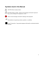
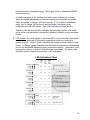
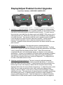
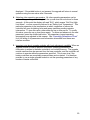
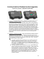
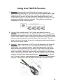
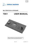
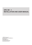
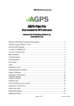
Series 48 Heater User’s Guide 1 For more information or literature, contact: MKS Instruments, Inc. 5330 Sterling Drive Boulder, CO 80301 USA Phone: Toll Free: Fax: Email: Web: 1-303-449-9861 1-800-345-1967 1-303-449-2003 [email protected] http://www.mksinst.com/vthome.html © 2006 by MKS Instruments, Inc. All rights reserved. 2 Table of Contents Package Contents . . . . . . Symbols Used in this Manual . . . . Safety Precautions . . . . . . Cleaning . . . . . . . . General Specifications . . . . . Examples of Applications for Series 48 Heaters . About the Series 48 Heater System . . . Installing Series 48 Heaters . . . . Controller Operations and Visual Signals (Base Model) LED Indications Chart . . . . . Display/Adjust Enabled Control Upgrades . . Operating Parameters Chart . . . . Communications Enabled Control Upgrades . Using LTA/HTA Function . . . . . Accessories/Part Replacement . . . . Troubleshooting . . . . . . Modbus Register Assignments . . . . Limited Product Warranty . . . . . . . . . . . . . . . . . . . . . . . 4 5 6 6 7 8 9 10 17 18 19 21 22 24 26 27 28 29 3 Package Contents Before unpacking your Series 48 heater system, check all surfaces of the packing material for shipping damage. Be sure that your Series 48 heater system contains these items: • Series 48 heaters as specified on packing slip, each equipped with a controller and coiled cable. If ordered, optional control expansion items will also be included with the heaters. • Flange insulators (if required). • Main power cable. • CE Declaration of Conformity. Inspect the components for visible evidence of damage during shipment. If anything has been damaged, notify the carrier immediately. Keep all shipping materials and packaging for claim verification. Do not return the product to MKS. If any items are missing from the package, call MKS/HPS Customer Service at 1303-449-9861 or 1-800-345-1967. MKS Instruments, Inc. 5330 Sterling Dr. Boulder, CO 80301 USA Telephone Toll-Free Facsimile (303) 449-9861 (800) 345-1967 (USA only) (303) 449-2003 4 Symbols Used in this Manual CAUTION: Risk of electrical shock. CAUTION: Refer to manual. Failure to heed message could result in personal injury, serious damage to the equipment, or both. Failure to heed message could result in damage to the equipment. Calls attention to important procedures, practices, or conditions. Class 2 Construction. Ungrounded equipment with double or reinforced electrical insulation. 5 Safety Precautions Do not use heaters outdoors or in an explosive environment. Electric shock or ignition of explosive vapors is possible. Heaters are designed for use with metal piping. Heater operating temperatures may exceed the melting point of other materials. Check specifications. Do not immerse the satellite controllers, cables, or heaters in water or liquid of any kind. Electrical shock may result. Permanent equipment damage may also occur. Ground piping system according to U.S. National Electric Code or local requirements or both. A Ground Fault Equipment Leakage Circuit Interrupter (GFELCI) should be used. Although grounded piping is not required, the performance of the GFELCI is enhanced and risk of electrical shock is further reduced when the piping is grounded. The heaters themselves are double-insulated devices and do not require a ground. Heaters must be secured to piping before operation. Heaters may overheat, resulting in permanent damage, if not attached to piping. Also, heaters should only be used on piping which matches a heater’s internal diameter and shape. Follow hazardous chemical safety procedures specified by the chemical supplier when heating vacuum piping designed to conduct hazardous chemicals. Cleaning Clean base station, satellite controllers, cables and heaters with damp cloth and mild detergent. Do not immerse in water. There is a risk of electrical shock and damage to the equipment. Do not use solvents. Some of the plastic enclosures may be attacked. 6 General Specifications Electrical rating Pollution Degree Over-voltage category 100 – 120 V~, 50/60 Hz, 10 A 200 – 240 V~, 50/60 Hz, 10 A 6% to 85% depending on temperature set point and supply voltage 1 II Environment Relative humidity Indoor use only 0% to 90 % non-condensing Pipeline temperature Heater exterior surface Adjustable 0-185°C, in 1 degree increments 0-80°C, depending on temperature set point Materials Heater: molded silicone foam, fiberglass-reinforced silicone fabric, Teflon® insulated wire Heater cable: polyurethane sheath, Teflon® insulated core wires Controller: polycarbonate enclosure Satellite controller: 0.05 kg Heater: 0.1 to 2.5 kg Electric duty cycle Weight Safety Agency Testing UL Listed File E52951 2JR 89/336/EEC EMC Directive 73/23/EEC LV Directive 7 Examples of Applications for Series 48 Heaters Semiconductor Industry Applications • Prevent solidification of ammonium chloride (NH4Cl) in a silicon nitride LPCVD system • Prevent solidification of aluminum chloride (AlCl3) in an aluminum etching system • Reduce solid buildup in other semiconductor processes, such as titanium nitride, tungsten, and TEOS CVD • Maintain uniform temperature environments in downstream semiconductor and related processes and equipment • Maintain gas temperature in gas delivery systems Biopharmaceutical Industry Applications • Prevent vapor condensation in sterile vent filters and piping systems • Maintain or promote preferred material viscosities Custom and R&D Applications • Heaters for custom and R&D applications can be engineered to meet specific requirements. Contact the MKS/HPS engineering group at 1-800-345-1967 for assistance. 8 About the Series 48 Heater System The Series 48 Heater System is an integrated, electronically controlled line of heater products. They have been designed to meet a variety of application requirements while emphasizing personnel safety and equipment preservation. These heaters reduce contamination; increase system uptime and product yield; and decrease scheduled maintenance. Series 48 heaters are designed to be easy to install, operate, and customize to meet the needs of modern manufacturing processes. By using an optional upgrade module, each of the controlling parameters of any heater can be individually adjusted for complete heating system customization and control. This will permit simple adjustments such as correcting a cold spot, creation of a thermal ramp across the entire system, or anything in between. Control settings can be modified “on the fly” without the need to interrupt power to the system. The system can be operated and controlled locally, remotely, or both can be done simultaneously. Optional upgrade modules allow for RS485 communications and remote connectivity via Internet. User-friendly software has been created to allow the adjustment of any of the control parameters, data logging, and heater diagnostics. It has the ability to automatically assign individual addresses to each controller. It is therefore not necessary to manually assign an address to each controller prior to installation, although this can be done if desired. Controlling devices such as thermostats, switches, and fuses, are subject to premature degradation and failure due to exposure to high temperatures. They are typically installed within the heater in close proximity to that which is being heated, resulting in component degradation and premature failure. These devices do not exist in Series 48 heaters. All controlling and safety functions are located within the control housing. This ensures that the user can expect the longest possible lifetime from a heater. Over-temperature protection is performed within the controller; the limit temperature is user adjustable and the circuit re-settable. In case of an overtemperature event, the heater is not rendered useless. The operator simply re-sets the heater control and normal operation resumes. The molded silicone foam thermal insulation prevents heat loss and maintains the external temperature within safe limits while the internal temperature is as high as 185°C. From room temperature, the heaters typically reach their set temperatures in less than 30 minutes. All materials used in the heaters and insulators are suitable for clean room use. Based on Class 1 clean room tests conducted at HPS, Series 48 heaters emit less than ten 0.7µ particles per cubic foot per minute. 9 Installing Series 48 Heaters 1. Installation Overview 1.1. Inspect pipe system and heaters. 1.2. Install heaters 1.3. Install heater controllers 1.4. Daisy chain heater controllers using jumper cables provided. 1.5. Install optional control upgrade modules (if applicable). 1.6. Install RS485 communication cables (if applicable). 1.7. Apply power to heaters. 10 2. Detailed Installation Instructions 2.1. Inspect system and heaters for damage. Make sure that there are no burrs or other protrusions on components to be heated that could cut the heater and expose a live heater element wire. 2.2. Install the heaters on the system. Make sure to match the heater to the part being heated. These are molded heaters specifically designed to heat components of matching dimensions. In addition to diameter and length, it is also important to match other component features such as bend radius and bend angle. The fit should be snug to ensure good thermal contact between the heater and the part to be heated. Only moderate insulation compression is needed. Do not use any other device to hold a heater in place. 11 Heaters for bellows and flexible hose are designed for a loose fit to allow for modest bellows and hose movement. These heaters must be installed with the heater’s lead exit in the up position with respect to gravity. Failure to follow this instruction could lead to overheating and possible heater damage. Wrap and secure insulators around flanges. Correctly sized flange insulators must be used for bellows or hose installation. Special flange insulators are available for covering connections from tubing to hose. 2.3. Install the heater controllers onto the heaters. Notice that each of the controllers contains a white power receptacle on its right end, and black power receptacle on its top side. Controller Receptacles The white plug installed on the heater’s lead wire mates with the white receptacle of the heater controller as shown below. (The connectors & receptacles are keyed, so an improper connection is not possible.) Installing controllers 12 2.4. Daisy chain heater controllers using jumper cables provided. Starting at the last heater controller (with respect to power), insert the black eight-position connector of the terminating cable into the controller’s black eight-position receptacle as shown below. It will click into place. Terminating cable Installing cables into controllers Next, connect the white six-position connector of the terminating cable to the mating white six-position connector of the upstream tee cable: Tee Cable Connecting power cables Use only factory-supplied cables. Failure to do so may result in heater or controller damage or failure. 13 Now insert the tee cable’s black connector into the upstream heater controller’s black receptacle. Repeat this process for all heaters until the connection of the first heater controller is completed. Completed basic installation Please read sections 2.5 & 2.6 (control upgrade options), if they apply. If control upgrade modules are not to be used, proceed to section 2.7. 2.5. Install optional control upgrade modules. Control upgrade modules, if required, can be installed at any time (See “Control Upgrades” sections for more information). There are three types of upgrades available: Display/Adjust; Communication; and Display/Adjust/Communication. To install an upgrade, use a coin or appropriate tool to remove the standard cover plate attached to the base control unit. (Retain this cover plate if it needs to be re-installed at a later time.) The control upgrade module is simply snapped into the place from which the cover plate was removed, as shown below. Be sure to install control upgrades in a careful manner, aligning the module’s retention tabs with their respective holes in the base. Snap into place by applying pressure evenly across the face of the upgrade. 14 2.6. If required, install RS485 communication cables. Install appropriately equipped control upgrade modules as described above (2.5). Data cables are equipped with 6-position, 4-conductor RJ11 connectors. (Note: These are not standard telephone cables!) Notice that there are 2 receptacles for data cables on each module. Using a data cable of appropriate length, install one end of the cable into either communications port on the control assembly of the first heater, and the second end into either communications port of the control assembly of the second heater. Communications cable installation Using another cable, install one end into the remaining communications port of the second heater’s control, and the other end into either communications port of the third heater’s control. Repeat this process until the last heater’s controller has a single communications port occupied. At this point, a data cable extending from the heater system to a remote monitoring location (such as a laptop or PC) can be installed. The cable can be installed into either the available communication port of the first heater, or the available port of the last heater. It may be necessary to use an RS232RS485 converter for computer interface. This is available from MKS/HPS. 15 2.7. Apply power to the heaters. At this point, the heater assembly is completed and the system is ready to be connected to the electrical supply. Using the main power cable specifically designed for use with 48-Series heaters, mate the cable’s six-position electrical connector with its counterpart on the jumper cable inserted in the first controller. Included with most power cables and extending from the rear of the six-position connector are three wires: one 16GA green wire terminating with a ring; and two 22GA white wires terminating with small connectors. The green wire is used for grounding the equipment on which the heaters are installed, while the white wires are used for an optional Low Temperature Alert / High Temperature Alert (HTA/LTA) circuit. For instructions regarding the use of these wires, see “Using the LTA/HTA Function”. Once all of the electrical connections have been made, the power cable can be connected to the power supply. The heaters will begin operating within their programmed parameters. Ground piping system according to U.S. National Electric Code (NEC), local requirements, or both. Tee and Terminating Cable information: “Tee” Cables: Easily identifiable due to its T shape and three electrical connectors (2 six-position, 1 eight-position). It is to be used, with respect to power, on the first and any intermediate heater assembly in a group of assemblies. (A heater assembly is defined as a heater, a controller, a cable, and if it exists, an optional control upgrade.) “Terminating” Cables: Identifiable as a cable with 2 electrical connectors (1 six-position, 1 eight-position). It is to be used, with respect to power, on the last (or only) heater in a group of heater assemblies. This cable defines the end of an electrical chain from a single power source. Its main purpose is to close the LTA/HTA circuit. Lengths: Each of the above cables is available in two different lengths. A short cable will contain about three circular convolutions per six-position connector, and should be used on heaters of up to 12” in length. A long cable will contain about 11 circular convolutions per six-position connector, and should be used on heaters greater than 12” in length. 16 Controller Operations and Visual Signals Base Model, #4800-1150 1. Control Structure: The Series-48 heater control unit contains two microprocessors. One is dedicated to controlling and operation of the heater within specified (modifiable – see “Control Upgrades” sections) parameters, while the other is dedicated to safety. The control circuitry and safety circuitry operate independently of each other, with the exception of comparing data to ensure that both circuits are operating normally. Any discrepancies outside of pre-determined tolerance will cause an automatic heater shutdown. The main purpose of the safety circuitry is protection from an over-temperature event. If an unlikely malfunction were to occur and cause an overheating condition, the safety circuit will interrupt the power to the heater element via latching relay. This relay will remain open until power to the heater is cycled (turned off and on) and conditions are such that the latching relay should be closed once again. It is important to note that conditions external of the heater and controller are the usual cause of such an event (i.e. high temperature purge, cleaning cycle, etc.). Each microprocessor has its own temperature sensor dedicated to it (two thermocouples embedded within the heater), and therefore the controlling circuits are completely independent and redundant. 2. HTA/LTA alert function: The High Temperature Alert/Low Temperature Alert function provide both a local and remote notification that a heater is outside an acceptable operating temperature window about the set point. Both the HTA and the LTA values are independently adjustable, and are set as incremental values to be computed from the set point temperature. Default settings are: HTA = 20; LTA = 20. This means if the set point temperature is 150°C, the acceptable operating range will be 130°C – 170°C. Remote notification originates as an electrical signal from an external source (see ”Using the LTA/HTA Function”). If the heater’s temperature is determined by the control microprocessor to be within this operating range, a mechanical relay is then closed allowing the electrical signal to pass thru the relay and onto the next controller. When all heaters of the system are within the operating ranges determined by their controllers, all such relays are closed, completing the signal circuit. An external monitoring device, such as an LTA monitor, can then output a signal that all 17 heaters are within acceptable range. (This signal circuit is independent RS485 communications.) A visual local signal is also produced on each heater controller’s front panel. When a controller determines its heater’s temperature to be within acceptable range, the amber “In Range” LED will illuminate. If it is outside of acceptable range, the “In Range” LED will be off and the heater’s condition can be interpreted from the LED signals. (See “LED Indications Chart” below.) Therefore, the remote notification indicates the operating condition of a heater group, while local notification indicates the operating condition of each individual heater. 3. LED Signals: The visual signals of the three LED’s on the controller’s front panel can convey a great deal of information regarding a heater’s or controller’s operating status. “Output” (green) indicates that voltage is being supplied to the heater. “In Range” (amber) indicates that the heater’s temperature is determined to be in the acceptable operating range (as described above). “Alert/Alarm” (red) indicates that there is a condition that should be investigated. The below chart should be used to interpret the controller’s LED indications. LED Indications Chart 18 Display/Adjust Enabled Control Upgrades Local User Interface - #4800-0001 & #4800-0003 1. Installation of upgrade modules: A control module upgrade is a “plug-and-play” device. Installation and/or removal of upgrade modules can be performed at any time without interrupting power or heater/controller function. To install, remove the protective cover plate from the base control unit (#4800-1150) using a coin or other appropriate tool. Retain this cover plate for re-installation if the upgrade is to be later removed. Then simply install the control upgrade module by snapping it into the place from which the cover plate was removed. A small amount of pressure will be required in order to snap the retention tabs into the base controller. Upgrade module removal is performed in the same manner as cover plate removal. 2. Initial function of upgrade: If the upgrade module is installed while the heater/controller is operating, the display will immediately illuminate. For three seconds the upgrade will read the programmed operating parameters of the base control, during which the display will read “EHG”. When the module has completed this task, it will automatically display the heater’s current (sensed) temperature. If power is not supplied to the heater when the upgrade is installed, the upgrade module will perform the above steps when power is applied and after the base controller performs a normal self-diagnostic. The diagnostic will not take a noticeable amount of time. 3. Adjusting operating temperature: The most commonly adjusted parameter, operating temperature, is the most easily accessible parameter. To access it, press the middle teal-colored button. A small decimal point will illuminate in the bottom-right corner of the display to advise that the set-point value is being displayed rather than the sensed heater temperature. To adjust this value, press either the up or down arrow button once, which notifies the upgrade that a change in value is desired. Press the up or down arrow button again to begin adjusting the value. The adjustment can be performed in increments by pressing and releasing the button, or adjusted quickly (scrolled) for large changes by pressing and holding the button. Once the adjustment is completed, press the middle button to finish and the heater’s sensed temperature will once again be 19 displayed. If the middle button is not pressed, the upgrade will return to normal operation using the new value after 5 seconds. 4. Adjusting other operating parameters: All other operating parameters can be accessed by pressing and holding both the up and down arrow buttons for three seconds. At this point the display will read “SLA”, which means “Set Point High Limit Alarm”, or more commonly referred to as “Safety Limit Temperature”. This particular parameter is the temperature at which, regardless of cause, the controller will open its latching relay and cease operation pending operator intervention. To view this value, press either the up or down arrow. To modify this value, press the up or down arrow again. To return and advance to the next parameter, press the middle teal button. All parameters (except operating temperature) are adjusted in this manner. See “Operating Parameters Chart” for a full listing of all parameters and information accessible from these user interface modules. 5. Important note about upgrade modules with local adjustment capability: When an upgrade module is used to adjust a controller’s operating parameters, the information is written to the base controller’s non-volatile memory. The upgrade module can therefore be removed from the base controller, and the controller will continue to operate within the parameters specified. This is even true if the heater controllers are completely powered down and re-started. It is therefore possible to use a single upgrade module to set the operating parameters of any number of heater controllers. 20 Operating Parameters Chart 21 Communications Enabled Control Upgrades Remote User Interface - #4800-0002 & #4800-0003 1. Installation of upgrade modules: As described in the previous section, a control upgrade module is a “plug-and-play” device, and can be installed or removed at any time. To install, remove the protective cover plate from the base control unit (#4800-1150) using a coin or other appropriate tool. Then simply install the control upgrade module by snapping it into the place from which the cover plate was removed. Unlike local control interfacing, using remote communications requires that an upgrade module remain installed on its controller. Removal of a communications-capable module from a base controller eliminates the ability to remotely access that controller, however the base controller will continue to operate within its most recently specified parameters. 2. Installation of RS485 data cables: Each communications-enabled module is equipped with two RS485 data ports. Both ports serve the same function, and neither is designated as in or out. The required data cables are equipped with a 6-position, 4 contact RJ11 connector at each end. (Note: These are not standard telephone type cables.) a. If a single upgraded heater controller is in use, install one end of an RS485 communications cable into either of the ports. Extend the opposite end of the cable to a remote monitoring location, such as a PC or laptop. An RS485-RS232 converter (HPS #100014850) may be required for computer interface. b. If multiple upgraded heater controllers are in use, install RS485 data cables of appropriate lengths between controllers. Install a cable from the first controller to the second, second to third, third to forth, etc., until the last two controllers are connected. At this point, a cable can be extended from one of the two available ports (in the first or last heater) to a remote monitoring location such as a PC or laptop. An RS485-RS232 converter (HPS #100014850) may be required for computer interface. 22 3. Controller Modbus address information: There are two different ways to assign addresses to heater controllers, depending upon which upgrade module is in use. The default address is 1, so it is therefore necessary to assign other addresses if more than one controller is to be monitored. Important notes: 1) Any address assigned is stored in the upgrade module, and not the base controller. If an upgrade module is assigned an address and moved to another controller, the address will move with the upgrade module. Power must be supplied to the heater assemblies when assigning addresses; 2) MKS does not currently maintain a software program to communicate with the Series 48 controller. a. 4800-0002: Because there is no operator interface, addresses must be assigned individually using a 3rd party program. b. 4800-0003: Addresses can be assigned using the module’s front panel. To do so, press and hold both the up and down arrow buttons for three seconds. At this point, the display will read “SLA”. Using the middle button, scroll through the parameter options until “Adr” is displayed. Press the up or down arrow button to view the parameter’s current value (default value is 1). To modify this value, press the up or down arrow again until the desired value is reached. Press the middle button again to save this value. 23 Using the LTA/HTA Function 1. Description: Standard within each Series-48 base heater controller is a mechanical relay dedicated to LTA/HTA function (Low Temperature Alert / High Temperature Alert). The Series-48 base controllers and cables create a low voltage continuity circuit to be used as a remote indication that one or more heaters within a group is not operating within the acceptable temperature range programmed into their respective controllers. This indication is completely independent of RS485 communications. 2. Function: Each controller has a LTA/HTA relay, and therefore a chain of controllers forms a chain of relays as, diagrammed above. A low voltage signal produced by an external source is sent to the controllers via the Series-48 heater cables. When a heater is within the designated temperature range, the controller closes its relay and passes the electrical signal to the next heater. When all relays in the circuit are closed, the circuit is completed and the electrical signal is returned to the remote location. 3. Assembly: Leads to access the LTA/HTA circuit are available on the Series-48 main power cable. Place or mount a Low Temperature Alert Monitor (HPS #100010832), in a convenient location. Attach the stripped ends of the 22ga white lead wires provided with the LTA monitor to the monitor’s screw terminal connector in the positions marked “LTA Leads”. (The orientation of the two wires is not critical.) Attach the opposite ends, with connectors, to their mating leads on the main power cable. Power can then be supplied to the LTA monitor using the electrical supply adapter provided with it. Important note: In order for the LTA circuit to function, a terminating cable must be used for the last heater of the group. Otherwise the circuit will always remain open, generating an alert. 24 4. Common uses: There is any number of uses for the LTA/HTA circuit. It can be used solely for a visual indication heater temperature status using an LTA monitor. Another common use is as a tool interlock, whereas a process cannot begin until all heaters are within their designated operating ranges. Audible signals, integrated tool alerts, and many other options are possible using this simple circuit. 5. For use of the LTA Monitor (HPS #100010832), refer to its instruction manual. 25 Accessories/Part Replacement 26 Troubleshooting Problem System will not turn on • • • Probable Cause No power at source System not plugged in Ground Fault Equipment Leakage Circuit Interrupter (GFELCI) has tripped • • • Controller will not turn on • Bad connection between coiled cable and heater controller • Red & Amber LED’s flashing alternately • Bad connection between controller and heater Controller Self-Check Error • • • Remedy Restore power Plug system in Reset GFELCI. If GFELCI immediately trips again, there is a ground fault that needs to be isolated. Check the connection between coiled cable and controller. Check connection between controller and heater Contact HPS for steps to diagnose problem Red & Amber LED’s flashing simultaneously • Ambient environment is above 85°C (185°F) • Cool or vent the controller’s environment Red LED flashing • Temperature safety limit has been exceeded. • Heater will not heat • • Improper parameter values Heater circuit is open • • Allow heater to cool below the limit setting and cycle power. These errors are usually caused by a heat source external to the heater. This needs to be confirmed. Check parameter values Try to install controller onto an alternate heater. If it heats, replace bad heater. If it doesn’t, replace controller. LTA/HTA circuit will not close, but all in-range LED’s are illuminated. • Coiled terminating cable not used at last heater • Install coiled terminating cable at last heater. 27 Modbus Register Assignments 28 Limited Product Warranty ® MKS Instruments, Inc., warrants the HPS Products Series 48 Heater System and its accessories to be free from defects in materials and workmanship for a period of two (2) years from the date of shipment by ® HPS or authorized representative to the original purchaser (PURCHASER). Any product or parts of the ® product repaired or replaced by HPS under this warranty are warranted only for the remaining unexpired part of its two (2) year original warranty period. After expiration of the applicable warranty period, the ® PURCHASER shall be charged HPS current prices for parts and labor, plus any transportation for any repairs or replacement. ALL EXPRESSED AND IMPLIED WARRANTIES, INCLUDING THE WARRANTIES OF MERCHANTABILITY AND FITNESS FOR A PARTICULAR PURPOSE, ARE LIMITED TO THE WARRANTY PERIOD. NO WARRANTIES, EXPRESSED OR IMPLIED, WILL APPLY AFTER THIS PERIOD. Warranty Service ® The obligations of HPS under this warranty shall be at its option: (1) to repair, replace, or adjust the ® product so that it meets the applicable product specifications published by HPS ; or (2) to refund the purchase price. What Is Not Covered The product is subject to the above terms only if located in the country of the seller from whom the product was purchased. The above warranties do not apply to: I. Damages or malfunctions due to failure to provide reasonable and necessary maintenance in ® accordance with HPS operating instructions II. Damages or malfunctions due to chemical or electrolytic influences or use of the product in working environments outside the specification. III. Fuses and all expendable items, which by their nature or limited lifetime may not, function for two (2) years. If such items fail to give reasonable service for a reasonable period of time within the ® warranty period of the product; they will, at the option of HPS , be repaired or replaced. IV. Defects or damages caused by modifications and repairs effected by the original PURCHASER or third parties not authorized in the manual. V. Improper Use or Operation: a. Ripping or tearing of heater. b. High temperature usage, either by high set point or external heat source, causing heater to operate above recommended temperatures and resulting in heater damage. c. Poor thermal contact of heater on stainless. d. Punctures or cuts in heater. e. Chemical contamination. f. Tampering with control electronics, power cords, or warranty tags. g. Removing or cutting the snaps, straps, or connectors. h. Incorrect voltage supply. i. Changes to the heater prior to return to the factory for failure analysis. j. Return of heaters that have failed during the warranty period, but not reported or returned to HPS during the warranty period. k. This list should not be construed to be all-inclusive. Condition of Returned Products ® HPS will not accept for repair, replacement, or credit any product which is asserted to be defective by the PURCHASER, or any product for which paid or unpaid service is desired, if the product is contaminated with potentially corrosive, reactive, harmful, or radioactive materials, gases, or chemicals. When products are used with toxic chemicals, or in an atmosphere that is dangerous to the health of humans, or is environmentally unsafe, it is the responsibility of the PURCHASER to have the product cleaned by an independent agency skilled and approved in the handling and cleaning of contaminated ® materials before the product will be accepted by HPS for repair and/or replacement. 29