1
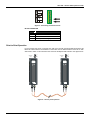
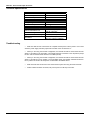
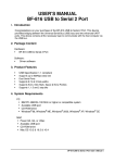
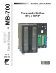
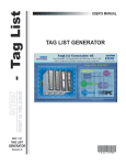
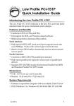
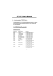
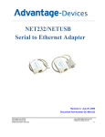
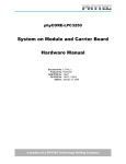
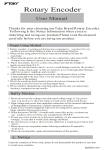
USER’S MANUAL OPT-700 - SERIAL TO FIBER OPTIC CONVERTER JUL / 05 OPT-700 VERSION 1 TM FOUNDATION OP T 7 0 0 ME smar www.smar.com Specifications and information are subject to change without notice. Up-to-date address information is available on our website. web: www.smar.com/contactus.asp OPT-700 – Serial to Fiber Optic Converter OPT-700 –Serial to Fiber Optic Converter (Supports Hot Swap) Part Number OPT-700 (EIA-232/EIA-485 to Fiber Optics Converter) Description The OPT-700 is a Fiber Optic Modem designed to provide a versatile connection between asynchronous serial communication interfaces such as EIA-232-C and EIA-485 using Fiber Optic cable. It will allow any piece of equipment that uses half-duplex asynchronous serial communication at distances up to 4.0 km with great benefit of EMI immunity. It can be configured point-to-point or in a multidrop configuration using the Repeat feature. The OPT-700 supports a broad range of configurable baud rates for the asynchronous serial communication. EIA-232-C can work between 2400 and 115.2Kbps, while EIA-485 works from 2400 till 920Kbps. Once Fiber Optic is immune to EMI/RFI and ground loops, the Modem can replace converters and isolators when connecting remote devices. Figure 1 - Serial to Fiber Optics Converter- OPT-700 Main Characteristics It works directly in the LC700/DFI backplane draining power from the Inter-Module-Bus (IMB). It can be used in a stand-alone mode with an external power supply. It accepts EIA-232-C or EIA-485 with configurable baud rates. It supports Point-to-Point or Multidrop Fiber Optic communication. It is a great solution to increase link distances and eliminate EMI or Grounding problems. Fiber Optic Cable This is a Dual or Simple multimode, 62.5 or 50/125µm fiber optic cable with ST connectors and a Maximum length of 4000m (12,000ft). 1 OPT-700 – Serial to Fiber Optic Converter Basic Installation Steps Set the internal jumper (J1) to use internal or external power supply. To remove the circuit board from the plastic module push with moderate pressure each tab (top and bottom) close to the grids, while forcing to separate the box from the front plastic panel. Decide which RS asynchronous interface is going to be used. Configure Switch #1 (see table below.) Find out the working baud rate and configure Switch #2 (high or low baud rate range) then turn on only one of the switches between #4 and #8. Determine the necessity to work with point-to-point or multi-drop connection and define all necessary cable, and then make sure the repeat Switch#2 is correctly configured on each OPT-700 converter. Make all connections and start the system. Follow the signal by the Rx and Tx LEDs on the front panel. They will blink according to the data across the fiber line. A.2 If there are any problems go to the “Troubleshooting” section of this Manual. OPT-700 – Serial to Fiber Optic Converter Installing the Module in the Rack Follow the steps below to install the module in the rack. Attach the top of the module (with a 45o inclination) to the module support located on the upper part of the rack. Mounting detail. Push the module fixing it to the module connector. Next, fix the module to the rack using a screwdriver, and fasten the fixation screw at the bottom of the module. 3 OPT-700 – Serial to Fiber Optic Converter Front Panel Overview The figure below shows the OPT-700 module with the front cover opened. From top to bottom we can see the DB9 connector for the EIA-232-C, the 5-position terminal for the EIA-485 and external power supply, 8 DIP switches for configuration, and finally the fiber optic receiver and transmitter. Note If the connection with the DB9 port is permanent, the DB9-EXT cable must be used to allow the panel to be opened. 12345678 Figure 2- Overview of the front panel Connecting in an External Source Using this modem as a stand-alone device requires that the internal jumper (J1) be removed from the default position and placed into the “external PS” position. The circuit must be removed from the box to modify the jumper configuration. Next connect an external power supply to terminal VDC +/-. The OPT-700 can work with a range of 12 to 30 Vdc and will drain a maximum current of 200mA. A.4 OPT-700 – Serial to Fiber Optic Converter Figure 3 - Connecting an external source RS-232 CONNECTOR Pin 1 2 3 7 Function Shield Receives Transmits Ground (Reference Signal) Point to Point Operation It is the simplest type of link. Configure each side of the link with the appropriate RS interface and Baud rate. Notice that the RS interfaces on both sides can be different and the baud rate on both sides need to match. In this case both units must have the Repeat Switch #2 OFF. See figure below. Switch#2 OFF To R S To R S Switch#2 OFF Figure 4 – Point to point operation 5 OPT-700 – Serial to Fiber Optic Converter Multi-drop Operation The OPT-700 can also be used for multiple drops by forming a ring configuration. In this way when a Master modem transmits the signal all of the slave devices are able to receive the information. The Master OPT-700 will be in the “Do Not Repeat” mode Switch#2 OFF while all slaves require Switch #2 set to the ON position (Repeat Mode.) Slave n Switch#2 ON To R S Slave 1 Switch#2 ON To R S To R S Master Switch#2 OFF Figure 5 - Multi- Drop Operation LC700 Applications The OPT-700 is a great solution for reliable long distance communications with the Smar LC700 Universal Hybrid Controller. • • • A.6 It can be used in the following ways: MODBUS Point-to-point to a computer for Monitoring or Configuration. Computer is the Master and LC700 is the Slave. MODBUS Multidrop. One computer connects to many LC700s and other MODBUS devices. Computer is the Master and all others are Slaves. Connect the LC700 CPU to the Remote I/O Interfaces. One RIO interface in point-to-point or more than one RIO in a multidrop repeat optical loop. OPT-700 – Serial to Fiber Optic Converter Configuring the DIP Switches 1 EIA - 232=off / 485=on = Switch 1 ON EIA-485=off / 232=on = Switch 1 OFF 2 Repeater ON= Switch 2 ON Repeater OFF = Switch 2 OFF ON 3 Higher baud rate Range = Switch 3 ON Lower baud rate Range= Switch 3 OFF 12345678 Ci rcui t Boa rd Switch settings for baud rate selection: Only one switch should be On to select the baud rate. Check switch # 3 for baud rate Range. Switch Lower baud rate Range Higher baud rate Range 4 4.8k 57.6k 5 9.6k 115.2k 6 19.2k 230.4k 7 38.4k 460.8k 8 76.8k 921.6k Figure 6 – Configuring the DIP Switches 7 OPT-700 – Serial to Fiber Optic Converter Technical Specifications IMB Power Consumption Current Consumption Internal Source 5 Vdc 1.9 W 260 mA max. Voltage Range Current Consumption External Source 10 to 35Vdc 80 mA @ 24 Vdc Optical Transmission 62,5 or 50/125 µm optical cable Optical Transmission Line with ST connectors Optical Wavelength 820 nm Typical Maximum Fiber Length 4000 m (12000 ft.) EIA-232, 2.4Kbps to 57Kbps Baud Rates EIA-485, 4.8Kbps to 920Kbps Troubleshooting • Make sure that all of the connections are complete and the power is ON. If power is not on then check the power supply selection jumper that is located on the circuit board “J1”. • While you are using the EIA-232 configuration, the EIA-485 should be disconnected and the switch # 1 should be in the off position. The repeater switch # 2 should be in the off position (except for OPT-700 connected to Slave devices in a multidrop mode). • While you are using the EIA-485 configuration, the EIA-232 should be disconnected and the switch # 1 should be in the on position. For the multidrop mode, the repeater switch#2 should be in the on position for all OPT-700 except the one attached to the Master device. A.8 • Make sure that all of the devices in the communication system are using the same baud rate. • All fiber cables should be connected, see point-to-point or multi-drop connection. Appendix A SRF – SERVICE REQUEST FORM Proposal Nº: OPT700 – Serial to Fiber Optic Converter COMPANY INFORMATION Company: _____________________________________________________________________________________________________ Unit: ________________________________________________________________________________________________________ Invoice: _______________________________________________________________________________________________________ COMMERCIAL CONTACT Full Name: ____________________________________________________________________________________________________ Phone: _________ _________________________ _________ _________________________ Fax: _______________________ E-mail: _______________________________________________________________________________________________________ TECHNICAL CONTACT Full Name: ________________________________________________________________________________________________ Phone: _________ _________________________ _________ _________________________ Extension: ____________________ E-mail: _______________________________________________________________________________________________________ EQUIPMENT DATA Model: ______________________________________________________________________________________________________ Serial Number: ________________________________________________________________________________________________ PROCESS DATA Process Type (Ex. boiler control): __________________________________________________________________________ Operation Time: ____________________________________________________________________________________________ Failure Date: __________________________________________________________________________________________________ FAILURE DESCRIPTON (Please, describe the failure. Can the error be reproduced? Is it repetitive?) ______________________________________________________________________________________________________________ ______________________________________________________________________________________________________________ ______________________________________________________________________________________________________________ ______________________________________________________________________________________________________________ OBSERVATIONS ______________________________________________________________________________________________________________ ______________________________________________________________________________________________________________ ______________________________________________________________________________________________________________ ______________________________________________________________________________________________________________ USER INFORMATION Company: _____________________________________________________________________________________________________ Contact: _______________________________________________________________________________________________________ Section: _______________________________________________________________________________________________________ Title: ________________________________________________ Phone: _________ _________________________ Signature:_______________________________________________ _________ _________________________ E-mail: ________________________________________________________________________ Extension: ___________________ Date: ______/ ______/ _________ For warranty or non-warranty repair, please contact your representative. Further information about address and contacts can be found on www.smar.com/contactus.asp A.1 OPT-700 – Serial to Fiber Optic Converter A.2