1
Section 16
CREATING A FIELDBUS STRATEGY BY
USING DF51
Introduction
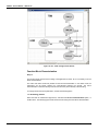
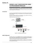
This section describes the strategy configuration by using the DF51 controller as Bridge. The control
loop is shown below.
PROJ_DF51
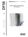
Figure 16. 1 – Example of temperature control process
The purpose of this process is to control the fluid output temperature (controlled variable) using
steam flow rate (manipulated variable) to heat it. The fluid temperature will be sent to the master
controller, where it will be compared to a temperature set point.
The master output would be the slave controller set point, which will control the steam flow rate to
the heat exchanger.
16.1
DFI302 – User’s Manual – AUG/14 - D
Starting the Area
Step 1
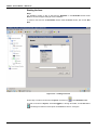
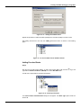
It is possible to create, or edit, an area from the Studio302. In the Studio302 interface select
Areas. A window will appear listing all areas of database.
To create a new area from the Studio302, left-click inside the Areas window, then choose New
Area.
Figure 16. 2 – Creating a new area
Another way to create a new area is from Syscon. Click the icon
in the Studio302 toolbar.
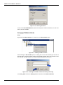
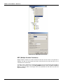
To create a new area on Syscon, choose File New, or through the toolbar, choose New button
. The dialog box shows the areas options. Select Area as shown in next figure:
16.2
Creating a Fieldbus Strategy by using DF51
Figure 16. 3 – Options to create Syscon areas
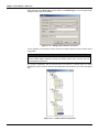
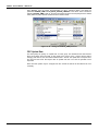
After choosing the area type, it opens a window to the user give a name to the new area.
Figure 16. 4 – New area name
Type the name for the area in the Area Name box, and click Ok. For this example, it chooses
Proj_DF51 name.
A new window will appear. This window has:
Application – Logical Plant. To insert control strategies into this part.
Fieldbus Networks – Physical Plant. To add devices and function blocks to the area into this
part.
Figure 16. 5 – Area divisions
Physical Plant Project
Step 2
, to select the Server.
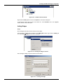
In the main window, PROJ_DF51, right-click the Fieldbus Networks icon,
Choose
Communication
Settings
option,
or
through
the
toolbar,
choose
CommunicationSettings. The communication settings dialog box will open:
16.3
DFI302 – User’s Manual – AUG/14 - D
Figure 16. 6 – Choosing the Server
Confirm if the Smar.DFIOLEServer.0 option has already been selected. Otherwise, the user must
select it, and then click OK.
Arranging Fieldbus windows
Step 3
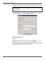
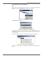
Right-click the Fieldbus Networks icon, and then choose New Fieldbus option.
Figure 16. 7 – Adding a Fieldbus channel
When selecting the New Fieldbus option, the dialog box to choose the channel type and name it
with tags opens. If the user needs to name the channel with a specific tag, it must be written in this
box. After that, click OK. Otherwise, the default tag will be attributed to the channel.
Figure 16. 8 – Selecting the Fieldbus channel and naming it with a tag
In the PROJ_DF51 window, the CANAL_00 will be inserted into the Fieldbus Networks:
16.4
Creating a Fieldbus Strategy by using DF51
Figure 16. 9 – Fieldbus channel inserted
Right-click the CANAL_00 icon and choose Expand. A new window will appear.
To arrange the screen, click the main area window. So, choose Window menu on the Syscon
toolbar, and then choose Tile option.
Adding Bridges
Step 4
Now the bridges that will be used for this area can be added.
First, the DF51 controller must be inserted. In the PROJ_DF51 window, right-click the CANAL_00
icon. Select New Bridge as shown in the next figure:
Figure 16. 10 – Inserting the bridge to the area
After inserting the Bridge, it opens a window as shown below.
Figure 16. 11 – Setting the Bridge
16.5
DFI302 – User’s Manual – AUG/14 - D
Select DF51 in the Device Type box. In the Device Tag box, type DFI or another tag, and click OK.
IMPORTANT
Not all characters are valid when naming the elements, so pay attention:
The valid characters are:
A-Z a-z 0-9 # { } [ ] ( )+ The invalid characters are:
~ ` ! @ # $ % ^ & * = | : ; , . < > ? / ' " \
, Select Attributes option to see the bridge’s
In the CANAL_00 window, right-click the DFI icon,
attributes and, if necessary, change its tag. Click OK. See the next figure:
Figure 16. 12 – Bridge attributes
Adding Fieldbus Devices
Step 5
After adding the bridge for the area, it is possible to insert the field devices. First, return to the
PROJ_DF51 window and right-click the CANAL_00 channel. Select NewDevice
The dialog box for choosing the device and naming it with a tag will be shown. The user can select
Smar in the Manufacturer box, select TT302 in the Device Type box, and then name this device
with the tag TIC001, or with another tag. After finishing, click OK:
16.6
Creating a Fieldbus Strategy by using DF51
Figure 16. 13 – Setting the Fieldbus Device
Repeat this procedure to add a transmitter (LD302) and a converter (FI302) in the flow control.
After adding the devices to the area, the CANAL_00 channel will be as shown in the following
figure:
Figure 16. 14 – Device added into the Fieldbus channel
Adding Function Blocks
Step 6
Now the user can add Function Blocks. To add a new Function Block (FB), click the
right-click the Virtual Field Device (FB VFD) icon. Select New Block item.
sign, and
The FB VFD is responsible for the data management.
Figure 16. 15 – Selecting new blocks
The Function Block Characterization dialog box will appear. The Block Type option shows the
Smar’s FB.
16.7
DFI302 – User’s Manual – AUG/14 - D
Select the block in the Block Type box and name it in the Block Tag box. The next figure shows
adding the Analog Input function block.
Figure 16. 16 – Adding function blocks to the device
For this example, it is necessary to add AI, PID and AO function blocks to build a cascade control
configuration.
NOTE
From the Syscon version 6.00, it is not necessary to configure the Transducer (TRD),
Resource Block (RES), Diagnostics (DIAG) and Display (DSP) blocks, because they are
preinstantiated in the devices.
The channel configuration with all function blocks and devices is showed below. For better
identification of the Transducer, Resource and Diagnostics function blocks name them with specific
tags.
Figure 16. 17 – Fieldbus channel composition
16.8
Creating a Fieldbus Strategy by using DF51
Now the strategy on the Application (Logical Plant) can be developed. First it is necessary to
establish a new process cell.
Creating New Process Cells
Step 7
The Logical Plant can be divided in several process cells, according to the plant.
To create a new process cell, right-click the Application icon and select New Process Cell item.
Figure 16. 18 – Adding a Process Cell
The dialog box to attribute the tag to the Process Cell will open:
Figure 16. 19 – Attributing tag to the Process Cell
If the user needs name the Process Cell with a specific tag, can enter it in the Tag box, and click
OK. To create more process cells, the procedure above has to be repeated.
After inserting the Process Cell, the PROJ_DF51 window will be according to the following figure:
Figure 16. 20 – Area window after inserting the Process Cell
NOTE
The user must remember that Application is a virtual division. It only divides a large plant.
For example: if the plant has two networks, they can be FB (FBApplications) in the Syscon.
One Application can have several FB Applications, but a FB Application can not be in
more than one Application.
16.9
DFI302 – User’s Manual – AUG/14 - D
Creating a Control Module (FBApplication)
Step 8
Now the user can create a Function Block Application, Control Module, in the Application section.
Right-click the FBAP_01 icon and select Expand item.
Figure 16. 21 – Creating a FB Application
To arrange the screen, click the area window. So, choose the Window menu on the Syscon toolbar
and then choose Tile option.
Return to the FBAP_01 window. Right-click the FBAP_01 item and choose New Control Module.
See the next figure.
Figure 16. 22 – Creating the new Control Module
The Control Module dialog box will appear. Name it with a tag related to the Process Cell. Click OK
to conclude this task.
Figure 16. 23 – Attributing tag to the Control Module
IMPORTANT
Remember that not all characters are valid when naming the elements with tags.
The valid characters are:
A-Z a-z 0-9 # { } [ ] ( )+ The invalid characters are:
~`!@#$%^&*=|:;,.<>?/'"\
16.10
Creating a Fieldbus Strategy by using DF51
Inserting Blocks in the Control Module
Step 9
Now the user can add function blocks for the devices in the Logical Plant. Right-click the
FBAP_01_1 item and select Attach Block option, as shown in the next figure.
Figure 16. 24 – Attaching blocks to the FBAP
The Attach Block dialog box will open:
Figure 16. 25 – Inserting blocks to the FB Application
The available function blocks for the Control Module are showed in the Attach Block box. For the
aimed strategy, the function blocks that must be inserted will appear in the box. So, select them one
by one, and click OK.
When the Attach Block process ends, the Control Module will be as shown in the next figure:
Figure 16. 26 – Blocks added to the FB Application
Another way to attach the blocks to the Control Module is left-clicking the element and drop it to the
window.
16.11
DFI302 – User’s Manual – AUG/14 - D
Configuring the Control Strategy
Step 10
Now the user is ready to develop the control strategy.
First, right-click the FBAP icon and choose Strategy. The Strategy window will appear as shown in
the following figure.
Figure 16. 27 – Strategy window
At this moment there are 3 or 4 windows opened in the Syscon. Minimize the CANAL_00 window.
To arrange these windows, click the FBApplication window, and then the Proj_DF51 window. On
the toolbar, choose Window Tile.
If the user does not have a monitor upper than 17", it is recommended to minimize the strategy
window. Thus the whole area can be visualized.
The strategy window offers several tools for drawing. Refer to the Syscon’s Help for further details.
Adding Blocks to the Strategy window
Step 11
Now the function blocks can be added to the FBAP_01_1 window.
In order, click the first block,
will be created automatically.
, and drop it into the strategy window. A function block
The following figure shows the function block added to the strategy window:
Figure 16. 28 – Block inserted into the strategy window
16.12
Creating a Fieldbus Strategy by using DF51
The drag-and-drop procedure must be repeated for the other blocks such as TIC001_PID,
FT101_AI, FT101_PID e FCV101_AO.
Linking the Blocks
Step 12
There is a specific tool to link the blocks, the Link button,
, on the Strategy toolbar.
Click this button on the toolbar, and then in the TIC001_AI function block. The dialog box for linking
the input and output parameters will appear. Select OUT, and then click the OK button as shown in
the following figure.
Figure 16. 29 – Linking the function blocks
Move the mouse cursor up to the block that will be linked.
The user also does the fast link procedure just right-clicking the function block.
The links necessary for this strategy are:
Direct Links:
•
OUT(TIC001_AI) IN(TIC001_PID)
•
OUT(TIC001_PID) INFT101_PID)
•
OUT(FT101_PID) CAS_IN(FCV101_AO)
•
OUT(FT101_AI) CAS_IN(FT101_PID)
Back Links:
•
BKCAL_OUT(PID_LD302) CAS_IN(PID_TT302)
•
BKCAL_OUT(AO_FI302) BKCAL_IN(PID_LD302)
After linking the parameters specified above, the strategy window will be as shown in the following
figure.
16.13
DFI302 – User’s Manual – AUG/14 - D
Figure 16. 30 – Links among function blocks
Function Block Characterization
Step 13
The function blocks must be set according to the application for them. So, it is necessary to do the
block characterization.
The online and offline modes are possible for the block characterization. In the offline mode, the
parameters are set before starting the communication between the devices. The online
characterization is executed directly in the devices when the plant is already communicating.
To change the function block parameters, consider the following topics:
1. In the Strategy window
Select the block to characterize. Right-click it, and select the Off Line Characterization option, or
double-click it. The following figure shows the block that is being done the offline characterization:
16.14
Creating a Fieldbus Strategy by using DF51
Figure 16. 31 – Offline characterization in the Strategy window
2. In the CANAL_00 window
Another way to do the offline characterization is right-clicking the function block, and then selecting
the Off Line Characterization option, as shown in the next figure:
Figure 16. 32 – Offline characterization in the Fieldbus channel window
16.15
DFI302 – User’s Manual – AUG/14 - D
For both situations, the Off Line Characterization dialog box will appear:
Figure 16. 33 – Function Block Characterization dialog box
Double-click at the right side of the parameter to change it. Another option is click once, and then in
the Edit button to start editing the parameter value. At the ending, click the End Edit button.
Figure 16. 34 – Editing the parameter in the Function block Characterization box
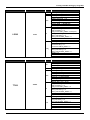
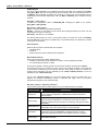
The list below shows the parameters that must be set for this area:
16.16
Creating a Fieldbus Strategy by using DF51
DEVICE
TAG
BLOCK
TR
RS
DSP
LD302
FT101
AI
PID_1
DEVICE
TAG
BLOCK
TR
RS
DSP
TT302
TIC001
AI
PID
PARAMETER
MODE_BLK.Target = AUTO
MODE_BLK.Target = AUTO
MODE_BLK.Target = AUTO
BLOCK_TAG_PARAM_1= FT101_AI
INDEX_RELATIVE_1 = 8
MNEMONIC_1 = VAZAO
ACCESS_1 = MONITORING
ALPHA_NUM_1 = MNEMONIC
DISPLAY_REFRESH = UPDATE DISPLAY
MODE_BLK.Target = AUTO
XD_SCALE.EU_100 = 100
XD_SCALE.EU_0 = 0
XD_SCALE.UNITS_INDEX = inH2O(4ºC)
OUT_SCALE.EU_100 = 100
OUT_SCALE.EU_0 = 0
OUT_SCALE.UNITS_INDEX = %
CHANNEL = 1
L_TYPE = INDIRECT
MODE_BLK.Target = AUTO
PV-SCALE.EU_100 = 100
PV-SCALE.EU_0 = 0
PV-SCALE.UNITS_INDEX = %
OUT_SCALE.EU_100 = 100
OUT_SCALE.EU_0 = 0
OUT_SCALE.UNITS_INDEX = %
GAIN = 0.5
RESET = 1
RATE = 0
PARAMETER
MODE_BLK.Target = AUTO
SENSOR_TYPE = PT100IEC
SENSOR_CONNECTION = THREE WIRES
SENSOR_TRANSDUCER_NUMBER = 1
MODE_BLK.Target = AUTO
MODE_BLK.Target = AUTO
BLOCK_TAG_PARAM_1 = TT100_AI
INDEX_RELATIVE_1 = 8
MNEMONIC_1 = TEMP
ACCESS_1 = MONITORING
ALPHA_NUM_1 = MNEMONIC
DISPLAY_REFRESH = UPDATE DISPLAY
MODE_BLK.Target = AUTO
XD_SCALE.EU_100 = 500
XD_SCALE.EU_0 = 0
XD_SCALE.UNITS_INDEX = ºC
OUT_SCALE.EU_100 = 100
OUT_SCALE.EU_0 = 0
OUT_SCALE.UNITS_INDEX = %
CHANNEL = 1
L_TYPE = INDIRECT
MODE_BLK.Target = AUTO
PV_SCALE.EU_100 = 100
PV_SCALE.EU_0 = 0
PV_SCALE.UNITS_INDEX = %
SP = 50
GAIN = 0.5
RESET = 1
RATE = 0
16.17
DFI302 – User’s Manual – AUG/14 - D
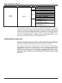
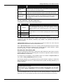
DEVICE
TAG
BLOCK
TR
RS
DSP
FI302
FCV101
AO
PARAMETER
MODE_BLK.Target = AUTO
TERMINAL_NUMBER = 1
MODE_BLK.Target = AUTO
MODE_BLK.Target = AUTO
BLOCK_TAG_PARAM_1 = FCV102_AO
INDEX_RELATIVE_1 = 9
MNEMONIC_1 = VALVULA
ACCESS_1 = MONITORING
ALPHA_NUM_1 = MNEMONIC
DISPLAY_REFRESH = UPDATE DISPLAY
MODE_BLK.Target = AUTO
PV_SCALE.EU_100 = 100
PV_SCALE.EU_0 = 0
PV_SCALE.UNITS_INDEX = %
XD_SCALE.EU_100 = 20
XD_SCALE.EU_0 = 4
XD_SCALE.UNITS_INDEX = mA
After the parameter setting, the user can start the equipment communication. It is necessary
commissioning the devices in order to attribute the tags, IDs and device addresses properly. If this
procedure is not executed, the Syscon will detect the noncommissioned device and the download
for this device will be aborted. Finishing the equipment commissioning, the download process can
start. The download process can be executed, for example, returning to the Proj_DF51 window,
right-clicking the Fieldbus Networks icon,
, and selecting the Download option. For further
details about the available download types, refer to the Syscon manual.
Optimizing the Supervision
There are some important steps to be done in the DF51 configuration that can improve the
supervision time. Before starting these procedures, a brief description of the System302 architecture
is presented to facilitate the understanding of the effects of changes in each parameter.
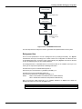
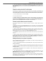
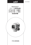
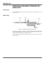
Take a look in the next figure. The user will be able to follow the data flow from source (field device)
to the destination (HMI). Starting in the field device, the data is collected by DFI302 during the
Background time included in the Fieldbus macrocycle. When using MVC (Multiple Variable
Container), these data are grouped in an optimized way. The Supervision Time controls the rate
that a MVC is read from the field device. Each Update Time, DFI302 sends the data to DFI OLE
Server which updates its database. All the OPC Groups will be updated according to the OPC
Update Rate.
16.18
Creating a Fieldbus Strategy by using DF51
OPC Client (HMI)
OPC Update Rate
DFI OLE Server
(OPC Server)
Update Time
DFI302
Background Time,
Supervision Time &
MVC
Field
Device
Figure 16. 35 – SYSTEM302 Architecture
The next steps must be configured in order to get a better and optimized time for each system.
Background time
One of the first parameters to be set is Background time (or Background traffic). The Syscon
calculates the macrocycle according to the number of links in the configuration and allows the user
to add a Background time. A minimum value is automatically set by Syscon, and must be calculate
to have an ideal background to each Fieldbus Network.
The Background time is calculated based on the formula used for the Fieldbus macrocycle. The
macrocycle is composed of Operational and Background traffics.
The ideal macrocycle for non-Redundant Systems is:
Ideal macrocycle non-Redundant = ((30*NDEV)+(30*NEL))*1.2
The ideal macrocycle for Redundant Systems is:
Ideal macrocycle Reduntant = ((60*NDEV)+(30*NEL))*1.2
Where,
NDEV is the Number of Field Devices in the Fieldbus Network
NEL is the Number of External Links (between Field Devices)
After you know the ideal macrocycle, go to Fieldbus Attributes on Syscon and adjust the
Background Traffic to the new and acceptable value.
IMPORTANT
Once adjusted in every Fieldbus Channel, run a complete configuration download.
16.19
DFI302 – User’s Manual – AUG/14 - D
Figure 16. 36 – Adjusting the macrocycle
MVC (Multiple Variable Containers)
Multiple variable containers are a data container that will have all device data. If this parameter is
disabled, the data are sent through block views. Each block has four views that give a lot of
overhead to the communication.
The MVCs come to optimize this communication sending only one big packet per device instead of
four small ones per block. Just set the MVC_ENABLE parameter inside the DF51 Transducer
Block to enable this feature. All changes done on this parameter will take effect only after new
Supervision startup.
16.20
Creating a Fieldbus Strategy by using DF51
Figure 16. 37 – Setting the MVC_ENABLE parameter
Supervision Time
The Supervision Time is the time required for the DF51 to collect all field device's data and submit to
the supervision workstation. Remember that these data are sent through the Background time of the
macrocycle.
During the Supervision time, the internal database is refreshed. Therefore, this procedure only
makes sense in a system that is already up and running, together with all HMI (Human Machine
Interface) software.
The DF51 transducer block has three other parameters that are also used to optimize the
supervision in System302.
• Parameter 1: SUP_UPDATE_CONFIGURED_ms
• Parameter 2: SUP_UPDATE_SUGGESTED_ms
These two parameters define the time that the bridge has to poll the supervision data from the
devices. Start setting up the SUP_UPDATE_CONFIGURED_ms as 2 times the ideal macrocycle.
After 10 minutes approximately, the parameter SUP_UPDATE_SUGGESTED_ms will indicate an
optimal time and a change may be done again.
• Parameter 3: NO_DATA_CHANGE_TIMEOUT_ms
On data change is a mechanism to optimize the data transference between the bridge and the HMI
software. With this mechanism the bridge will only send data that has changed.
The HMI has a timeout for the data, i.e., if it does not receive a communication point after a certain
period
it
will
indicate
lack
of
communication.
Here
is
the
point
where
NO_DATA_CHANGE_TIMEOUT_ms comes in. This parameter defines the timeout to the bridge. If
a certain value does not change over that period, it will be sent to the HMI anyway, avoiding the
expiration of the HMI timeout.
NOTES
- Good values for the NO_DATA_CHANGE_TIMEOUT_ms parameter are between 2500 and
6000, depending on the loaded configuration.
- All the changes done on this parameter takes effect after new Supervision startup.
Update Time
The UPDATE_TIME is used by DF51 to refresh the DFI OLE Server database.
Normally only the dynamic data
NO_DATA_CHANGE_TIMEOUT.
are
refreshed.
Static
data
are
refreshed
each
16.21
DFI302 – User’s Manual – AUG/14 - D
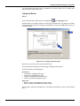
Using Syscon, open the Online Characterization for DF51 Transducer Block, and adjust the
parameters UPDATE_TIME and NO_DATA_CHANGE_TIMEOUT to the values. Have in mind that
adjusting UPDATE_TIME to 200 ms, the DF51 will refresh the data more frequently than the default
value (1000 ms) and it will load a little bit more the Ethernet traffic.
Figure 16. 38 – Setting the UPDATE_TIME parameter
OPC Update Rate
The client (HMI) can specify an “update rate” for each group. This determines the time between
when the exception limit is checked. In other words, if the group is set to 1 second, but the data is
changing each 500 ms, the client will be advised each 1 second. The update rate is a request from
the client and the server will respond with an update rate that is as close as possible to that
requested.
Each client has specific ways to configure this rate. Consult the manual for the HMI and do it as
necessary.
16.22
Section 17
ADDING REDUNDANCY TO THE DF51
CONTROLLER
Introduction
The main key for fault tolerance and in order to achieve the great system availability is to have
redundant devices. DF51 controllers are able to work in a Hot Standby* redundancy mode, which
offers redundancy for all its functionalities and databases.
Also there is an option to work with the legacy mode LAS (Link Active Scheduler) redundancy. This
chapter will present the characteristics of each mode and the procedures that the user should follow
to configure the system in a redundant way. Here follows an overview of the modes.
Hot Standby Redundancy
With the Hot Standby mode full redundancy is achieved, heavily improving the plant availability and
safety. This mode offers redundancy for all the DF51 functionalities and databases:
-
Gateway: 1 Ethernet port ↔ 4 H1 ports;
-
Link Active Scheduler (LAS);
-
Controller (running Function blocks);
-
Modbus Gateway.
NOTE
TM
A Link Active Scheduler (LAS), equipment is the entity in the FOUNDATION fieldbus H1 network
responsible for coordinating the communication, i.e. it basically dictates when each device is
allowed to publish/subscribe data to/from the FOUNDATION fieldbus H1 network.
That is, the same redundancy capability achieved with the legacy mode “LAS redundancy”, with the
Hot Standby mode is achieved too.
This mode suits specially the cases where the DFI302 has function blocks in its configuration.
Function blocks on DFI302 can be interesting mainly in two cases:
-
Integration to legacy systems through Modbus protocol (using Modbus function blocks);
-
Advanced function blocks or strategies (DFI302 execute function blocks with much better
performance than the field devices).
The procedures for configuration and maintenance are as simple as for a non-redundant system,
saving time to get the system running. Only one configuration download is necessary to configure
the redundant pair at the first plant start-up. And in the case of replacement of a failed module none
download of configuration or user intervention is necessary. The new module inserted is
automatically commissioned, receiving the whole configuration from the module in operation.
Since the system supports the modules placed physically separated (even far from each other),
common fault causes are avoided. In other words, with the processor modules placed at different
backplanes, or even at different rooms, failures in one of the backplanes or in one of the rooms will
not affect the whole system.
* Hot Standby: “Redundancy strategy where the Standby module is powered and synchronized with the Active module, standing
ready to assume if necessary”.
17.1
DFI302 – User’s Manual – AUG/14 - D
NOTES
TH
- The 4 FOUNDATION fieldbus H1 channel is used as the synchronization path between the
modules. Thus, this channel will not be used as a usual FOUNDATION fieldbus H1 channel and
should not have devices connected.
- DF51 in Hot Standby mode uses the flat address “0x05” when it publishes. Because third-party
devices do not support the flat address, they are not able to establish links with the DF51 in Hot
Standby redundancy.
- Hot Standby redundancy is available only for SYSTEM302 Version 6.1.7 and above.
Link Active Scheduler (LAS) Redundancy
This is a legacy mode of redundancy suitable only for the case where DF51 does not have function
blocks in its configuration. That is, in such case the function blocks are on the field devices. This is a
completely distributed control philosophy where DF51 perform two main functions:
•
Gateway: 1 Ethernet port ↔ 4 H1 ports;
•
Link Active Scheduler.
For this scenario, with the LAS redundancy the control, operation, and supervision redundancies are
also guaranteed.
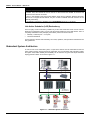
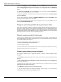
Redundant System Architecture
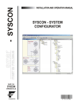
In order to have a true redundant system, not just all the devices must be redundant but also the
entire system topology must be thought as redundant. The more elements with redundancy ability
the system have, better reliability and availability can be achieved. A typical and simple redundant
topology based on DF51 can be seen in figure 17.1.
Workstation Redundancy
Network Redundancy
Sm a
r F irst i nFiel dbus
Hot Standby or
LAS Redundancy
Figure 17.1 – Redundant System Architecture
17.2
Adding Redundancy to the DF51 Controller
System Pre-requirements
The requirements listed here apply to both redundancy modes.
The version of firmware for redundant systems has the termination "R". It indicates a firmware
suitable for redundant applications. With the redundant firmware, the module initializes by default in
Hot Standby mode, in a safety state called “Sync_Idle”. The user as will be seen forth can change
the redundancy mode later, if necessary.
The Syscon configuration should be created as it is usually done for a non-redundant system (in
case of questions, please refer to section 3 of this manual). The unique difference (now that
redundancy is involved) is that it is necessary to add a transducer function block to the bridge. This
transducer will be used then to initialize the redundancy.
In the Syscon configuration, the tag for the transducer block can be any, preferentially a meaningful
tag concerned to the DF51 tag or to the plant. Be careful to not use tags already in use in the same
plant. Further information on Syscon operation, can be found in its own manual.
For any of the redundancy modes it is necessary first of all to configure the network redundancy.
Refer to the Configuring Servers section for further details.
Configuring Hot Standby Redundancy
In order to enable the Hot Standby redundancy and monitor its status, some parameters available in
the DF51 transducer block should be used.
Most redundancy parameters have a suffix. The suffix “L” means Local, or that the parameter brings
information of the module that is being monitored directly through the DFI OLE Server. The suffix
“R” means Remote, or that the parameter brings information that the Local module knows about the
other module through the synchronization path.
Here is presented a functional description of these parameters in order to understand how the Hot
Standby redundancy works. For further information on these parameters see also the transducer
block description table (Function Blocks manual).
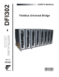
TAG_DESCRIPTION
This parameter shows the DF51 serial number to allow the identification of controller with problem.
Figure 17.2 – TAG_DESCRIPTION parameter shows the DF51 Serial Number
17.3
DFI302 – User’s Manual – AUG/14 - D
FUNCTION_IDS
This is the unique parameter to be configured. The user must assign one module to be the Main
setting Sync_Main. After that, through the synchronism path the other one automatically will be set
as Backup. This designates physically who should be, in other words, the Preferential and the
Redundant processor module respectively. This way, Main and Backup can be understood simply
as labels.
RED_ROLE_L / RED_ROLE_R
It reflects the configuration made at FUNCTION_IDS, identifying the Role of the module,
Sync_Main or Sync_Backup.
RED_STATE_L / RED_STATE_R
Active - runs all the tasks and generates all the data.
Standby – does not run the tasks, but just receives all the data generated by the other one and
stands ready to assume, if necessary.
Not Ready – redundancy is not available.
The different failures that may occur in such system, lead it to a switch over, when the Standby
becomes Active and vice-versa in a bumpless way. The possible reasons for a switch over, divided
in two types, are as follows:
General Failures
When the whole processor module fails, this comprises:
• Hardware failure
• Power off
• Removal of the processor module from the backplane.
Bad Condition Failures
When one of the processor module interfaces fails:
• Modbus communication failure (hardware or cable; in case of operating as master).
• H1 channel failure (hardware or cable).
The system is capable of checking which one has the best conditions, electing it as the Active.
It is certain the recovery of one failure at a time. That is, once a fail has occurred, a second fail will
be recovered by redundancy just if the first fail has been fixed. While the failure is not fixed, the
system has the redundancy not fully available (in case of Bad Condition Failures) or even not
available (in case of General Failures).
For the case of General Failures, as soon as the failed module recovers a healthy state or is
replaced, the modules automatically become a redundant pair again. That is, the system
automatically recognizes a new inserted module.
RED_SYNC_STATUS_L / RED_SYNC_STATUS_R
This parameter reflects all the possible status of the synchronism between the modules.
SYNC STATUS
17.4
DESCRIPTION
Stand Alone
Just one module is operating. If the system has been synchronized at least
once, and this value appears, it indicates that the other module had a
General Failure.
Synchronizing
The modules are checking their configuration with each other in order to
reach the Synchronized status. It can take up to 9 minutes at maximum
(while the system waits for the module in “Not Ready” state get its live lists
completed).
Updating Remote
Just after the download of the configuration, the module transfers the whole
configuration to the other one through the synchronism path.
Maintenance
The module is being configured by the other module through the
synchronism path or by the Syscon. If it appears for both “L” and “R”
parameters it indicates that none of the modules have been configured.
Synchronized
The modules are in perfect synchronism. The Active continuously updates
the Standby databases.
Adding Redundancy to the DF51 Controller
SYNC STATUS
DESCRIPTION
Warning: Role
Conflict
If a spare module is connected in the panel with the same Role of that one is
already running, this warning is shown. The procedure to fix this conflict is to
perform a Factory Init in the spare module.
Warning: Sync
Cable Fail
If a failure occurs in the synchronism cable, this warning is shown. The
system will not have the redundancy until the synchronism cable is fixed.
Warning: Updating
Remote Fail
If a failure occurs in the transfer of configuration from the Active to the
Standby, this warning is shown. The procedure is to perform a Factory Init in
the module that is not Active and wait until the transfer is completed
successfully.
RED_BAD_CONDITIONS_L / RED_BAD_CONDITIONS_R
It can present one or more value (concatenated) as follows:
BIT
BAD CONDITION
DESCRIPTION
0
Modbus
When working as master and if no Modbus slave device answers, it
means that Modbus communication is in bad conditions. It can be
caused by failures on the communication path or even a failure on the
slave.
1
H1-1
2
H1-2
3
H1-3
4
LiveList
Indicates failure on an H1 channel, specifying each channel had the
failure.
Indicates that the some Live List was not completed.
The desirable and most probable value is <none> for both modules (L and R), which assures good
conditions for both, and therefore, redundancy fully available. This parameter can have two
functions as follows:
A Bad Condition failure for the Active module leads the system to a switch over. In this case, this
parameter acts as record of the reason of the last switch over.
When a Bad Condition failure occurs for the standby module this parameter shows this condition
as an alarm. Thus, warning the operator that the standby presents a specific problem, it allows
proactive maintenance in order to have redundancy fully available.
RED_MAIN_WDG / RED_BACKUP_WDG
These are watchdogs that indicate the communication status between the HMI and the processor
modules. While their values are incrementing within 2 seconds the respective network connections
(Main and Backup) are working fine.
As a simple rule, the redundancy is fully available, ONLY if the modules are Synchronized and
have <none> in BAD_CONDITIONS parameters (L and R).
The following operations can be performed without process interruption: replacing a module with
failure, fixing the system when the H1 cable breaks, firmware update, and adding redundancy to a
system in operation.
NOTE
The most new DF51 modules have a LED labeled as “Standby” at the front to indicate the
redundancy state of the module.
When the LED is “on”, it means that the module is in standby. When the LED is “off”, the module
may be either in Active or Not Ready. If one of the modules is in Standby, the other is surely in
Active.
In the next paragraph there are some steps for the Hot Standby Redundancy configuration and
maintenance. It is recommended that the steps are all read and understood before are executed.
17.5
DFI302 – User’s Manual – AUG/14 - D
First time configuration procedure
This is the procedure to configure the system with Hot Standby Redundancy for the first time, at the
plant start-up.
1 - With the H1 connector disconnected, execute a Factory Init in both modules in order to grant the
default state.
2 - Connect both modules together, through the H1 channels (1 to 4).
3 - Open the desired configuration in the Syscon and put it in On-line mode. Right-click the bridge
icon and in the option Attributes choose one of the modules listed in the field Device Id. The
chosen module will be that one to be configured as Main. In the main window, right-click the icon
and then select Export Tags option on the popup menu.
4 - Even in the bridge icon, right-click the field FB VFD, and then choose Block List. A new window
will open showing all the blocks pre-instantiated in the module. In this window, right-click the
transducer
performing an Assign Tag with the tag that is predicted in the configuration. Close
the Block List window.
5 - Right-click the transducer icon in the bridge and choose On Line Characterization (see note
about operation modification of DF51 in the SYSTEM302 V7.x or higher). Set the parameter
FUNCTION_IDS as Sync_Main. Through the synchronism path, the other module automatically will
be initialized as Backup. After that, both the parameters RED_SYNC_STATUS (L and R) will
indicate Maintenance, which means that neither of the modules was configured yet.
6 - If necessary, perform Assign Tag for all the field devices. Wait until the Live Lists of all the
channels are complete. So, configure the system through the Active module executing all necessary
downloads exactly the same way for a non-redundant DFI302 system.
7 – As soon as downloads are completed successfully, the transducer will show the following
phases:
•
The Active will transfer the whole configuration to the other module (RED_SYNC_STATUS_L
as Updating Remote and RED_SYNC_STATUS_R as Maintenance).
•
After the configuration is successfully transferred, the modules can take some time to
synchronize (RED_SYNC_STATUS parameters (L and R) as Synchronizing). This is the time
necessary to the modules to check the configuration with each other.
•
Finally, the modules will synchronize (RED_SYNC_STATUS parameters (L and R) as
Synchronized and RED_STATE_R as Standby). Once the system is on these conditions, the
Active will be constantly updating the Standby.
NOTE
About operation modification of DF51 in the System302 V7.x or higher
Any change of name and number of blocks in DF51 will only be recognized by SYSTEM302 v7.x
after new startup of OPC Server. This is due to change in the default configuration of
TOPOLOGY_CACHE = ON parameter in the configuration file SmarOleServer.ini.
Firmware version V3.9.5 or higher eliminates the need to restart the OPC server.
Changing the configuration
Just follow the steps 6 and 7 of the section “First time configuration procedure”.
Replacing a module with failure
1 - With the H1 connector disconnected, insert the new module in the backplane.
2 - Update the firmware in the new module, if necessary. Perform a Factory Init in the new module in
order to grant the default state.
3 - Connect the H1 connector to the new module.
17.6
Adding Redundancy to the DF51 Controller
4 - The new module will be automatically recognized by the Active and both will stay in
Synchronizing for some time. As soon the system get the Synchronized status and <none> in the
BAD CONDITIONS parameters, the redundancy will be fully available and failure simulations can be
performed.
Fixing the system when the H1 cable breaks
If a fail occurs in a segment of H1 line such that it affects only one module, the redundancy will
cover this fail. But, if the H1 cable is reconnected at once, the noise introduced in the line will cause
communication problems for some time. In order to avoid that problem, follow the procedure below.
1 - Put the module affected by H1 cable fail in Hold.
2 - Fix up the cable connection.
3 - Perform a Reset in the affected module in order it returns operating. The module will be
automatically recognized by the Active and both will stay in Synchronizing for some time. As soon
the system get the Synchronized status and <none> in the parameters BAD CONDITIONS, the
redundancy will be fully available and failure simulations can be performed.
Firmware update without process interruption
This procedure describes how to update the firmware of both the modules without process
interruption.
1 – Be sure the system is in the Synchronized status and it has <none> in the parameters BAD
CONDITIONS. So, use FBTools to update the firmware of the Active module. At this moment, the
other module will take over.
2 - After the firmware update was finished, the modules will start to synchronize with each other,
with the Active transferring all the configuration to the other one. Wait for the system get the
Synchronized status and it has <none> in the BAD_CONDITIONS parameters.
3 - Use FBTools to update the firmware of the Active module. At this moment, the other module will
take over.
4 - After the firmware update was finished, the modules will start to synchronize with each other,
with the Active transferring all the configuration to the other one. As soon the system get the
Synchronized status and has <none> in the parameters BAD_CONDITIONS, the redundancy is
fully available again and failure simulations can be performed.
Adding redundancy to a system in operation
If a non redundant system is intended to be redundant in the future, at the plant start-up, the
following conditions must be obeyed:
th
1 - The 4 H1 port should be reserved as synchronization path. That is, this port should not have
devices connected to it.
2 - Predict H1 channels cabling considering that a Backup module will be added in the future (the
H1 channels of the Main module should be connected in parallel with the respective H1 channels of
the Backup module).
3 - Predict that the LAN architecture can be expanded, in order to attend what is described in the
Redundant System Architecture.
4 - The single module should use a redundant firmware (a version terminated in R). The
FUNCTION_IDS parameter should be set as Sync_Main. This way the module will work in Stand
Alone state and will be ready to recognize a new pair inserted at any time.
Obeying these conditions, redundancy can be added at a later time without process interruption.
The procedure to add redundancy to the system is just follow the same steps described in the
section “Replacing a module with failure”.
17.7
DFI302 – User’s Manual – AUG/14 - D
Configuring LAS Redundancy
In the next paragraph there are some steps for the configuration and maintenance of this legacy
mode. It is recommended that the steps are all read and understood before are executed.
First time configuration procedure
This is the procedure to configure the system with LAS Redundancy for the first time, at the plant
startup.
Active Module
1 - With the H1 connector disconnected, execute a Factory Init in both modules to grant the default
state.
2 – Connect the H1 connector to the Active module. Keep the Backup module with the H1 connector
disconnected for a while.
3 - Open the desired configuration in the Syscon and put it in On-line mode. Right-click the bridge
icon and with the option Attributes choose the module to be configured as Active in the field
Device Id.
4 - Even in the bridge icon, right-click the field FB VFD, and then click Block List. A new window
will be opened showing all the blocks preinstantiated in the module. Then, in this window, right-click
the transducer performing an Assign Tag with the tag that is predicted for the Active in the
configuration. Close the Block List window. In the main menu go to Export and click Tags.
5 - Right-click the transducer icon in the bridge and choose On Line Characterization (see note
about operation modification of DF51 in the SYSTEM302 V7.x or higher). Set the FUNCTION_IDS
parameter as Active.
6 - Even in the transducer, set the SYSTEM_OPERATION parameter as Redundant.
7 - If necessary, perform Assign Tag for all the field devices. Wait until the Live Lists of all the
channels are complete. So, configure the system through the Active module executing all necessary
downloads exactly the same way for a non-redundant DFI302 system.
NOTE
About operation modification of DF51 in the SYSTEM302 V7.x or higher
Any change of name and number of blocks in DF51 will only be recognized by SYSTEM302 v7.x
after new startup of OPC Server. This is due to change in the default configuration of
TOPOLOGY_CACHE = ON parameter in the configuration file SmarOleServer.ini.
Firmware version V3.9.5 or higher eliminates the need to restart the OPC server.
Backup module
IMPORTANT – before connecting the H1 connector to the Backup module, follow the steps below:
1 - Right-click the bridge icon and with the option Attributes choose the module to be configured as
Backup in the field Device Id.
2 - In the configuration change temporarily the tag of the transducer (Backup must have it different
from that one used for Active). In the main menu go to Export and click Tags.
3 - Even in the bridge icon, right-click the field FB VFD and then click Block List. A new window will
be opened showing all the blocks pre-instantiated in the module. Then, in this window, right-click the
transducer performing an Assign Tag with the tag that is predicted for the Backup in the
configuration. Close the Block List window.
4 - Right-click the transducer icon in the bridge and choose On Line Characterization. Set the
FUNCTION_IDS parameter as Passive.
5 – And then, connect the H1 connector to the new module, and after that set the FUNCTION_IDS
parameter as Backup.
17.8
Adding Redundancy to the DF51 Controller
6 - Even in the transducer, set the SYSTEM_OPERATION parameter as Redundant. Wait until the
Live Lists of all the channels are complete.
7 - For each one of the channels used in the configuration right-click the Fieldbus icon and choose
the option Download Schedule.
NOTE
The SCHEDULE_UPDATE parameter in the transducer should not be used anymore. Instead of it
use the option Download Schedule as described in the step above.
Replacing an Active module with failure
If the Active module fails, the Backup module takes over as LAS (Link Active Scheduler).
This is the procedure for the case the Active module must be replaced:
1 - With the H1 connector disconnected, insert the new module in the backplane.
2 - Update the firmware in the new module, if necessary. Perform a Factory Init in the new module
in order to grant the default state.
IMPORTANT- before connecting the H1 connector to the new module, the user must follow the
steps below:
3 - Open the desired configuration in the Syscon and put it in On-line mode. Right-click the bridge
icon and with the option Attributes choose the module to be configured as Active in the field
Device Id.
4 - Even in the bridge icon, right-click the field FB VFD and then click Block List. A new window will
be opened showing all the blocks pre-instantiated in the module. Then, in this window, right-click the
transducer performing an Assign Tag with the tag that is predicted for the Active in the
configuration. Close the Block List window. In the main menu go to Export and click Tags.
5 – Right-click the transducer icon in the bridge and choose On Line Characterization. Configure
the FUNCTION_IDS parameter as Passive.
6 – And then, connect the H1 connector to the new module, and after that set the FUNCTION_IDS
parameter as Active Not Link Master.
7 – Even in the transducer, set the SYSTEM_OPERATION parameter as Redundant. Wait until the
Live Lists of all channels are completed.
8 - For each one of the channels used in the configuration right-click the Fieldbus icon and choose
the option Download Schedule.
9 – Change the FUNCTION_IDS parameter from Active Not Link Master to Active.
Replacing a Backup module with failure
If the Backup module fails the Active module remains as LAS (Link Active Scheduler).
The procedure for the case the Backup module must be replaced is the following:
1 - With the H1 connector disconnected, insert the new module in the backplane.
2 - Update the firmware in the new module, if necessary. Perform a Factory Init in the new module in
order to grant the default state.
IMPORTANT – before connecting the H1 connector, the user must follow the steps below:
3 – Right-click the bridge icon and with the option Attributes, choose the module to be configured
as Backup in the Device Id option.
4 – In the configuration, change, for a while, the transducer tag (the Backup module must have a
different tag in comparison with the Active). In the Syscon main menu, go to Export and click Tags.
17.9
DFI302 – User’s Manual – AUG/14 - D
5 – Even in the bridge icon, right-click FB VFD, and then click Block List. A new window will open
showing the pre-instantiated blocks in the module. So, in this window, right-click in the transducer
to do an Assign Tag with the tag that is the Backup in the configuration. Close the Block List
window.
6 – Right-click in the bridge icon of the transducer and choose On Line Characterization.
Configure the FUNCTION_IDS parameter as Passive.
7 – And then, connect the H1 connector to the new module, and after that set the FUNCTION_IDS
parameter as Backup.
8 – Even in the transducer, configure the SYSTEM_OPERATION parameter as Redundant. Wait
until the Live Lists of all channels are completed.
9 – For each one of the channels used for the configuration, right-click in the Fieldbus icon and
choose the Download Schedule option.
Placing the system into operation after a general power failure
There is also a procedure to place the modules into operation after both have been turned off. If you
turn them on at the same time, there will be many collisions on the H1 network because both
modules (Active and Backup) will try to become the LAS at the same time. It will cause a delay for
the perfect communication to be established. In order to avoid this problem, turn on first the Active
module and wait until it is on line. Then, turn the Backup module on.
Fixing the system when the H1 cable breaks
If a fail occurs in a segment of H1 line such that it affects only one module, the redundancy will
cover this fail. But, if the H1 cable is reconnected at once, the noise introduced in the line will cause
communication problems for some time.
In order to avoid that problem, follow the procedure below.
1 - Put the module affected by H1 cable fail in Hold.
2 - Fix up the cable connection.
3 - Perform a Reset in the affected module in order it returns operating. The redundancy will be fully
available and failure simulations can be performed.
Firmware update without process interruption
This procedure describes how to update the firmware of both the modules without process
interruption.
1 - Use FBTools to update the firmware of the Active module. At this moment, the other module will
take over.
2 - After the firmware update had finished successfully, follow the steps 4 to 9 of “Replacing an
Active module with failure”.
3 – Wait around one minute in order the Active module become the LAS again (the Active is always
the preferential in this mode of redundancy).
4 - Use FBTools to update the firmware of the Backup module.
5 – After the firmware update had finished successfully, follow the steps 1 to 6 of the section
“Configuring the system for the first time- Backup Module”.
17.10