1
1. Introduction
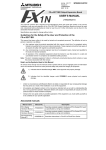
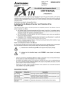
FX1N-2EYT-BD Output Expansion Board
USER’S MANUAL
JY992D95201A
This manual contains text, diagrams and explanations which will guide the reader in the correct
installation, safe use and operation of the FX1N-2EYT-BD Output Expansion Board and should be read
and understood before attempting to install or use the unit. Further information can be found in the
associated manuals list below.
2. Installation
The FX1N-2EYT-BD output expansion board (hereafter referred to as "FX1N-2EYT-BD" or "Function
expansion board") is a function expansion board to be installed in the FX1S or FX1N series programmable
controller (hereafter referred to as "PLC"), to increase the output of two points.
1.1 Features of the FX1N-2EYT-BD
1) Additional increase of two output points.
2) Internal mounting in the top of the PLC meaning no need for change to the installation area of the
PLC.
3) Additional outputs have special auxiliary relays associated to each point, which are turned ON or OFF
depending on the required output state of the FX1N-2EYT-BD.
As special auxiliary relays are used in the PLC program for the output points, the additional outputs
are not included in the regular system I/O count.
1.2 External Dimensions and Each Part Name
Specifications are subject to change without notice
2 )
This manual has been written to be used by trained and competent personnel. The definition of such a
person or persons is as follows:
Accessories : Top cover for board 1
M3 screw to mount board 2
M3 screw to fix top cover 1
3 )
1 )
B Y 0 -
3 8 .5 (1 .5 2 ")
B Y 0 +
B Y 1 +
a) Any engineer using the product associated with this manual, should be of a competent nature,
trained and qualified to the local and national standards. These engineers should be fully aware of
all aspects of safety with regards to automated equipment.
B Y 1 -
2 )
b) Any commissioning or service engineer must be of a competent nature, trained and qualified to
the local and national standards.
5 )
4 )
c) All operators of the completed equipment should be trained to use that product in a safe and
coordinated manner in compliance to established safety practices.
1) Do not use the function expansion board in environments that contain excessive or
conductive dust, corrosive or flammable gas, moisture or rain, excessive heat, regular
impact shocks or excessive vibration.
Use in these environment may cause electric shock, fire, malfunction, damage or
deterioration of the product.
2) Cut off all phases of power source before installing / removing or performing wiring work
on the unit in order to avoid electric shock or damage of product.
3) After the installation wiring etc. replace the PLCs top cover before power ON.
4) Securely install the function expansion board, and fix it to the PLC.
Defective contact can cause malfunction.
2.1 Mounting
Dimensions: mm (inches)
4 3 (1 .6 9 ")
Guidelines for the Safety of the User and Protection of the
FX1N-2EYT-BD.
Caution
1) Output terminal.
l
: Unused (Do not wire).
BY0+ : + side terminal of output BY0
BY0- : - side terminal of output BY0
BY1+ : + side terminal of output BY1
BY1- : - side terminal of output BY1
The top face of this connector is higher than the top face of
the PLC panel cover by approximately 7 mm.
Turn off all power to the PLC before installing the FX1N-2EYT-BD.
a) Top cover for FX1N-2EYT-BD (supplied as an accessory))
b) M3 screw to fix top cover (supplied as an accessory)
c) M3 screw to fix FX1N-2EYT-BD (2 pieces)
(supplied as accessories)
d) External port for optional equipment
b )
c )
e )
c )
e) FX1N-2EYT-BD (function expansion board)
Note: Do not remove this screw on the PLC(FX1S).
d )
2) Mounting hole (2-φ3.5(0.14"))
Note: The term ‘completed equipment’ refers to a third party constructed device which contains or uses
the product associated with this manual.
a )'
a )
N o te )
Note’s on the Symbols Used in this Manual
3) Output LED
BY0 LED : The LED lights when BY0 is turn on.
BY1 LED : The LED lights when BY1 is turn on.
At various times through out this manual certain symbols will be used to highlight points of information
which are intended to ensure the users personal safety and protect the integrity of equipment.
4) External port for display module FX1N-5DM or memory cassette
FX1N-EEPROM-8L
3) Fix the function expansion board to the main unit with two M3 screws c).
(Tightening torque: 0.3 to 0.6 Nžm)
5) External connector for PLC
4) Attach the top cover for FX1N-2EYT-BD a) in place of the original cover.
During attachment, remove a)’ with a suitable tool, so that the output terminals are exposed.
1) Indicates that the identified danger WILL cause physical and property damage.
1.3 System configuration
2) Indicates that the identified danger could POSSIBLY cause physical and property
damage.
•
Under no circumstances will Mitsubishi Electric be liable or responsible for any consequential damage
that may arise as a result of the installation or use of this equipment.
•
All examples and diagrams shown in this manual are intended only as an aid to understanding the
text, not to guarantee operation. Mitsubishi Electric will accept no responsibility for actual use of the
product based on these illustrative examples.
•
Owing to the very great variety in possible application of this equipment, you must satisfy yourself as
to its suitability for your specific application.
Associated manuals
Manual No.
Description
FX1S Series
Hardware Manual
Manual name
JY992D83901
Describes contents related to hardware of FX1S Series PLC such
as specifications, wiring and installation.
FX1N Series
Hardware Manual
JY992D89301
Describes contents related to hardware of FX1N Series PLC such
as specifications, wiring and installation.
FX Programming
Manual II
JY992D88101
Describes instructions in FX1S/FX1N/FX2N/FX2NC Series.
1) Remove the top cover of the main unit and keep.
2) Plug FX1N-2EYT-BD e) in to the external port d).
5) Fix the top cover with an M3 screw b). (Tightening torque: 0.3 to 0.6 Nžm)
•
Only one function expansion board can be used on one FX1S and FX1N series PLC main unit.
Do not try to install two or more expansion boards.
•
FX1N-2EYT-BD can be used together with FX1N-5DM.
Refer to the FX1S or FX1N HARDWARE MANUAL when using the FX1N-2EYT-BD together with an
FX 1N-5DM.
•
When using with the memory cassette FX1N-EEPROM-8L, only program transfer is possible.
(The memory cassette cannot be connected permanently)
1.4 Applicable PLC
Series name
Applicable version
FX1S
V2.0 or later
FX1N
V2.0 or later