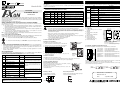
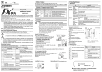
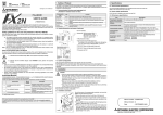
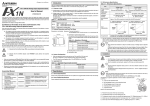
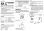
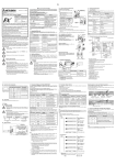
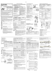
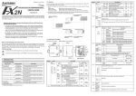
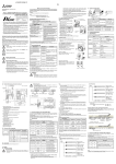
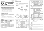
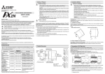
1
Side
Side
A JAPANESE
B ENGLISH
FX0N-485ADP
Installation Manual
1. Outline of Product
4. Product Specification
The 485ADP is an insulated RS-485 communication adapter with an Terminal block for connecting RS485 equipment.
Connected to the main unit of the FX Series PLC, it enables signal exchange between the PLC and
equipment via an RS-485 port.
4.1 Specification
2. Communication Functions and Applicable PLC
(Available in indicated version or later)
Communication
type
FX0N
FX1N
FX1S
N:N network
This manual contains text, diagrams and explanations which will guide the reader in the correct installation,
safe use and operation of the FX0N-485ADP (hereafter abbreviated to "485ADP") and should be read and
understood before attempting to install or use the unit. Further information can be found in the associated
manuals mentioned below.
Specifications are subject to change without notice
Safety guidelines for the user and protection of the FX0N-485ADP.
This manual has been written to be used by trained and competent personnel. The definition of such a
person or persons is as follows:
a) Any engineer using the product associated with this manual, should be of a competent nature,
trained and qualified to the local and national standards. These engineers should be fully aware of
all aspects of safety with regards to automated equipment.
b) Any commissioning or service engineer must be of a competent nature, trained and qualified to the
local and national standards.
c) All operators of the completed equipment should be trained to use this product in a safe and
coordinated manner in compliance to established safety practices.
Note: The term ‘completed equipment’ refers to a third party constructed device which contains or uses the
product associated with this manual.
FX2NC
V2.00
First
product
V2.00
First
product
Data transfer connecting up to eight FX Series PLCs.
Parallel link
V1.20
First
product
V1.04
First
product
Data transfer between two PLCs relationship specifying
master/slave station.
Computer link
V1.20
First
product
V1.06
First
product
Data transfer via link protocol between PLC and
computer (specified as the master station).
No protocol
communication
V1.20
First
product
V1.06
First
product
Serial communication without protocol between PLC
and equipment via RS-485 interface.
Inverter
communication
—
—
V3.00
V3.00
Function
3.1 How to Install to FX Series PLC
Installation to FX1S/FX1N/FX2N
Turn OFF the PLC before beginning any work.
•
•
•
Under no circumstances will Mitsubishi Electric be liable or responsible for any consequential damage
that may arise as a result of the installation or use of this equipment.
All examples and diagrams shown in this manual are intended only as an aid to understanding the text,
not to guarantee operation. Mitsubishi Electric will accept no responsibility for the actual use of the
product based on these illustrative examples.
Please contact a Mitsubishi distributor for more information concerning applications in life critical
situations or high reliability.
Associated Manuals
PROGRAMMING MANUAL, PROGRAMMING MANUAL ΙΙ, or FX COMMUNICATION USER'S MANUAL
mentioned below are not provided in sets with a product.
Contact our agent where the product was purchased to request the manuals accordingly.
Manual Name
This
FX0N-485ADP INSTALLATION
manual MANUAL
Manual
Number
JY992D53101
★
FX COMMUNICATION USER'S
MANUAL
JY992D69901
✩
FX1S HARDWARE MANUAL
JY992D83901
✩
FX0/FX0N HARDWARE MANUAL
JY992D47501
Description
Describes contents related to installation of the
FX0N-485ADP Module.
Describes contents related to communication
available in FX Series PLC such as wiring,
communication setting, and program examples.
✩
FX1N HARDWARE MANUAL
JY992D89301
✩
FX2N HARDWARE MANUAL
JY992D66301
✩
FX2NC HARDWARE MANUAL(DSS/DS)
(D/UL)
JY992D76401
JY992D87201
✩
PROGRAMMING MANUAL
JY992D76401
Describes contents related to instruction in FX0/
FX0S/FX0N/FX/FX2/FX2C Series PLC.
JY992D88101
Describes contents related to instruction in FX1S/
FX1N/FX2N/FX2NC Series PLC.
✩
PROGRAMMING MANUAL ΙΙ
✩
FX1N-CNV-BD
Special Adapter Connection Board
JY992D84701
✩
FX2N-CNV-BD
Special Adapter Connection Board
JY992D63601
★ Indispensable manual
Describes contents related to installation of the
each board.
N:N network: 384000 bps, Parallel link: 19200bps
Computer link, No protocol: 300/600/1200/2400/4800/9600/19200 bps
N:N network, Parallel link
Computer (dedicated protocol: format 1/format 4), No protocol
Baud rate
Communication
format
LED display
(LED color)
Power: green, RD: red, SD: red
Corresponding model
FX1N-CNV-BD
FX1N, FX1S
FX2N-CNV-BD
FX2N
1) Top cover
2) POWER LED
Li g h t i ng w h i le p owe r i s c o r r e c t l y
supplied.
3) RD LED
Lighting while receiving data.
4) SD LED
Lighting while sending data.
5) Extension cable
6) Direct mounting hole
7) DIN rail mounting slot
(DIN rail width :35 (1.37"))
8) DIN rail mounting clip
Unit : mm(inches)
2-φ4.5(0.18)
1)
6)
2)
3)
7)
4)
8)
9(0.35)
87(3.43)
4(0.16)
43(1.69)
Weight:
Approx. 0.3 kg (0.66 lbs)
Color:
Munsell 0.08GY 7.64/0.81
DIN rail width: 35 mm (1.37")
Accessories: Terminal resistors (330 Ω x 2 and 110 Ω x 1),
Station number label for linking
Y0
The terminal configuration of the RS-485 port on the 485ADP is as shown below.
Y2
Y1
2)
1)
2)
4) Fix the above board using the M3 screws supplied.
Tightening torque: 0.3 to 0.6 N·m
5) Connect the in-built cable of the 485ADP to the port on the
board from the left side.
3)
1)
Installation to
FX0N/FX2NC
(FX2NC in the
diagram)
2)
8)
Installation to FX0N/FX2NC
Turn OFF the PLC before beginning any work.
1) Remove the cover of the port for a special adapter provided on the left side of the main unit.
2) Connect the in-built cable of the 485ADP to the port for a special adapter.
3.2 How to Install to Panel Face
FX Series PLC
Directly fix to the panel face using 2 sets of a screw (M4), a spring
washer, and a flat washer in the mounting holes.
Tightening torque: 0.7 to 1.0 N·m
For the pitch and positions of mounting screw holes, refer to the
external dimensions.
7)
4)
5)
1)
2)
3)
4)
5)
6)
7)
8)
24+ terminal . . . .Power supply terminal (M3 screw)
24G terminal. . . .Power supply terminal (M3 screw)
FG terminal . . . .Frame ground (M3 screw)
SDA terminal . . .Data transmission terminal (M3 screw)
SDB terminal . . .Data transmission terminal (M3 screw)
LINK SG . . . . . . .Signal ground (M3 screw)
RDB terminal . . .Data transmission terminal (M3 screw)
RDA terminal . . .Data transmission terminal (M3 screw)
6)
Terminals screws of terminal block for RS-485 are M3 threaded. Therefore, connect wiring by fitting a
crimped terminal suited to the terminal screws (see below) to the cable.
Tightening torque of terminals is 0.5 to 0.8 N·m. Screw terminals must be secure enough to prevent a
loose connection from causing a malfunction.
M 3 th re a d s
6 .2 m m
( 0 .2 4 in c h e s )
o r le s s
Screws
M 3 th re a d s
6 .2 m m
( 0 .2 4 in c h e s )
o r le s s
FX0N-485ADP
Mounting on DIN rail
Dismounting from DIN rail
Fix the 485ADP to the DIN rail,
DIN46277 (35 mm (1.37") wide).
Slightly pull down the DIN rail mounting clip using a
tool such as a slotted screwdriver.
Manual number : JY997D53101
Manual revision : D
Date
: September 2003
DIN rail
FX0NFX Seeries
485ADP PLC
5)
4.3 Terminal configuration and terminal screws
X3
X1
3)
5)
✩ Either manual is necessary.
This manual describes the installation the and specifications of the 485ADP.
For details on wiring (including use of terminal resistor and preparation of cable) with communication equipment,
system configuration and communication setting, and program examples, refer to the "FX COMMUNICATION USER'S
MANUAL".
Photo-coupler isolation
Total extension distance: 500 m or less
(50 m or less if FX2N-485-BD or FX1N-485-BD is installed in connected equipment)
4)
Direct installation to the panel face
Describes contents related to hardware of FX
Series PLC such as specifications, wiring, and
installation.
Conforming to RS-485/RS-422
Type of isolation
Transmission
distance
Installation to
FX1S/FX1N/FX2N
(FX2N in the
diagram)
1)
1) Remove the panel cover from the top face of the main unit.
2) Take off the resin cover from the left side of the main unit.
3) Install the following board to the port on the main unit.
Board name
Transmission
standard
4.2 Outside Dimensions and Part Names
• Use in the environments specified under the general specification in the manual.
Do not use the product in environments with excessive or conductive dust, corrosive or
flammable gas, oily smoke, moisture or rain, excessive heat, regular impact shocks or
excessive vibration, as it may result in electrical shock, fire, malfunction, damage or
deterioration on the product.
• Make sure to shut off the power outside the product before installing or wiring it.
Otherwise, electric shock or serious damage to the product may occur.
• Never drop wire chips or shavings into the vent slits when drilling screw holes or performing
wiring, as they may cause fire, breakdown, or malfunction.
• Securely install the 485ADP to the designated port.
Poor connection may cause malfunction.
1) Indicates that the identified danger WILL cause physical and property damage.
5 V DC (supplied from PLC main unit) max. 30 mA
24 V DC (supplied from External power supply) max. 50 mA
Number of occupied
0 point (unrelated to maximum number of controlled points of the PLC)
I/O points
Performance
Communication
specification
Half-duplex
method
Controlling Mitsubishi's FREQROL inverter using
EXTR instruction in function expansion memory.
Caution
At various times throughout this manual certain symbols will be used to highlight points of information which
are intended to ensure the users personal safety and protect the integrity of equipment.
Specification
500 V AC, 1 min (Between all terminals in batch and FG terminal)
General
specification Insulation resistance 5 MΩ or more, 500 V DC by Megger
(Between all terminals in batch and FG terminal)
3. Installation
Notes on the Symbols Used in this Manual
2) Indicates that the identified danger could POSSIBLY cause physical and property damage.
Item
Withstand voltage
Power supply Power supply
specification voltage, current
FX2N
JY992D53101D
All other specifications than the followings are equivalent to those of the FX Series PLC main unit.
90(3.54)
B
80(3.15)
Side
Detach
HEAD OFFICE : MITSUBISHI DENKI BLDG MARUNOUTI TOKYO 100-8310
HIMEJI WORKS : 840, CHIYODA CHO, HIMEJI, JAPAN
Side
Side
A JAPANESE
B ENGLISH
FX0N-485ADP
Installation Manual
1. Outline of Product
4. Product Specification
The 485ADP is an insulated RS-485 communication adapter with an Terminal block for connecting RS485 equipment.
Connected to the main unit of the FX Series PLC, it enables signal exchange between the PLC and
equipment via an RS-485 port.
4.1 Specification
2. Communication Functions and Applicable PLC
(Available in indicated version or later)
Communication
type
FX0N
FX1N
FX1S
N:N network
This manual contains text, diagrams and explanations which will guide the reader in the correct installation,
safe use and operation of the FX0N-485ADP (hereafter abbreviated to "485ADP") and should be read and
understood before attempting to install or use the unit. Further information can be found in the associated
manuals mentioned below.
Specifications are subject to change without notice
Safety guidelines for the user and protection of the FX0N-485ADP.
This manual has been written to be used by trained and competent personnel. The definition of such a
person or persons is as follows:
a) Any engineer using the product associated with this manual, should be of a competent nature,
trained and qualified to the local and national standards. These engineers should be fully aware of
all aspects of safety with regards to automated equipment.
b) Any commissioning or service engineer must be of a competent nature, trained and qualified to the
local and national standards.
c) All operators of the completed equipment should be trained to use this product in a safe and
coordinated manner in compliance to established safety practices.
Note: The term ‘completed equipment’ refers to a third party constructed device which contains or uses the
product associated with this manual.
FX2NC
V2.00
First
product
V2.00
First
product
Data transfer connecting up to eight FX Series PLCs.
Parallel link
V1.20
First
product
V1.04
First
product
Data transfer between two PLCs relationship specifying
master/slave station.
Computer link
V1.20
First
product
V1.06
First
product
Data transfer via link protocol between PLC and
computer (specified as the master station).
No protocol
communication
V1.20
First
product
V1.06
First
product
Serial communication without protocol between PLC
and equipment via RS-485 interface.
Inverter
communication
—
—
V3.00
V3.00
Function
3.1 How to Install to FX Series PLC
Installation to FX1S/FX1N/FX2N
Turn OFF the PLC before beginning any work.
•
•
•
Under no circumstances will Mitsubishi Electric be liable or responsible for any consequential damage
that may arise as a result of the installation or use of this equipment.
All examples and diagrams shown in this manual are intended only as an aid to understanding the text,
not to guarantee operation. Mitsubishi Electric will accept no responsibility for the actual use of the
product based on these illustrative examples.
Please contact a Mitsubishi distributor for more information concerning applications in life critical
situations or high reliability.
Associated Manuals
PROGRAMMING MANUAL, PROGRAMMING MANUAL ΙΙ, or FX COMMUNICATION USER'S MANUAL
mentioned below are not provided in sets with a product.
Contact our agent where the product was purchased to request the manuals accordingly.
Manual Name
This
FX0N-485ADP INSTALLATION
manual MANUAL
Manual
Number
JY992D53101
★
FX COMMUNICATION USER'S
MANUAL
JY992D69901
✩
FX1S HARDWARE MANUAL
JY992D83901
✩
FX0/FX0N HARDWARE MANUAL
JY992D47501
Description
Describes contents related to installation of the
FX0N-485ADP Module.
Describes contents related to communication
available in FX Series PLC such as wiring,
communication setting, and program examples.
✩
FX1N HARDWARE MANUAL
JY992D89301
✩
FX2N HARDWARE MANUAL
JY992D66301
✩
FX2NC HARDWARE MANUAL(DSS/DS)
(D/UL)
JY992D76401
JY992D87201
✩
PROGRAMMING MANUAL
JY992D76401
Describes contents related to instruction in FX0/
FX0S/FX0N/FX/FX2/FX2C Series PLC.
JY992D88101
Describes contents related to instruction in FX1S/
FX1N/FX2N/FX2NC Series PLC.
✩
PROGRAMMING MANUAL ΙΙ
✩
FX1N-CNV-BD
Special Adapter Connection Board
JY992D84701
✩
FX2N-CNV-BD
Special Adapter Connection Board
JY992D63601
★ Indispensable manual
Describes contents related to installation of the
each board.
N:N network: 384000 bps, Parallel link: 19200bps
Computer link, No protocol: 300/600/1200/2400/4800/9600/19200 bps
N:N network, Parallel link
Computer (dedicated protocol: format 1/format 4), No protocol
Baud rate
Communication
format
LED display
(LED color)
Power: green, RD: red, SD: red
Corresponding model
FX1N-CNV-BD
FX1N, FX1S
FX2N-CNV-BD
FX2N
1) Top cover
2) POWER LED
Li g h t i ng w h i le p owe r i s c o r r e c t l y
supplied.
3) RD LED
Lighting while receiving data.
4) SD LED
Lighting while sending data.
5) Extension cable
6) Direct mounting hole
7) DIN rail mounting slot
(DIN rail width :35 (1.37"))
8) DIN rail mounting clip
Unit : mm(inches)
2-φ4.5(0.18)
1)
6)
2)
3)
7)
4)
8)
9(0.35)
87(3.43)
4(0.16)
43(1.69)
Weight:
Approx. 0.3 kg (0.66 lbs)
Color:
Munsell 0.08GY 7.64/0.81
DIN rail width: 35 mm (1.37")
Accessories: Terminal resistors (330 Ω x 2 and 110 Ω x 1),
Station number label for linking
Y0
The terminal configuration of the RS-485 port on the 485ADP is as shown below.
Y2
Y1
2)
1)
2)
4) Fix the above board using the M3 screws supplied.
Tightening torque: 0.3 to 0.6 N·m
5) Connect the in-built cable of the 485ADP to the port on the
board from the left side.
3)
1)
Installation to
FX0N/FX2NC
(FX2NC in the
diagram)
2)
8)
Installation to FX0N/FX2NC
Turn OFF the PLC before beginning any work.
1) Remove the cover of the port for a special adapter provided on the left side of the main unit.
2) Connect the in-built cable of the 485ADP to the port for a special adapter.
3.2 How to Install to Panel Face
FX Series PLC
Directly fix to the panel face using 2 sets of a screw (M4), a spring
washer, and a flat washer in the mounting holes.
Tightening torque: 0.7 to 1.0 N·m
For the pitch and positions of mounting screw holes, refer to the
external dimensions.
7)
4)
5)
1)
2)
3)
4)
5)
6)
7)
8)
24+ terminal . . . .Power supply terminal (M3 screw)
24G terminal. . . .Power supply terminal (M3 screw)
FG terminal . . . .Frame ground (M3 screw)
SDA terminal . . .Data transmission terminal (M3 screw)
SDB terminal . . .Data transmission terminal (M3 screw)
LINK SG . . . . . . .Signal ground (M3 screw)
RDB terminal . . .Data transmission terminal (M3 screw)
RDA terminal . . .Data transmission terminal (M3 screw)
6)
Terminals screws of terminal block for RS-485 are M3 threaded. Therefore, connect wiring by fitting a
crimped terminal suited to the terminal screws (see below) to the cable.
Tightening torque of terminals is 0.5 to 0.8 N·m. Screw terminals must be secure enough to prevent a
loose connection from causing a malfunction.
M 3 th re a d s
6 .2 m m
( 0 .2 4 in c h e s )
o r le s s
Screws
M 3 th re a d s
6 .2 m m
( 0 .2 4 in c h e s )
o r le s s
FX0N-485ADP
Mounting on DIN rail
Dismounting from DIN rail
Fix the 485ADP to the DIN rail,
DIN46277 (35 mm (1.37") wide).
Slightly pull down the DIN rail mounting clip using a
tool such as a slotted screwdriver.
Manual number : JY997D53101
Manual revision : D
Date
: September 2003
DIN rail
FX0NFX Seeries
485ADP PLC
5)
4.3 Terminal configuration and terminal screws
X3
X1
3)
5)
✩ Either manual is necessary.
This manual describes the installation the and specifications of the 485ADP.
For details on wiring (including use of terminal resistor and preparation of cable) with communication equipment,
system configuration and communication setting, and program examples, refer to the "FX COMMUNICATION USER'S
MANUAL".
Photo-coupler isolation
Total extension distance: 500 m or less
(50 m or less if FX2N-485-BD or FX1N-485-BD is installed in connected equipment)
4)
Direct installation to the panel face
Describes contents related to hardware of FX
Series PLC such as specifications, wiring, and
installation.
Conforming to RS-485/RS-422
Type of isolation
Transmission
distance
Installation to
FX1S/FX1N/FX2N
(FX2N in the
diagram)
1)
1) Remove the panel cover from the top face of the main unit.
2) Take off the resin cover from the left side of the main unit.
3) Install the following board to the port on the main unit.
Board name
Transmission
standard
4.2 Outside Dimensions and Part Names
• Use in the environments specified under the general specification in the manual.
Do not use the product in environments with excessive or conductive dust, corrosive or
flammable gas, oily smoke, moisture or rain, excessive heat, regular impact shocks or
excessive vibration, as it may result in electrical shock, fire, malfunction, damage or
deterioration on the product.
• Make sure to shut off the power outside the product before installing or wiring it.
Otherwise, electric shock or serious damage to the product may occur.
• Never drop wire chips or shavings into the vent slits when drilling screw holes or performing
wiring, as they may cause fire, breakdown, or malfunction.
• Securely install the 485ADP to the designated port.
Poor connection may cause malfunction.
1) Indicates that the identified danger WILL cause physical and property damage.
5 V DC (supplied from PLC main unit) max. 30 mA
24 V DC (supplied from External power supply) max. 50 mA
Number of occupied
0 point (unrelated to maximum number of controlled points of the PLC)
I/O points
Performance
Communication
specification
Half-duplex
method
Controlling Mitsubishi's FREQROL inverter using
EXTR instruction in function expansion memory.
Caution
At various times throughout this manual certain symbols will be used to highlight points of information which
are intended to ensure the users personal safety and protect the integrity of equipment.
Specification
500 V AC, 1 min (Between all terminals in batch and FG terminal)
General
specification Insulation resistance 5 MΩ or more, 500 V DC by Megger
(Between all terminals in batch and FG terminal)
3. Installation
Notes on the Symbols Used in this Manual
2) Indicates that the identified danger could POSSIBLY cause physical and property damage.
Item
Withstand voltage
Power supply Power supply
specification voltage, current
FX2N
JY992D53101D
All other specifications than the followings are equivalent to those of the FX Series PLC main unit.
90(3.54)
B
80(3.15)
Side
Detach
HEAD OFFICE : MITSUBISHI DENKI BLDG MARUNOUTI TOKYO 100-8310
HIMEJI WORKS : 840, CHIYODA CHO, HIMEJI, JAPAN