1
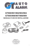
GT613 - 614 - 615 FITTING INSTRUCTIONS
Correct alarm positioning for the shock sensor
It is advisable to place the alarm as
indicated in the figure to obtain the
maximum of performances by the
shock sensor. Note that the maximum
sensitivity is obtained with a 30°
angulation.
SHOCK SENSOR
MINIMUM SENSITIVITY
70 degrees
SHOCK SENSOR M
AXIMUM SENSIITIVITY
WARNING: Incorrect installation will
increase the risk of water ingress
into the siren.
Make sure that the loom cover is
attached with supplied screws and
the sheath covers the neck of the
loom cover and secured with a cable
tie.
Tilt sensor adjustment
clockwise = more sensitive
anti-clockwise = less sensitive
(use the supplied screwdriver)
30 degrees
YELLOW/BLACK (RELAY OUTPUT)
CHECK LED
RED
BLACK
BLACK (RELAY COMMON)
15 AMP FUSE
+12V
Constant or intermittent output when the alarm is
being triggered (current max. 5A). With this wire it
is possible to drive the HORN relay, an electronic
siren (GT43) the parking lights or a after market satellite
system.
Connect to positive or negative depending on the
polarity required on the YELLOW/BLACK wire.
BOOT/BONNET
PIN SWITCH
RED
ORIGINAL DOOR
PINSWITCH
+12V
GREEN
BROWN
GREEN/BROWN
EARTH
BATTERY
Positive output when the
alarm is armed
Additional sensors/modules
or satellite system
(current max. 80mA)
PINK
GREEN/BLACK
IGNITION KEY
GT431
YELLOW
+15/54
IGNITION SWITCHED LIVE
GT431
WHITE
-
To the GREEN/BLACK wire
on additional sensors/modules
GT632
RED
+
BROWN
+15/54
30
PINK
STARTER MOTOR*
IMMOBILISATION
86
RED/GREY
87
Diode 1N4007
CUT
87A
GREY/BLACK
M
ORANGE
85
Additional relay
NEGATIVE command for the starter
immobilisation (current max 80mA)
Connect to either near side or
off side indicator wire
* NOTE: it is possible to use the GT465 module
POSITIONING OF THE
GT431 ULTRASONIC SENSORS
WHITE
RED
POSITIONING OF THE GT 632
HYPERFREQUENCY SENSOR
TRANSMITTING
SIDE
ADJUSTMENT
LED
SENSITIVITY
ADJUSTMENT
VEHICLE
INDICATORS
CONTROL UNIT
GREEN/BLACK
GT431
-
+
ADJUSTMENT
TRIMMER
ABOVE THE DASHBOARD INCORRECT POSITIONS
DASHBOARD
CORRECT
POSITIONS
CENTRE
CONSOLE
GT613UKRev02.p65
1
INSTALLATION MANUAL - GT613 ELECTRICAL CONNECTIONS
1. Complete a pre-installation check and disconnect the negative terminal of the vehicle’s battery.
2. Mount the alarm in the bonnet compartment away from direct source of water spray and humidity.
3. Connect the BROWN wire to original negative vehicle’s wire.
4. Connect the RED wire to permanent positive supply.
5. Connect the PINK wire to the PINK wire of additional sensors (i.e. the hyperfrequency sensor or the ultrasonics
module) and/or the after market satellite system. Maximum current: 80 mA.
6. Connect the GREEN/BLACK wire to the GREEN/BLACK wire of additional sensors.
7. The YELLOW wire is the ignition switched live (+15/54). Connect to an ignition switched live that remains live
even when the engine is being cranked. Do not connect the YELLOW wire to the load side of the engine
immobilisation cut.
Cut one of the indicator output wires from the vehicle alarm unit.
8. Connect the ORANGE wire to the indicator side of the cut.
9. Connect the RED/GREY to the control unit side of the cut wire. The correct connection of the ORANGE
wires and RED/GREY wires is most important for the alarm operation and of the vehicle’s indicators
operatioN. Warning: The emergency indicators (HAZARD) activation doesn’t allow the alarm arming
and disarming.
10. Connect the GREEN wire to the original boot and bonnet pin switches, provided that they are switched earth
only.
11. Connect the GREEN/BROWN wire to the original vehicle’s door pin switches, provided that they are switched
earth only.
12. Connect the GREY/BLACK wire to additional relay for immobilisation on either diesel or petrol vehicles.
13. The YELLOW/BLACK wire is the positive or negative output command selectable by the BLACK wire when
the alarm triggers. It can be used to command the horn directly, electronic sirens, parking lights or satellite
installations. Maximum Current 5A. The command is selectable, constant or intermittent by dip switches (refer to
the table 1). It is advisable: intermittent for the horn or parking lights, constant for electronic sirens or satellite
installation.
14. The BLACK wire is the common for the YELLOW/BLACK wire. Connect it to positive for positive command or
negative for negative command.
15. Place the CHECK LED on the dashboard and insert it in the connector situated on the alarm loom. It is the user
interface for all the alarm signallings.
GT431 ULTRASONICS SENSOR CONNECTIONS (for GT614 only)
1. Position the module in the passenger’s compartment and ensure that it is located away from direct sources of
water spray and humidity.
2. Connect the BROWN wire to the original vehicle negative wire.
3. Connect the PINK wire to the PINK wire of the alarm.
4. Connect the GREEN/BLACK wire to the GREEN/BLACK wire of the alarm.
5. Install the two ultrasonic sensors (RED transmitting ) and (WHITE receiving) at the top of the “A” pillars. One
either side of the windscreen pointing towards an hypothetical point at the centre of the rear screen and ensure
that there are no objects (i.e. headrest) blocking their view. Plug the ultrasonics connectors in the module paying
attention to their colours: RED to the right and WHITE to the left (see diagram on page 1). Do not cut or lengthen the
ultrasonic cables.
GT632 HYPERFREQUENCY SENSOR CONNECTIONS (for GT615 only)
1. Position the module as indicated on page 1 “POSITIONING OF THE GT 632 HYPERFREQUENCY SENSOR”.
2. Connect the BROWN wire to the original vehicle negative wire.
3. Connect the PINK wire to the PINK wire of the alarm.
4. Connect the GREEN/BLACK wire to the GREEN/BLACK wire of the alarm.
For a correct operation the module must be installed in the passenger’s compartment behind the the centre
console with the transmitting side pointing towards the rear seats slightly turn towards the roof. Only for the
cabriolet vehicles it is advisable to install the module under the centre console (near the gear lever or the hand
brake) with the transmitting side pointing towards the roof.
NOTE: To improve the module performances is however advisable to check the optimum position for each type of
vehicle.
The module must not be mounted in the following positions:
a. on the dashboard b. on the roof pointing towards the floor c. near the glove compartment containing metal
objects (coins. keys, etc.) d. under metal.
FUNCTIONS SELECTABLE BY THE DIP SWITCH
With the dip switches situated near the alarm connector, it is posible to programme the alarm functions (see table
below). The settings must be carried out when the alarm is disarmed and they will have immediate effect. The factory
default setting is OFF.
TABLE 1 (SELECTABLE FUNCTIONS BY THE DIP SWITCH)
ALARM FUNCTIONS
NUMBER OF
DIP SWITCHES
DIP SWITCH POSITION
OFF
ON
Acoustic signal when
arming/disarming the alarm
1
Isolated
Inserted
Self-coding
2
Isolated
Enabled
Rapid test
3
Isolated
Enabled
YELLOW/BLACK wire output
4
Intermittent
Constant
EXPLANATIONS OF SELECTABLE ALARM FUNCTIONS BY THE DIP SWITCH
(1) Acoustic signal function when arming/disarming the alarm
With this function it is possible to have an acoustic signal “beep” when arm/disarm.
(4) YELLOW/BLACK wire output:
With this function it is possible to have a constant or an intermittent YELLOW/BLACK wire when arming or
disarming. Intermittent for the horn or parking lights, constant for the siren or after market satellite system.
DOORS LOCK/UNLOCK IMPULSES SELF-CODING PROCEDURE
To carry out the lock/unlock impulses self-coding ensure that:
• The RED/GREY and ORANGE wires are connected as indicated in the diagram of page 1.
• All the doors (and the hatckback) aret closed but with the safety catches on.
• The ignition key is OFF (check that there is any voltage).
When the check has been completed, proceed as follows:
(a) move the dip switch No2 to the ON position and wait 3 seconds; the alarm will emit 6 acoustic signals to
indicate that it is in the condition to self-code the doors lock command impulses (arming) and unlock (disarming);
when the check LED starts to flash it is possible to proceed with the points (b) and (c).
(b) press the original doors remote control handset locking button, after a couple of seconds the alarm will emit
1 short acoustic signal.
(c) press the original doors remote control handset unlocking button after a couple of seconds, the alarm will emit
2 short acoustic signals.
WARNING: If IMPULSES SELF-CODING PROCEDURE has not been completed correctly, the alarm will emit a long
acoustic beep and the check LED will switch off; move the dip switch No2 to position OFF. Repeat the procedure
from point (a).
NOTE: At any time you need to reprogramme the lock/unlock impulses, i.e. in case the connection of the system
command wires (RED/GREY and ORANGE) has to be arranged, it is necessary to carry out the procedure from
point (a).
GT613UKRev02.p65
2
EMERGENCY DISARMING FUNCTION
If self-coding operation has been incorrectly carried out and the alarm is armed, proceed with the following:
(a) Open and leave the door open. The alarm will sound.
(b) Switch the vehicle’s ignition ON and then OFF as many times as indicated in the GT CARD CODE (every
operation needs to be carried out within 5 seconds)
(c) Wait 10 seconds without carrying out any operation; if the procedure has been carried out correctly the alarm will
disarm and the check LED switches off. Before using the vehicle’s original handset, repeat the self-coding procedure.
INSTALLATION CHECK (TEST)
Ensure that the boot, all the doors and the bonnet are closed and the ignition key is switched off.
At this point proceed as follows:
(a) move the dip switch No3 to the ON position and wait for three seconds; the alarm will emit 3 acoustic signals to
indicate that it is in the TEST condition.
If the alarm has been installed correctly the following will occur:
(b) The PINK wire will have a +12V positive supply and the additional sensors/modules connected to this wire
will be activate.
(c) When opening one of the doors (GREEN/BROWN wire) and/or the boot/bonnet (GREEN wire) you will have an
acoustic signal (beep).
(d) The activation of an additional sensor (GREEN/BLACK wire) you will have a visual signal (check LED) and an
acoustic signal (beep).
(e) When the ignition key is ON the incorporated siren in the alarm sounds for approximately 1 second.
If fitting the GT 613 go to paragraph “SHOCK SENSOR OPERATION”, if any otherotherwise you have to adjust to
the minimum the shock sensor sensitivity (turning the adjuster situated near the GT 613 connector with the
supplied screwdriver anticlockwise) to avoid the interferences of the same sensor with the tests of the
additional sensors.
GT431 ULTRASONICS SENSOR OPERATION TEST (if installed)
Remove all possible items that may create a false alarm through movement inside the vehicle. Close all the doors
and windows leaving just enough room through one window to introduce a hand/arm. Put your arm through the
gap and move it around. The alarm will trigger. Sensitivity increases if you turn the adjuster clockwise and
decreases if you turn the screw anticlockwise. NOTE: This operation is important not to have false alarms. To
check that it is not oversensitive, thump the front and rear windows with your hand (care should be taken not do
damage the windows). The alarm should not be triggered by this thumping.
GT 632 HYPERFREQUENCY SENSOR OPERATION TEST (if installed)
Remove any items that may create false alarm through movement inside the vehicle. Close the doors but leave
just enough room through each window to introduce an arm. “Set” the alarm and wait for a few minutes.
Introduce your arm through the gap and move it around. The microwave trigger LED will illuminate and the alarm
will activate. To increase the microwave senor sensitivity turn the adjuster clockwise. Beware that it is possible
to increase sensitivity to a point at which it will become too sensitive and may cause false alarms.
WARNING: This procedure is one of the most important for correct alarm operation. To check that the
hyperfrequency is not over sensitive, move your arms across the outside of the windows and the soft top
roof (if the vehicle is cabriolet). This should not trigger the alarm.
NOTE: only the introduction of an object should trigger the alarm, therefore it is possible to leave the roof open
without causing false alarms.
FINAL OPERATIONS
Carry out a siren test checking that the siren operates correctly.
BOOT/BONNET PIN SWITCHES
The impulse generated by opening the boot or the bonnet is detected by the alarm and causes it to activate.
DOORS PIN SWITCHES, SHOCK SENSOR AND ADDITIONAL SENSORS
Opening the door, stricking the windscreen and the rear window with an hand or activating any installed
addditional sensor, it generates an impulse which is detected by the alarm that causes it to activate with a delay of 5
seconds.
IGNITION KEY
If you turn the ignition key the alarm activates.
SELF-POWERED
The alarm is equipped with a rechargeable nickel-cadmium backup battery that allows the alarm to sound in case
of alarm wires cut when armed. The backup battery will take 16 hours to recharge, with the alarm is disarmed and
ignition ON.
GT613 TECHNICAL DATA
- Input voltage: 12 VDC ± 4 VDC - Current draw on dis-armed alarm: < 6 mA (without recharge) - Current draw
on armed alarm: < 10 mA (without recharge) - Horn/siren relay capacity 5 A - 15VDC - Working temperature: from
-40° C to +85° C - Sound cycles: 1 of 28 seconds for each sensor except the additional one - Delay time from
the arming: 60 seconds for doors and additional sensors, 5 seconds powered wires cut, ignition switched live,
boot and/or bonnet.
NOTE: The door inputs, the shock sensor and the additional sensor are delayed of 5 seconds.
GT431 ULTRASONICS SENSOR TECHNICAL DATA
- Input voltage: 12 VDC ± 4 VDC - Current draw < 8 mA.- Quartz oscillator: 40 KHz - Working temperature: from -40°
C to +85° C.
GT632 ULTRASONICS SENSOR TECHNICAL DATA
- Input voltage : 9VDC ÷15VDC - Current draw (armed alarm): 5,5 mA a 12 VDC - Working temperature: from - 40
to + 85 ° C - Work frequency: 2,45 GHz - Minimum range of action 20/30 centimetres, maximum 1,4/1,5 meters.
EC COMPLIANCE DECLARATION
Getronic S.r.l. Via Calcinate, 12 Gavirate, Italia, hereby declares that GT 613, GT614 and GT 615 has been
approved under the following European Directives as issued by the European Community:
99/5 EEC (including the directives 95/54EEC - 95/56EEC - EN60950)
The alarm housing is approved under the directive IP54. The manufacturer holds the homologation certificates
and the documents required for compliance evaluation.
Chairman of the board
Danilo Restelli
Varese, 1st, 2001
WARNINGS:
Further repair and or tampering by non authorised personnel and product usages from that mentioned in this
manual decline the overmentioned approvals.
SHOCK SENSOR OPERATION TEST
Striking the windscreen or the rear window with your hand you will obtain an acoustic signal (beep).To
increase shock sensor sensitivity the adjustment trimmer can be located near the alarm connector (use the supplied
screwdriver).To increase the microwave sensor sensitivity turn the adjuster clockwise.
EXIT FROM THE TEST PROCEDURE
To end the INSTALLATION CHECK PROCEDURE (TEST) carry out one of the following:
1) With the dipswitch No3 OFF. The alarm will emit a long acoustic signal (beep).
2) Pressing the original arm/disarm handset button. The vehicle’s locking/unlocking impulses have to be already selfcoded. If the vehicle closes, but the alarm emits a long acoustic signal and remains disarmed, press the handset
button again to restore the correct status.
GT613UKRev02.p65
3
USER MANUAL - HOW TO USE THE ALARM
ARM/DISARM THE ALARM
By the original handset. Closing the doors the alarm sets after about 3” and opening the doors it unsets within
about 3”. For correct system operation, it is necessary to wait for at least 5” seconds between an arming
operation and a disarming operation. WARNING: The emergency indicators (HAZARD) activation doesn’t
allow the alarm arming and disarming.
ELECTRIC WINDOWS CLOSURE COMMAND FUNCTION (IF CONNECTED)
The electric windows closure is controlled when arming.
PROTECTIONS
(1) Passive engine immobilisation
(2) Doors, boot and bonnet contacts. (When arming, you may observe a long flash of the indicators, it means
that a door hasn’t been correctly closed ).
(3) Power supply wires disconnection (for self-powered alarms and on armed alarms only). The interruption
of the positive feed (RED wire) doesn’t stop the vehicle (FAIL SAFE facility).
(4) Shock sensor protection.
(5) Additional sensors.
IF THE ALARM SOUNDS …
Should the siren activate, it will sound for about 28”. A press of the original
handset button will silence the siren
and disarm the alarm.
LED
(flashes)
ENTRY SENSOR
2
additional
3
shock sensor
4
doors
5
boot/bonnet
6
ignition key
7
wires cut
CHECK LED
Your alarm system is equipped with check control flashing LED in order to
verify an alarm state. If the alarm has been triggered when the vehicle
was unattended the LED will then start to flash irregularly according to the
triggered sensor (see table). Record the number of flashes and inform your
installer. NOTE: Two or more triggers on different sensors (i.e. doors and
bonnet) will be signalled in order by the LED (i.e. 4 - pause - 5 flashes -pause
- 4 - etc.).
DISARMING EMERGENCY
When it is not possible to disarm the alarm by the handset you may disarm the
alarm following the instructions on the GT CARD CODE.
WARRANTY CONDITIONS
This Certificate should be kept in a safe place and produced for verification should technical assistance be
required. Inability to produce this Certificate may affect your warranty rights. Warranty period bengins from date
of purchase and is valid for 12 months (24 months U.K.).
Should technical assistance be required during the warranty period, you should take your vehicle and this
Certificate to either the original installer or the nearest GT Auto Alarm Service Centre for inspection. Should any
part of the security system be found to be defective, and providing all component parts of the system are of GT
Auto Alarm manufacture, the defective part will be replaced or repaired free of charge. Warranty replacement/
repair does not include the following items:
1) damage caused in transit/carriage;
2)damage caused by incorrect or poor installation; problems which may be caused by anomalies in the vehicle’s
electrical system or originating from the environment in which the system is operated.
3) damage caused by carelessness, negligence, misuse or repair by unauthorised personnel.
Units returned to our organisation under the terms of the warranty will be replaced or repaired within a reasonable
time period according to our Company requirements.
Any repair/refurbishment received within the warranty period does not extend or renew the warranty itself.
Nobody is authorized to modify or replace anything in verbal or written format which alters the conditions of this
warranty.
The manufacturer reserves the right to modify or improve the specification.
The alarm only deters attempted theft. Our company cannot accept liability for any consequential damage or loss to
persons or property as a result of purchase of a GT Auto Alarm system.
Any correspondence for litigation purposes shall be received at our headquarters in Gavirate (Varese) - Italy.
Installation Certificate
TO ISOLATE THE ADDITIONAL SENSOR WHEN ARMING
When the alarm is disarmed open a door and switch the the ignition on and off twice. The LED starts to flash. Arm
the alarm; from this moment the additional shock sensor/s will be isolated.
To delete the additional sensor isolation operation it is necessary to disarm the alarm, or if it is already disarmed,
turn the ignition key once.
We certify that the alarm system installation has been carried out following the
installation instructions and the information in the owner's guidehas been passed over
to the customer.
Warranty coupon
Alarm model:
ALARM MODEL:
INSTALLATION DATE:
INSTALLED ACCESSORIES:
POSSIBLE INSTALLED ACCESSORIES:
STAMP AND INSTALLER SIGNATURE:
INSTALLATION DATE:
ARMING/DISARMING ACOUSTIC SIGNAL FACILITY
With this facility it is possible to have the acoustic signal “beep” when the alarm is arming or disarming.
FACILITY CHECK
It is suggested to check periodically the facility to obtain a system in working order.
MARK AND CAR MODEL:
STAMP AND INSTALLER
SIGNATURE:
WARNING: To insert or to isolate the underlined facilities, contact your Installer.
All GT Auto Alarm lines are homologated according to the European Directives.
?
GT613UKRev02.p65
4