1
My Driving Recorder!
ඖVEDR (Video Event Data Recorder)
ඖContinuous Recording
ඖDT (Digital Tachometer)
[This product is the VEDR system for vehicles.]
- We do not take responsibility for the malfunction and accident caused by
inappropriate use, mounting and alteration.
and keep it well to read if and when needed.
ඖSoftware provided by this product is designed to operate on the PC with
Windows XP/Vista installed.
ඖ
manual and the actual product depending on the subsequent update.
Table of contents
*Product guide
1. Caution during use ---------------------------------------------------------------- 4
3. Names of each part --------------------------------------------------------------- 7
4. VEDR function ---------------------------------------------------------------------- 8
5. Continuous Recording Function ---------------------------------------------- 10
6. DT Function -------------------------------------------------------------------------11
7. Button’s function ------------------------------------------------------------------ 12
8. Guide on LED Display and Buzzer Sound ----------------------------------- 13
9. Product Upgrade ------------------------------------------------------------------ 15
10. Google Map Use ------------------------------------------------------------------15
* Software guide
1. Software Installation --------------------------------------------------------------16
2. Login ----------------------------------------------------------------------------------19
3. Description of Software Screen ---------------------------------------------19
4. Function and Description of Button -------------------------------------20
5. Description of Data Information Display -------------------------------30
6. How to download and play data ------------------------------------------31
7. Acceleration data interpretation method ------------------------------33
8. Impact assessment graph --------------------------------------------------34
9. Description of DT Mode Window --------------------------------------- 34
*Installation guide
1. Caution during installation ------------------------------------------------ 35
2. Mounting ----------------------------------------------------------------------- 36
3. Mounting sequence ----------------------------------------------------------37
4. Wiring Guide ------------------------------------------------------------------- 39
*Before suspecting malfunction-------------------------------------------40
*Product specs and operation environment --------------------------41
*Warranty policy ----------------------------------------------------------------42
Product guide
1. Caution during use
This guide ensures user’s safety and helps to use the product properly.
Read carefully and use carefully.
operation, and user may not be entitled to free service if and when
product malfunction is caused by user’s fault.
2) Do not spray water directly to clean up the vehicle’s interior. This may
3) Excessive shock or insertion of alien substance is prevented. Excessive
force, shock or insertion of alien substance such as beverage may cause
malfunction. Thus, be careful about this point.
4) If and when alien substance or sticker present in front of the product’s
cautious of cleanness at the front part of the main body clean. Moreover,
against the mirror. Therefore, do not place other product near the
installed product.
when the location is moved even when it operated normally. Therefore,
mount sturdy during installation. Do not move or shock the device by
using excessive force after installation is completed.
changed due to long time use, or when exposed to severe vibration
when driving on dirt road. Adjust to the original angle while stopped on
7) Be especially careful since watching the product or maneuvering it
while driving may cause accident.
8) Be careful to avoid excessive shock and contact with humidity and
salinity, and be careful since malfunction may result when product is
subjected to pressure or shock after product mounting due to the
twisting of the location.
Product guide
Avoid contact with chemicals or cleansers since they may alter the
surface, damaging the interior of the device.
9) VEDR data may not be recorded during accident with lower than
function)
aware of this point.
11) Product may be upgraded after launch to add on more functions
and to increase customer convenience.
Product guide
12) Time is re-set automatically depending on the GPS time
information.
13) The supplied SD Card has a limited life time so you are to replace
the SD Card by a new one after long term use. Using the Roadscan Pro
constant in Continuous Recording mode results in the shortest SD Card
life time. VEDR Recording mode provides the longest SD Card life time.
14) This device is designed to pass the EU and US EMI standard.
However, distance between device and broadcasting reception antenna
should be at least 10 cm since there may be intervention with other
device.
15) All rights to this product’s hardware, software and data belong to
the manufacturer. Unauthorized copying, processing and distribution
may be subjected to compensation for damage according to the civil
law or to criminal punishment according to the Intellectual Property
Right Protection and Management Law.
16) Do not separate SD Card from main body when power is on and
17) It might not be operated on some SD Cards. Please purchase and
use recommended SD Cards only.
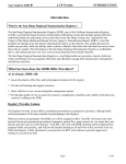
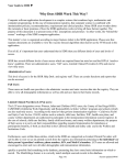
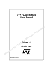
[Check to see whether all the components included in the following
diagram are included.]
Product guide
1) Main body
2) SD Card (Including User Manual and Software)
3) SD Card Reader
4) External Switch
5) Cable Mount
Main body
SD Card
External Switch Cable Mount
SD Card Reader
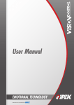
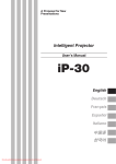
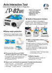
3. Names of each part
Main body is comprised of the module that processes and assesses status
on the camera, current image and situation with the internal CPU.
>>Name of main body’s each part is shown on the following diagram.
Product guide
&DPHUDOHQV
>)URQW@
+HDG)L[LQJ%XWWRQ
6'&DUGLQVHUWLRQSDUW
)1%87721
5(&%87721
0,&
>5HDU@
4. VEDR function
NOTICE : The VEDR mode is disabled during Continuous Recording mode. To enter the VEDR mode
[Event Recording]
When impact is felt by the vehicle, this device detects the shock
automatically, and records the image on a real time basis before 15sec.
/after 15 sec. an accident. At the same time, the device records
information related to time and vehicle’s 3-axis acceleration data, GPS
location information and speed information etc.
Impact results in case of vehicle accident, sudden braking, sudden curve,
irregular road surface, and impact to the main body and it is possible to
adjust impact level. When the impact level is low, recording takes place
frequently as the device detects even the minor braking. Storing does
not take place often when the impact level is high, but this in turn may
not record minor collision.
Saved accident data are stored into the internal Flash Memory and
downloaded to SD Card for about 10 seconds. After data download,
accident images are preserved within the internal Flash Memory as it is.
If SD Card is not inserted and data are stored in the internal Memory, you
can insert SD Card and press FN button for 3 seconds to all of contents of
Flash Memory to SD Card.
[Manual recording function]
This is the function that records image regardless of impact level. Press
on the REC button located at the back of the main body to record image
of setup before / after time, acceleration, and GPS location speed
information. Using this function when image is not recorded due to
minor collision enables you to record the data.
Product guide
user must press the FN button once. VEDR mode starts. By pressing FN button again the VEDR mode
stops and the Continuous Recording mode re-starts . If no SD-card is installed , the Roadscan enters
automatically the VEDR mode, Continuous Recording mode is disabled.
Product guide
[Stable image storing function using back-up power]
In the case of large accident, there is a potential that power will be
severed. However, accident image is saved safely even when power is
severed thanks to the built-in back-up power located in the main body.
At this time, however, image is recorded up to the point when power is
severed for safe image of accident storing, and does not record data
afterwards. Moreover, frames per second of the image may be lower
than the normal frames per second.
[Recording function that uses built-in Flash Memory]
It stores data that occurs due to impact and GPS data to be used for DT
using internal Flash Memory regardless to SD Card.
This product stores images and data up to 60 times for 15 seconds
before and after an accident (total 30 seconds) to allow check image
data using Manager Program mounted on SD Card. (If any accident
occurs after 60 times of accident images are stored, the oldest data is
deleted and new image is stored in the place.)
[Correct Use of SD Card]
If you insert or pull out SD Card during operation of
Card than the one provided when purchasing the product, be sure to
use recommended SD Card for normal operation.
[Capacity of SD Card]
Minimum available SD Card is 2G SD Card, of which 1G byte is used for
copying internal Flash Memory only.
[Image and Vehicle Data Analysis Function]
It is possible to analyze image and data at that time using provided
VEDR software.
[VEDR Impact Level]
It is possible to set up impact level at which the product recognizes that
it is an Event.
Value that is applied to the vehicle.
Normal Impact
Critical Impact
Recording
Pattern
Recording upon
Recording upon
large impact
and radical driving
Impact
Level Setup
Range
0.1G ~ 1.9G
1G ~ 2G
Initial
Impact Level
0.7G
1.1 G
Overwritten
Not overwritten
Remarks
Recording upon
REC button and
External Switch
When user presses
REC button or External
Switch upon necessity
To manage as same as
Normal Impact
5. Continuous Recording Function
When the product is powered on, it starts Continuous Recording
automatically after 20 seconds, and when FN button is pressed, it stops
Continuous Recording function.
It may use up to 16G SD Card that saves images for 12 hours with high
resolution or 25 hours with medium resolution. (See software guideline.)
Card.
Product guide
Type
Product guide
6. DT Function
DT function is to store route, time and speed during driving of the
vehicle.
DT data can be downloaded to SD Card by pressing FN button for
3seconds.
[Recording Time]
Total recording time of DT is about 30 days when driving for 24 hours a
day. Afterward, the oldest data is deleted.
[Speed, Location, Time Recording]
This product stores speed, location and time every 10 seconds when it
is connected to GPS.
[Speed]
It shows speed as a graph via speed window so as to allow more
accurate analysis of driving record. In addition, it displays speed on the
car speed meter panel to allow easy analysis.
[Location]
It shows latitude and longitude as numbers equivalently, but graph
display depends on use of Google Map.
When driving route display is enabled: It connects to Google Map to
display the current location on Google Map, and when DT data is
played, it displays changing location over time. At that moment, Google
Map can be expanded or reduced.
When driving route display is not enabled: It displays the entire route as
a line.
[REC button]
It is possible to record image manually by using REC (Record) button.
Press on the REC button to record image manually, and image and
information is recorded in Flash Memory and move to SD Card
automatically.
! Caution
event may not result in the case of minor contact accident or in the
case of contact accident involving vehicles that are moving at the same
speed. In this case, press on the REC button to record before and after
image for the time designated for recording.
[FN Button]
Continuous Recording is automatically started 20 seconds after the
product is powered on. When you press FN button, Continuous
Recording is stopped, and pressing it again, Continuous Recording is
started again.
To transmit event data and DT data stored in the internal
Flash Memory to SD Card you must press the FN button for 3 seconds.
FN BUTTON
REC BUTTON
Product guide
7. Button’s function
8. Guide on LED Display and Buzzer Sound
[Description of LED Display]
LED
Status
Status
Blink
Abnormal state on the device.
On
Operating status with power or battery.
Product guide
Status with no SD Card or unrecognized SD Card.
Blink
Storing images or upgrading device.
On
SD Card is normally operated.
GPS communication is not active.
Blink
On
GPS communication is available but location is
[Buzzer Sounds and LED Display upon Operation of Product]
6[RG
)WKFG6KOG
$W\\GT5QWPF
6WDUW
$IWHUERRWLQJ %HHS%HHS
%HHS
6KRUW
.'&+PFKECVQT
4GOCTMU
32:(56'&$5' 1RUPDO
DQG*36DUHWXUQHG VWDWXV
RQDQGRIILQRUGHU
,QFKDUJLQJ
(YHQW
5HFRUGLQJ
6WDUWVWRUDJH
%HHS%HHS
,QVWRULQJ
6WDUW
%HHSa/RQJ 6'&$5'WXUQHGRQ
/('
EOLQNV
VORZO\
/('
EOLQNV
IDVW
$IWHU
SUHVVLQJ
5(&
6'&$5'EOLQNV
EXWWRQ
%HHSa/RQJ 6'&$5'WXUQHGRQ VWRUDJH
VWDUWV
%HHS6KRUW
,QGRZQORDG
LQJ
'RZQ
&RPSOHWHG
6'&$5'EOLQNV
6'&$5'EOLQNV
$IWHUSUHVVLQJ %HHS%HHS
EXWWRQ
&RPSOHWHG
(Functions by
pressing the
FN button for
3 seconds)
6'&$5'EOLQNV
%HHS6KRUW 6'&$5'WXUQHGRQ
,QVWRULQJ
'RZQORDG
)ODVK
0HPRU\!
6'&DUG
6'&$5'EOLQNV
&RPSOHWHG
&RPSOHWHG
5(&%XWWRQ
([WHUQDO
6ZLWFK
%HHS6KRUW
6'&$5'EOLQNV
6'&$5'EOLQNV
6'&$5'EOLQNV
%HHS%HHS
6'&$5'WXUQHGRQ
Product guide
&RQWLQXRXV 6WDUWVWRUDJH
5HFRUGLQJ
,QVWRULQJ
9. Product Upgrade
This product may be subject to change of software in the future for
the purpose of performance improvement, etc.
Upgrade can be supported through websites of manufacturer and seller
and upgrade and installation should be executed by the user personally
in principle.
If you want to receive update through visit, please use the customers
center of the manufacturer or seller.
Product guide
ೢ How to upgrade the product
1) Connect SD Card to PC.
3) Insert SD Card to the product and power it on, upgrade is automatically
progressed.
10. Google Map Use
Google Map use is provided with charge up to 100 counts. If you want
to use it afterwards, connect www.iplk.com to pay charge.
The URL above may be changed upon situation of the company.
Software guide
1. Software Installation
(5) When a screen is displayed as below, press “Next” button.
Software guide
(1) Connect provided SD Card to PC.
(2) Open program folder within SD Card.
(3) Run setup.exe within program folder.
(4) When a screen is displayed as below, press “Next” button.
Software guide
(6) When a screen is displayed as below, press “Next” button.
(7) When a screen is displayed as below, press “Next” button.
(9) When program installation is completed, a screen is displayed as
below. Press “Finish” button to end installation.
Software guide
(8) When a screen is displayed as below, press “Install” button.
2 . Login
In order to use Google Map, it is required to enter provided ID and Password.
Use 6 character ID code, not email address
Use 6 character PW code.
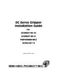
3. Description of Software Screen
Software guide
3
2
6
5
4
1
7
(1) Menu Button
˧It includes functions such as File View, Download, Device Setup, etc.
(2) Display Window
˧ It displays images of Event data or DT data.
(3) Google Map
˧It shows location information of data via Google Map.
(4) File List Window
˧
(5) Graph Display window
˧It displays acceleration data, impact data and speed data in sequence.
(6) Driving Information Display Window
˧It displays time information, location information, acceleration information,
driver information, etc. of data.
(7) Progress Bar
˧It displays progressing rate when executing download or other functions.
4. Function and Description of Button
(1) Mode Change
: It allows displaying VEDR data and DT data alternately.
When you press the button, display mode changes to VEDR display
mode and DT display mode alternatively. At the moment, shape of
button is also changed.
Button for VEDR Display Mode ඖ
Button for DT Mode ඖ
The following screen appears when the Search Button is clicked on.
Sets up the search folder.
Screen where user can select
folder is indicated when the
button is pressed on.
Search condition for recorded
date.
Search condition for user setup
values.
Software guide
(2) Search Open
Notice !!
When OK button is pressed while only folder is designated as shown on
Software guide
the database screen on the right. (Possible to search up to 10,000)
1) To search by date, designate the start and ending date on the date
dialog box, and check on the box on the left side and then press on
the OK button. Check on one box to search with one date alone.
(In the DT Mode, search is conducted with the day when driving
started as a standard.)
2) To search by impact value, input minimum and maximum values,
and then check the box on the left, pressing the OK button afterwards.
Input one value to search with only one impact value.
(Use only on the VEDR Mode, while it is meaningless in the DT Mode)
3) To search by impact speed value, input minimum and maximum
values. Then, check the box on the left, and press on the OK button.
Input one value if you wish to search with only one impact speed
value.
(Use only on the VEDR Mode, while it is meaningless in the DT Mode)
4) Car number, driver name and management number can select saved
value with User setup. Press on the OK button after checking the box
on the left.
5) All conditions can be searched with AND conditions.
(3) SD Card Open
Software guide
: It lists all of images within SD Card.
(4) File Open
(maximum of 10,000)
Software guide
(5) Download
: This is the function that downloads main body’s SD Card’s data to a PC.
Use Card reader to download main body’s data to a PC. To download,
press on the download button while SD Card is connected to a PC, and
the following Dialog box appears.
Check on the check box on the left side of the data that you want to
download among the saved data.
Press on the OK button on the dialog box after checking.
(6) Print
: prints the current screen as is.
It stores settings of the device into SD Card.
It allows setting up Impact Level, resolution, audio storage, etc.
[Impact Level]
If the product receives impact value larger than the impact level setting,
it stores data automatically.
If you want to record the image data less frequently, select higher value
of G.
It is possible to setup impact level by each X, Y, Z axes. Impact level is
saved when the OK button is clicked on after moving the bar to the
desired number.
X-axis => vehicle’s front and rear direction
Y-axis => vehicle’s left and right direction
Z-axis => vehicle’s upper and lower direction
[Voice Recording]
check box.
Software guide
(7) Device Setup
Software guide
(8) User Setup
Environment Settings that enable Management Settings and
environment setup that makes it possible to manage with vehicle
number, driver’s name and management number when it comes to
each serial number.
After vehicle number is registered, it is downloaded to the vehicle
number folder when it comes to the setup serial number, and it is
downloaded to the serial number folder when it comes to the serial
number that is not setup.
[Management Settings]
*How to input Management Settings
(1) Click on the Add button after inputting Serial No., Car No., Driver
Name and Management No.
At this time, at least one value among serial number, vehicle
number, driver’s name and management number must be input.
*How to delete setup Management Settings
(1) Click on the serial number to delete setup value on the list.
(2) Click on the Delete button.
(3) Click on the Save button after verifying deletion from the list.
[Environment Settings]
-Speed setup
KPH is selected when the unit of vehicle’s speed is km/h, and MPH in the
case of mile/h.
-Google Map ON/OFF
Select OFF when Google Map is not used.
Map usage Count does not increase from the subsequent execution
when FF is selected.
-Reload last work at startup
Check “Reload last work at startup” and press on the saving button.
prior to ending is indicated on the File List.
-Overspeed Setup
It is standard speed to be used to calculate Overspeed on DT mode.
Software guide
onto the list.
(9) Graph Display
Software guide
Displays the acceleration data and the impact data, speed data in detail.
Graph indication can be converted to Acceleration, Impact and Velocity
sequentially.
Click
button => The button will be changed to
and displays
the impact data.
Click
button => The button will be changed to
and displays
the speed data.
Click
button => The button will be changed to
and displays
the acceleration data.
(10) About Software
Shows the version of software and your registered serial number.
(11) Play Buttons
Play the video display continuously.
Pause the video display and initialize the video display.
Pause the video display.
Show next frame.
(12) Auxiliary Buttons
Graph indication conversion button
This is the function that can convert Graph indication, and it is possible
to convert Acceleration, Impact and Speed in sequence.
: Acceleration data indication
: Impact data indication
: Speed indication
Drive Route Drawing Button
It displays route on Google Map, that can operate on DT mode only.
It displays driving points (up to 1000 points) with driving record storage
interval value to set up location information of the driving data.
Drive Route Delete Button
This is the function that deletes path when path is indicated on the map.
Software guide
Show previous frame.
Driving Record Playing Speed Setup
DT playing speed setup
This is the function that sets up the speed to increase/decrease speed of
play on the DT mode.
Increases speed up to 4 compact disk access time to x 1 ˧ x 2 ˧ x 3 ˧
x 4 when
is pressed on
Software guide
Decreases speed up to 4 compact disk access time to x 1 ˧ x 1/2 ˧
x 1/3 ˧ x 1/4 when
is pressed on.
This function operates only when play button is pressed on.
5. Description of Data Information Display
To display recording time of the current image frame
display mode)
To display latitude out of location information for the current
image frame
registered with user setup)
with user setup)
registered with user setup)
under DT mode)
Software guide
To display longitude out of location information for the current
image frame
6. How to download and play data
1) Connect SD Card having device data to PC.
2) After executing software, click Download button.
4) When download is completed, click File Open button.
6) Click Play button.
7) It is possible to display downloaded data as shown on a window
Software guide
below.
8) In order to display DT data, click “Mode Change” button.
9) As the button changes to ,
it is switched over to DT display
window.
10) Click File Open button.
12) Click Play button.
13) It is possible to display downloaded DT data as shown on a window
below.
Software guide
In order to display travel route, click “Travel Route Drawing” button.
7. Acceleration data interpretation method
The following includes various data interpretation examples.
analyze the type of accident.
Time
Software guide
[Stop State]
Time
[Acceleration]
Time
[Brake State]
Time
[Right Turn State]
Time
[Left Turn State]
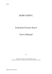
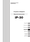
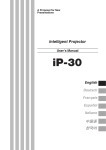
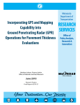
8. Impact assessment graph
If the IMPACT value of one record is greater than the trigger G
value, then the system is triggered, and an image-and-data set
is recorded into memory.
0 .5 G
Trigger G Value
[sensitivity of
trigger condition]
Time
[IMPACT data graph]
9. Description of DT Mode Window
on the top left corner of the window. Driving Distance indicates daily
driving distance, and Driving Time displays actual driving time / travelling time.
In addition, Overspeed Time indicates driving time at higher speed than
standard speed set by user setup .
Software guide
IMPACT
1. Caution during installation
Installation guide
Installation guide
Prior to installation, check whether contents of the product are included,
and mount according to the set procedure after understanding the contents
of the installation guide.
1) During product installation, even when the lever of transmission is set for
the N level, it is necessary to mount on the ground surface on a perpendicular
2) Select location for mounting that does not block driver’s view at the mirror
located in front of the vehicle.
3) When main body is mounted, check whether location is one that does not
limit the room mirror’s movement, and select a location that is not intervened
even when room mirror is maneuvered.
4) Clean the mirror at the location where adhesion will take place by using dry
cloth prior to attaching onto vehicle.
5) When installing vehicle, install so that other safety devices in the vehicle are
6) When vehicle’s power is input, check whether LED and buzzer sound come
7) The above mentioned product records the image data input from the
camera.
2. Mounting
When vehicle is moving or stopped or when contact accident or collision
results, this product records the before and after of the accident into
image. At the same time, this product records vehicle’s acceleration
Basic mounting location of the product is top or bottom of front
window of the vehicle. Attach the product on the position where safe
driving is not obstructed.
1
2) Bottom Mount: In case a navigation device is mounted at the center of the
vehicle, it allows better image at night.
Install at a location devoid of intervention when maneuvering room mirror.
Mount at a distance so that it does not fall into the range of room mirror
operation since intervention may result when room mirror is maneuvered by
driver or passenger.
Installation guide
2
3. Mounting sequence
Product’s basic mounting location is located at the upper part of the
center of the vehicle’s front mirror. This location is the front part of the
room mirror in the case of the passenger car. Attach the part with the
tape attached onto the mirror, and adjust the angle so that it becomes
perpendicular to the ground surface to complete the mounting.
Installation guide
Step 1) Take out the cover of the two-sided tape attached on the main
body.
Step 2) Place the main body at the vehicle’s center.
Step 3) Press button front/rear angle so that the main body mounted on
the front glass to be right angle.
Step 4) When adjustment is completed, release the button to check if it is
Step 5) Connect power with power cable.
Step 6) Connect External Switch. It is possible to use External Switch to save
Event Data on emergency. Attach External Switch on the desired
location.
Step 7) When Beep Beep Beep (short sound) sounds after connecting
power, POWER, SD-CARD and GPS LEDs turn on for 20 seconds and
SD Card LED blinks, mounting is normally completed. GPS LED may
blinks for the time being according to ambient situation.
Please be care about Room Mirror.
Installation guide
Notice!!
User can connect “ Secret emergency button” with Roadscan Pro by
cabling as below.
4. Wiring Guide
Installation guide
This product supplies power by connecting to the vehicle with power cable.
To arrange power cable, it is possible to use the mount that is provided to
arrange the power cable.
How to use the mount
1. Eliminate the sticker located at the rear of the mount, and
attach onto desired location.
2. Fit in the power cable onto the attached mount
Before suspecting malfunction
1) When image cannot be recorded,
1-1) Check whether there is SD Card in the main body.
1-2) Check whether it is SD Card provided by our company. Ordinary SD Card
may not record.
1-3) recording may have failed due to the failed impact detection depending on
the acceleration impact level.
(! Caution) In this case, image is recorded using the moment when the
manual recording button was pressed on as the standard.
2) Recorded image may not display everything depending on the distance with
the number plate of the vehicle in front, lighting, and vehicle’s speed.
3) Placing bright object or object that emit light in front of the vehicle’s front
especially at night.
4) GPS signal may not be received due to the blocking of the signal at
underground parking lot, tunnel and skyscrapers, and valleys and large trees.
5) In case audio is not stored, please conform if audio storage button is checked
on the software program.
6) When the quality of image is not good
Check whether main body’s lens is contaminated, and clean with cloth for
eyeglasses.
7) When the image is faced excessively towards the sky or the ground.
Check whether main body is facing vehicle’s front part, and adjust
perpendicular to the ground surface.
8-1) Check whether main body’s power cable is connected properly.
8-2) Pull out SD Card from the main body and power on, or format SD Card and
power on again.
9) If you pull out SD Card in storage from carelessness, the product may have an
error but it can be used again by formatting SD Card.
10) If there is no image on the software, please contact the seller.
Product specs and operation environment
Normal operation voltage
12V, 24V
Minimum operation voltage
9V
Maximum operation voltage
32V
Maximum power consumption amount
3W
Operating temperature
-20 degrees ~70 degrees
Preserving temperature
-40 degrees ~85 degrees
Camera Type
Color CMOS Camera
Maximum Camera Pixel
350K
Actual Camera Pixel
320K
Average number of images recorded
24 Frame / second
Lowest intensity of illumination for operation
Lens angle
Image recording resolution
1 lux
120 degrees
640 x 480
GPS
Installed in Main Body
Size
91x88x40 mm
Weight
Minimum operation PC environment for Roadscan Pro Manager:
OS : Windows XP, Vista
RAM : 256 MB RAM
HardDisk capacity : 32MB
At least CPU Pentium4 1.5GHz recommended
120 g
Warranty policy
ඞ Warranty regulation
was used normally within the warranty period (for one year from the day of
purchase).
where you purchased the product.
3. The following cases require you to pay for repair even during warranty period.
(a) When malfunction is caused by user’s mistake.
(b) Malfunction and damage caused during transport, movement and fall after
product is purchased
abnormal voltage, and use of power besides the designated (voltage
*frequency) and other natural calamities
purchased the product.
- Regarding warranty and A/S
Warranty period is for one year from the day of purchase.
the store and check whether day of purchase and storeଵ are included.
Read it carefully and keep it well.
When requesting repair, check wiring state and whether there is malfunction
caused by maneuvering method. Continue to repair when there is a problem.
where you purchased the product. We will repair based on the contents of the
- When warranty period has expired: Consult with the store where you
purchased the product. When product function is maintained due to repair, we
can repair for a charge according to the customer’s desire.
Importeur / Distributeur BENELUX
RCBI BV
Spoorstraat 7 - U705
4702VV Roosendaal
Nederland
GSM NL : 06-32031740
GSM B : 0495-518486
Tel/Fax NL : 0164-602928
Email : [email protected]
www.roadscan.nl
www.roadscan.be