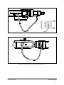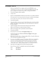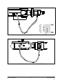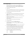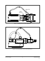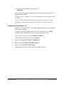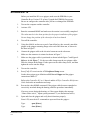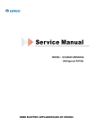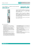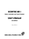
1
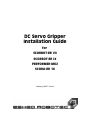
&%"5GTXQ")TKRRGT
+PUVCNNCVKQP")WKFG
HQT"
5%14$16/'4"8++
5%14$16/'4"+:
2'4(14/'4//-4
5%14#/'4"36
%CVCNQI"%322299"/"4GX0$
Copyright ©1999 Eshed Robotec (1982) Limited
Catalog #100077 Rev.B
March 1999
Every effort has been made to make this book as complete and accurate as
possible. However, no warranty of suitability, purpose, or fitness is made or
implied. Eshed Robotec is not liable or responsible to any person or entity for loss
or damage in connection with or stemming from the use of the software, hardware
and/or the information contained in this publication.
Eshed Robotec bears no responsibility for errors which may appear in this
publication and retains the right to make changes to the software, hardware and
manual without prior notice.
Table of Contents
SCORBOT-ER VII
1
SCORBOT-ER IX
6
PERFORMER-MK2
10
SCORA-ER 14
14
SCORBOT-ER VII
Before you install the DC servo gripper, make sure your Controller-A contains
the piggy-back board with 68020 CPU and 68881 FPU (floating point unit).
If the controller does not have these components, uppgrade the EPROMs in
Controller-A to Version F.44 or later.
After you have exchanged the EPROMs, you must configure the controller.
1.
Turn on the computer and the controller.
2.
Activate ATS.
3.
Enter the command HOME and make sure the routine is successfully completed.
The robot must be in the home position for the proper installation of the gripper.
Do not change the position of the robot after it is homed.
4.
Turn off the controller.
5.
Using four M4x10 socket screws and a 3mm Allen key (hex wrench), attach the
gripper to the gripper mounting flange at the end of the robot arm, as shown in
the inset in Figure 1.
6.
Connect the gripper cable to the electrical connector on the robot arm.
Make sure the connector is oriented as shown in Figure 1.
7.
Make sure the gripper cable is positioned as shown in Figure 2.
8.
Turn on the controller.
Press [Shift]+F10 to activate the ATS Backup Manager.
9.
10.
Load the parameter file GRP7 from the ATS directory using the options:
“ Restore PARAMETERS” and “ RESTORE from disk (F5)” .
Execute the robot HOME command. If the gripper cable becomes entangled or
excessively stretched during the homing, abort the procedure immediately.
The gripper has a rotation of ±270°. Do not attempt to move the gripper beyond
this limit.
At the end of each work session (before turning off the controller), or before
homing the robot, make sure the gripper’s position is as shown in Figure 2.
Installation Guide
9903
-1-
DC Servo Gripper
Figure 1: Attaching Gripper to SCORBOT-ER VII
Figure 2: Connecting Gripper Cable to SCORBOT-ER VII
DC Servo Gripper
-2-
Installation Guide
9903
SCORBOT-ER IX
Before you install the DC servo gripper, make sure the EPROMs in your
Controller-B are Version 2.25 or later. Upgrade the EPROMs if necessary. Be
sure to configure the controller after you have exchanged the EPROMs.
1.
Turn on the computer and the controller.
2.
Activate ATS.
3.
Enter the command HOME and make sure the routine is successfully completed.
The robot must be in the home position for the proper installation of the gripper.
Do not change the position of the robot after it has been homed.
4.
Turn off the controller.
5.
Using four M4x10 socket screws and a 3mm Allen key (hex wrench), attach the
gripper to the gripper mounting flange at the end of the robot arm, as shown in
the inset in Figure 3.
6.
Connect the gripper cable to the electrical connector on the robot arm.
Make sure the connector is oriented as shown in Figure 3.
7.
Make sure the gripper cable is positioned as shown in Figure 4.
8.
Turn on the controller.
9.
Press [Ctrl]+F3 to activate the ATS Peripheral Setup screen.
Set the robot gripper type definition to DC Servo Gripper and the gripper
connection to Axis 6.
Refer to the Controller-B User’s Manual and the ATS for Controller-B Reference
Guide for details on installation and setup.
11.
Execute the robot HOME command. If the gripper cable becomes entangled or
excessively stretched during the homing, abort the procedure immediately.
If an error occurs during the homing, or if the system displays the message
“ Home failure axis 6,” adjust system parameter 75 (see instructions below).
12.
Open and close the gripper and verify that it functions properly.
From ATS, enter the ACL commands to open and close the gripper:
Type:
open [Enter]
Type:
close [Enter]
Installation Guide
9903
-3-
DC Servo Gripper
Figure 3: Attaching Gripper to SCORBOT-ER IX
Figure 4: Connecting Gripper Cable to SCORBOT-ER IX
DC Servo Gripper
-4-
Installation Guide
9903
Or from the teach pendant, key in a few times:
Open/Close
If you see that the gripper does completely close, adjust a system parameter 75
(see instructions below).
The gripper has a rotation of ±270°. Do not attempt to move the gripper beyond
this limit.
At the end of each work session (before turning off the controller), or before
homing the robot, make sure the gripper’s position is as shown in Figure 4.
Changing System Parameter 75
Parameter 75 defines the DAC value applied to the gripper motor when opening
and closing the gripper.
To improve gripper operation, increase the value of parameter 75 to -2500.
(Default value is -2000.) Do not enter a value which exceeds -2500.
1.
From ATS, enter the ACL command PRIV ON [Enter].
When prompted for the password, press [Enter].
2.
Enter the command LET PAR 75 -2500 [Enter]
3.
Enter the command INIT CONTROL [Enter].
4.
Enter the command PRIV OFF [Enter].
5.
Repeat the homing routine, and again check gripper operation.
Installation Guide
9903
-5-
DC Servo Gripper
Á
DC Servo Gripper
-6-
Installation Guide
9903
PERFORMER-MK2
Before you install the DC servo gripper, make sure the EPROMs in your
Controller-B are Version 2.25.01 or later. Upgrade the EPROMs if necessary.
Be sure to configure the controller after you have exchanged the EPROMs.
1.
Turn on the computer and the controller.
2.
Activate ATS.
3.
Enter the command HOME and make sure the routine is successfully completed.
The robot must be in the home position for the proper installation of the gripper.
Do not change the position of the robot after it has been homed.
4.
Turn off the controller.
5.
Using four M5x10 socket screws and a 4mm Allen key (hex wrench), attach the
gripper adapter plate to the flange at the end of the robot arm, as shown in
Figure 5.
6.
Using four M4x10 socket screws and a 3mm Allen key, attach the gripper to the
adapter plate, as shown in Figure 5.
7.
Gently connect the gripper cable to the D9 connector on the robot arm, as
indicated in Figure 6.
8.
Make sure the gripper cable is positioned as shown in Figure 6.
9.
Turn on the controller.
11.
Press [Ctrl]+F3 to activate the ATS Peripheral Setup screen.
Set the robot gripper type definition to DC Servo Gripper and the gripper
connection to Axis 6.
Refer to the Controller-B User’s Manual and the ATS for Controller-B Reference
Guide for details on installation and setup.
12.
Execute the robot HOME command. If the gripper cable becomes entangled or
excessively stretched during the homing, abort the procedure immediately.
If an error occurs during the homing, or if the system displays the message
“ Home failure axis 6,” adjust system parameter 75 (see instructions below).
13.
Open and close the gripper and verify that it functions properly.
From ATS, enter the ACL commands to open and close the gripper.:
Type:
open [Enter]
Type:
close [Enter]
Installation Guide
9903
-7-
DC Servo Gripper
Adapter Plate
Gripper
Mounting
Figure 5: Attaching Gripper to PERFORMER-MK2
Figure 6: Connecting Gripper Cable to PERFORMER-MK2
DC Servo Gripper
-8-
Installation Guide
9903
Or from the teach pendant, key in a few times:
Open/Close
If you see that the gripper does completely close, adjust a system parameter 75
(see instructions below).
The gripper has a rotation of ±270°. Do not attempt to move the gripper beyond
this limit.
At the end of each work session (before turning off the controller), or before
homing the robot, make sure the gripper’s position is as shown in Figure 6.
Changing System Parameter 75
Parameter 75 defines the DAC value applied to the gripper motor when opening
and closing the gripper.
To improve gripper operation, increase the value of parameter 75 to -2500.
(Default value is -2000.) Do not enter a value which exceeds -2500.
1.
From ATS, enter the ACL command PRIV ON [Enter].
When prompted for the password, press [Enter].
2.
Enter the command LET PAR 75 -2500 [Enter]
3.
Enter the command INIT CONTROL [Enter].
4.
Enter the command PRIV OFF [Enter].
5.
Repeat the homing routine, and again check gripper operation.
Installation Guide
9903
-9-
DC Servo Gripper
Á
DC Servo Gripper
-10-
Installation Guide
9903
SCORA-ER 14
Before you install the DC servo gripper, make sure the EPROMs in your
Controller-B are Version 2.25 or later. Upgrade the EPROMs if necessary.
Be sure to configure the controller after you have exchanged the EPROMs.
1.
Turn on the computer and the controller.
2.
Activate ATS.
3.
Enter the command HOME and make sure the routine is successfully completed.
The robot must be in the home position for the proper installation of the gripper.
Do not change the position of the robot after it has been homed.
4.
Turn off the controller.
5.
Using four M4x10 socket screws and a 3mm Allen key (hex wrench), attach the
gripper to the gripper mounting flange at the end of the robot arm, as shown in
the inset in Figure 7.
6.
Connect the gripper cable to the electrical connector on the robot arm.
Make sure the connector is oriented as shown in Figure 7.
7.
Make sure the gripper cable is positioned as shown in both Figure 7 and Figure 8.
Refer to A-A in Figure 7. Fit the two cable clamps onto the two gripper cables.
Place the clamps on the flange. Fit the spacer on the cable clamp screw, and then
tighten the screw onto the flange.
8.
Turn on the controller.
9.
Press [Ctrl]+F3 to activate the ATS Peripheral Setup screen.
Set the robot gripper type definition to DC Servo Gripper and the gripper
connection to Axis 5.
Refer to the Controller-B User’s Manual and the ATS for Controller-B Reference
Guide for details on installation and setup.
10.
Execute the robot HOME command. If the gripper cable becomes entangled or
excessively stretched during the homing, abort the procedure immediately.
If an error occurs during the homing, or if the system displays the message
“ Home failure axis 6,” adjust system parameter 75 (see instructions below).
11.
Open and close the gripper and verify that it functions properly.
From ATS, enter the ACL commands to open and close the gripper.:
Type:
open [Enter]
Type:
close [Enter]
Installation Guide
9903
-11-
DC Servo Gripper
Gripper
Mounting
Flange
Figure 7: Attaching Gripper to SCORA-ER 14
Figure 8: Connecting Gripper Cable to SCORA-ER 14
DC Servo Gripper
-12-
Installation Guide
9903
Or from the teach pendant, key in a few times:
Open/Close
If you see that the gripper does completely close, adjust a system parameter 75
(see instructions below).
The gripper has a rotation of ±270°. Do not attempt to move the gripper beyond
this limit.
At the end of each work session (before turning off the controller), or before
homing the robot, make sure the gripper’s position is as shown in Figure 8.
Changing System Parameter 75
Parameter 75 defines the DAC value applied to the gripper motor when opening
and closing the gripper.
To improve gripper operation, increase the value of parameter 75 to -2500.
(Default value is -2000.) Do not enter a value which exceeds -2500.
1.
From ATS, enter the ACL command PRIV ON [Enter].
When prompted for the password, press [Enter].
2.
Enter the command LET PAR 75 -2500 [Enter]
3.
Enter the command INIT CONTROL [Enter].
4.
Enter the command PRIV OFF [Enter].
5.
Repeat the homing routine, and again check gripper operation.
Installation Guide
9903
-13-
DC Servo Gripper