1
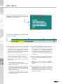
spa
Driving towards the future
Injection System
DREAM XXI N
Software and system set-up
user’s manual
by OMVL
Software manual DREAM XXI
INDEX
• Company OMVL spa presentation ....................................................... 4
• Quality................................................................................................... 5
• Introduction .......................................................................................... 7
• Main menu ........................................................................................... 8
• Vehicle configuration ........................................................................... 9
F1 Change-Over ......................................................................... 10
F2 Lambda ................................................................................. 12
F3 Emission ................................................................................ 13
F4 Sensors .................................................................................. 14
F5 Map ....................................................................................... 15
F6 Adjustments ........................................................................... 17
F7 Modify carb. ........................................................................... 17
• Display ............................................................................................... 19
• Autocalibration .................................................................................. 20
• Save Configuration ............................................................................ 21
• Load Configuration ............................................................................ 21
• ECO Reprogramming ........................................................................ 22
3
Presentation
COMPANY OMVL spa
STATE OF ART
The Italian company OMVL is a leading player
in the Alternative Fuel Vehicles (AFV) sector,
designing, manufacturing and marketing
complete fueling systems for gas-propelled
vehicles and for the conversion of engines
from petrol to CNG and LPG.
The popularity of motor vehicle gas fueling
systems has been boosted mainly by 2
factors: fuel economy (the cost of CNG and
LPG globally is much lower than that of petrol,
and there is also the bonus of reduced engine
wear), and lower emission levels.
Established in 1980 at Argelato near Bologna,
since 2001 OMVL has been part of the SIT
Group, an Italian multinational specializing
in safety, monitoring and control systems
for domestic gas heating appliances and for
Alternative Fuel Vehicles. The merger has given
a further impulse to the internationalization
of OMVL, which currently collaborates with
the most important manufacturers of motor
vehicles worldwide, including Volkswagen,
Citroën, Ford and FIAT, selling to Europe
(43%), the Americas (14%) and Australasia
(43%).
All around the world, in point of fact, there
is an increasing willingness to develop and
encourage new technologies to exploit
clean energy sources. Where environmental
awareness is particularly keen, as in the
countries of Northern Europe, and where levels
of pollution are especially high (India, Mexico),
local governments encourage the installation
of CNG and LPG systems by offering tax
breaks and subsidies.
The
company’s
headquarters
and
manufacturing premises are now based in
Pernumia (Padua), while commercial branches
or production plants are located in Iran, Brazil
and Argentina.
4
MISSION E VISION
OUR PRODUCTS
The adoption of gas as an alternative fuel for
motor vehicles - and other applications too
- can certainly be considered the stepping
stone to a future characterized by the use of
cleaner energy with a lower carbon content,
since it is handy and economical, competitive
and relatively plentiful, besides being by far the
least pollutant of known fossil fuels. It would
also provide a promising source of hydrogen,
in the event that fuel cells should ultimately
replace conventional fueling systems in the
not too distant future.
All this is a matter of conviction for OMVL,
and forms the basis of the company’s mission
statement: optimum performance with minimal
emissions, a combination giving Customers
maximum satisfaction and reliability, and a
steadily cleaner future.
OMVL products - all marketed under the
REG® brand - are the outcome of longterm research and advanced technology.
Thanks to a wealth of know-how accumulated
over a quarter-century of activity and
experience in the field, solid investments
and regular feedback from users on products
and their applications, OMVL is able to offer
business partners the most advanced and
workably competitive solutions supplied within
the most competitive time scales.
Reducers, mixers, ECUs, accessories and
parts are designed and produced by OMVL,
with pressure diecasting, machining, assembly
and testing operations all organized entirely as
internal procedures.
spa
Quality
QUALITY
OMVL is a Company certified with a Quality
System ISO 9001:2000.
This certificate, released by TUV Italy which belongs to the German Group TUV
Suddeutschland - is related to the entire
process of designing, manufacturing and
marketing of gas components and complete
fuel supplying systems for gas-propelled
vehicles.
OMVL Company processes are defined,
monitored and subjected to programs of
constant improvements in order to reach
high goals in efficency and effectiveness
which guarantee a continuous and increasing
consumer satisfaction of our products
branded REG®.
REG® products are subjected to a process
control for the entire manufacturing course
which starts from in-coming material control
to final tests under pressure performed on
the production as a whole in accordance with
the international and internal Regulations in
order to guarantee and maintain continually a
high standard of quality and safety.
The LPG and CNG converting components
are approved in line with the European
Regulations R67 01 and R110. Moreover, the
CNG converting components are approved
in accordance with ISO 15500 Regulation.
REG® converting systems for small, medium
and high power engines are approved in line
with the European standards for emissions of
pollution Euro4.
5
6
spa
Introduction
MINIMUM COMPUTER REQUIREMENTS FOR SOFTWARE INSTALLATION
• Operating system: ............ Windows 98 SE or later
• Memory (ram): ................... 16 Mbytes at least
• Hard disk: .......................... 20 Mbytes of free space at least
• Screen resolution:............. 800 x 600 or better
Internet Explorer version 5.5 or later should also be installed
INSTALLING THE SOFTWARE
When you are ready to install the software, insert the cd-rom in the computer and wait for the
installation wizard to pop-up.
Should the wizard fail to start, click the “Start” button in the “Applications Bar” and select
“Run...”. Enter: “D:\setup.exe” (where D is your Cd-rom drive).
You will be asked to choose a directory where the software will be installed; we recommend to
choose the default one.
Once the installation has been completed, the icon of the program will be automatically put on
your desktop.
INTRODUCTION
It’s not necessary to connect the ECU to start the software. However, if you want to program the
ECU, you need to connect the it to the PC with an interface cable, part number OMVL 411028
(not supplied in the kit, should be ordered separately).
Furthermore, the control unit must be powered by the +12 V battery voltage (via the red-black
wire) and properly grounded (black wire).
7
Main Menu
This menu is used to access all the submenus
contained in the software, all of which are
listed and described below:
The following information is provided at the
bottom of the page:
(1)
(2)
(3)
1) This indicates if the control unit is connected
2) This is the name that can be given or has been
or not connected to the PC. It is important to
remember that any settings made when the
control unit is not connected will be lost at
the time of connection, unless they have been
already saved in a configuration file.
given to the configuration of the vehicle; for a
new control unit, the standard configuration
is “standard LPG”. The control unit must be
connected to the configuration software in order
to download an existing configuration into the
control unit.
The program will automatically attempt to
connect to the control unit when you open it.
If the program can’t connect to the ECU, a
window will pop-up reporting an error. You
should check:
(4)
3) This is the version of the control unit’s software;
select the “ECU REPROGRAMMING” sub-menu
to update it.
Note: this is only possible if INTERNET
- the connection of the serial interface,
- the connection of the control unit to the
battery and to ground,
- if the key has been switched off for more than an
hour, you should switch it on for a few seconds
or crank-up the car, if the switch doesn’t light
up with the instruments.
To attempt a connection again, open the
“Connection” menu at the top of the window
and select “Connect”.
8
EXPLORER version 5.5 or later is installed on
your PC.
4) This indicates if the current configuration
downloaded into the control unit uses the
operating parameters for CNG or LPG; go to
the “VEHICLE CONFIGURATION” sub-menu to
select the type of fuel.
spa
Vehicle configuration
This sub-menu is made up of 7 pages (when
the REG009 dongle-key is plugged into the
PC) where you can change the parameters
that define the behaviour of the gas control
unit. These parameters must be set according
to the signals that are present on the vehicle.
At the bottom of any page you have a resuming
sight of the gas ECU parameters.
(1)
(2)
(3)
1) This box displays whether the vehicle is powered
by petrol or gas. The description CUT-OFF may
also appear when the system is in cut-off.
2) This box displays the:
Engine Revs currently read by the control unit.
T.gas is the temperature of the gas inside the
injection rail.
T.reducer is the temperature of the water inside
the pressure reducer.
(4)
(5)
Press.gas the difference in pressure between
the injection rail and the manifold air pressure
of the intake, read by the pressure sensor
supplied in the kit
MAP Manifold Air Pressure reading (only if
you are using an AEB025 sensor) and type of
sensor used.
5) This box displays the voltage of the lambda
probe and the gas level in the tank (in a 0 to
255 range).
3) This box displays the gas (Tinj.gas) and petrol
(Tinj.petrol) injection times.
4) In this box you can see:
Info: if you do not connect the purple wire to the
lambda probe, you can’t read the lambda voltage
on the screen.
9
F1 Change - over
(1) Note: all the parameters painted in
YELLOW
can be changed only when the key is
off and the change-over switch is off.
FUEL TYPE
This box is used to reset the control unit to the
default parameters for the selected fuel type.
Select:
- GPL for vehicles powered by LPG;
- METHANE for vehicles powered by CNG.
The selecion of LPG or METHANE changes
also the directory where the configuration
files are saved (see Load configuration
paragraph).
INJ.
ISelect the type of petrol injection of the
original ECU:
• Sequential: the petrol injection is
sequential
• Full-group: the petrol injection is halfgroup or full-group.
INJECTORS
Choose the type of gas injectors installed:
OMVL Standard or OMVL Fast
REDUCER
This parameter is only available in
configuration, because there are 3
reducers:
- STD: : Standard (0.9 bar) for 4
engines up to 110KW of power
- MP: Medium Power (1.2 bar) for
cylinders engines up to 150KW
10
the LPG
types of
cylinders
4-5 or 6
- HP: High Power (1.7 bar) for 6-8 cylinders
engines up to 220KW
TYPE OF REVOLUTION SIGNAL
This sets up the control unit to read the
engine’s revs with the BROWN wire:
- STANDARD, select this when the BROWN
wire i connected to:
- crank or cam shaft position sensor giving a 0
÷ 12 V, square-wave output;
- negative post of the coil pack.;
WEAK SIGNAL: select this when the BROWN2
wire is connected to:
- crank or cam shaft position sensor giving a 0
÷ 5 V, square-wave output;
- static ignition control giving 0 ÷ 5 V squarewave output.
Note: if you are not sure of the signal you get
on the BROWN wire, you should check it using
an oscilloscope.
NO. OF CYLINDERS
This parameter is used to set how many
cylinders the vehicle has and therefore how
may gas injectors the ECU should control: set
3 CYLINDERS or 4 CYLINDERS according to
the number of the vehicle’s cylinders.
Should you use a control unit for 5-6-8 cylinders,
the following options will also be displayed in
the selection box: select 5 CYLINDERS, 6
CYLINDERS or 8 CYLINDERS according to
the number of the vehicle’s cylinders.
spa
F1 Change - over
IGNITION TYPE
This parameter is used by the control unit
to compute the engine speed accurately,
depending on the type of signal the BROWN2
wire reads.
- ONE COIL: for vehicles with one coil per
spark-plug and the BROWN2 wire connected
to the negative of a coil;
- TWO COILS: for vehicles with one coil each
two spark-plugs and the BROWN2 wire
connected to the negative of a coil;
- RPM SENSOR: for vehicles with one coil
and mechanical distributor (BROWN2 wire
connected to the negative of the coil) and
for vehicles where the BROWN2 wire is
connected to a shaft position sensor.
- RPM SENSOR2: for all 8 cylinders vehicles
that give a double RPM reading with the
RPM SENSOR selected.
NOTE2 : the BROWN wire is in the gas control
unit harness
REVS. THRESHOLD FOR CHANGE-OVER
This sets the number of revs required for
changeover to gas. Set the number of revs
that you want to reach before the petrol to gas
changeover takes place.
GAS even if the temperature falls below the
threshold temperature while running on gas.
We recommend setting a temperature
between 20°C and 45°C: if you set a too low
temperature, the Petrol to Gas changeover
will take place when the reducer is not warm
enough to ensure a sufficent gas supply; if the
temperature you set is too high, it will take a
long time to switch to gas.
CHANGE OVER FROM PETROL-GAS
DELAY
Set the minimum time the ECU waits from the
engine start before switching to gas (even if
the reducer’s temperature has already reached
the threshold temperature). This delay lets the
original ECU perform all the checks it needs on
the vehicle’s sub-systems, whitout annoying it
with the gas power.
Reset ecu
parameters
and
go
to
base
If you press this button, all the parameters
in the control unit are cleared and the
configuration is reset to the default one. We
recommend to use this button ONLY in the
following circumstances:
FOR
- after
each
use
of
the
“ECU
REPROGRAMMING” feature to update the
ECU to a new firmware: we recommend
you press this button before any other
modification on the configuration;
This sets the temperature of the pressure
reducer required for the changeover to gas:
the control unit WILL SWITCH TO GAS under
this temperature.
The control unit will continue to operate on
- if you are not sure that all the parameters
have been set correctly and you want to
start from scratch again: press this button
to restore the default configuration and
clear all parameters.
REDUCER TEMPERATURE
CHANGE-OVER
11
PAGE F2 LAMBDA
TYPE OF LAMDA PROBE
the control unit car clearly read the lambda
probe voltage only if you set this parameter
correctly. Please check that the lambda probe
is working with a digital multimeter, before you
select the type of Lambda Probe.
WARNING:
Connect only the PURPLE wire to the lambda probe: the GREY wire MUST REMAIN DISCONNECTED!
If you do not connect the PURPLE wire, it is not necessary to set the “TYPE OF LAMBDA PROBE”
The GREY wire should be connected only for the emulation.
0÷1V
0÷5V
Select this option if the voltage output of
the lambda probe is:
approximately 0 ÷ 0.2 V for lean mixture;
approximately 0.8 ÷ 1 V for rich mixture.
Select this option if the voltage output of
the lambda probe is:
approximately 0 ÷ 0.2 V for lean mixture;
approximately 4.8 ÷ 5 V for rich mixture.
5 ÷ 0 V Select this option if the voltage
output of the lambda probe is:
approximately 4.8 ÷ 5 V for lean
mixture;
approximately 0 ÷ 0.2 V for rich
mixture.
NUMBER OF FRONTAL LAMBDA
PROBES
Set the number of pre-cat lambda probes
installed in the vehicle: 1 or 2
FUEL TRIM BANK 2
If you set 2 frontal lambda probes, you can
increase or decrease this correction value
(form –20 to +20) for the second bank, in case
of 6-8 cylinders engine.
This correction is applied to the K ratio defined
in the map of the first bank. If the correction is
set to 0, both banks use the same K ratio.
0,8 ÷ 1,6 V Select this option if the voltage
output of the lambda probe is:
approximately 0.7 ÷ 0.8 V for lean
mixture;
approximately 1.4 ÷ 1.6 V for rich
mixture.
UEGO
12
Select this option only for wide-band
resistive probes with 5 wires.
spa
PAGE F3 EMISSIONS
The parameters on this page
are used only for emission
tests. They become effective
only if you cut the wire of the
lambda probe (black wire, in
a 4 wires probe), connect the
piece coming from the probe
to the PURPLE wire of the gas
ECU and the piece going to
the original ECU to the GREY
wire of the gas harness.
Please take a look to the
connection scheme, if your
probe is a 5 wires UEGO
probe.
HIGH EMULATION LEVEL*
While idling the car in petrol, read the maximum
lambda probe’s voltage and set this parameter
accordingly.
Connection scheme for UEGO, 5-wires
lambda probes
Type BOSH
LOW EMULATION LEVEL*
While idling the car in petrol, read the minimum
lambda probe’s voltage and set this parameter
accordingly.
*: the default values are set accordingly to the
type of lambda probe you choosed in the
“F2 Lambda” page.
INITIAL EMULATION DELAY
Type NTK
When you start the engine, the gas ECU will
activate the emulation after the amount of time
you set. Set it to 0 to disable the emulation.
13
PAGE F4 SENSOR
TYPE OF MAP SENSOR
Lets you choose the type of MAP sensor
installed: AEB025 or AEB013.
TYPE OF GA LEVEL SENSOR
This sets the type of level sensor that you
use:
AEB -set this if you are using a sensor
with standard AEB output signal (like
the AEB1050); for connection instructions, look to the installation diagram
for the gas control unit.
0 - 90 ohm -set 0 - 90 ohm if the sensor gives an output from 0 to 90 ohm
(like the AEB1090); refer to the installation diagram for the gas control unit.
Non standard – select this option for
all non AEB sensors that give an output
directly proportional to the gas level in
the tank (0, 255).
With this option selected you can define the thresholds for the level gauge
in steps of 1⁄4 of the tank. The maximum value is for the full level, the minimum for the empty level.
Non standard inverted – select this
option for all non AEB sensors that give
an output inversely proportional to the
gas level in the tank (255, 0).
With this option selected you can define the thresholds for the level gauge
in steps of 1⁄4 of the tank. The maximum value is for the empty level, the
minimum for the full level.
14
spa
PAGE F5 MAP
It is possible to modify the gas mixture in
this page, adjusting the map created by the
automatic calibration procedure. Changing
the map is not mandatory: we recommend
to check the mixture and modify the map
only if necessary.
You can check if the engine is correctly
carbureated while on gas using a diagnostic
tool capable of reading the petrol ECU fuel
trims (for example you can use an OBD-II scan
tool on OBD-II equipped cars): simply check
the fuel trims at different revs. You can check
the carbureation also without a scan-tool,
checking the strobing of the lambda signal
while switching form petrol to gas and viceversa. You can still make some test, even if
the lambda probe is not connected to the gas
ECU: just compare the petrol injection timings
while on petrol and while on gas, switching
from petrol to gas and vice-versa.
Petrol
injection
timings
K ratio for
given petrol
injection time
and engine’s
rev
Engine’s
revs
You should check that the K figures in the
map change smoothly from one cell to the
other; eventually modify the map to achieve a
smoother map.
If you need to modify a figure of the map,
select its cell and double-click the left mouse
button on it, or press ENTER on the keyboard.
You can select also a whole area of the map
and press ENTER to change all the figures in
the selected cells at the same time.
There are three way of modifying the figures:
• Absolute: changes the selected figures into
the new value you enter.
• Linear: sum/subtract the value you enter to
the selected figures.
• Percentage: increase or decrease the
figures in the cell/cells by the percentage
you enter.
15
PAGE F5 MAP
SWITCH FROM PC
With this button you can switch to petrol or
to gas without using the switch inside the
car (when you select the Switch from PC
button, the switch inside the car is momentary
disabled).
MODIFY MAP REFS
The value of the first time line should be
checked at idle (with all loads off, like A/C,
head lamps, etc.), while on petrol. Take a value
lower or equal to the petrol injection time you
read in the parameters panel, on the bottom
of the window.
Fill the 12th time line with the same procedure
(take the max petrol injection timing while
driving the car at the highest revs).
The values in the time lines should increase
smoothly in the first 5-6 rows, while the other
values should increase proportionally till the
12th line.
PAGE F6 ADJUSTMENTS
REDUCER TEMPERATURE
CORRECTIONS
You can change the temperatures and the
correction percentages. You should modify
the temperatures only if the reducer tempetrature for change-over is lower than the figures
in the correction table.
You should change the correction percentages only if you think that the mixture is too rich
at a specific temperature.
GAS TEMPERATURE CORRECTIONS
This table lets you compensate the variation
of the gas density over temperature.
16
spa
PAGE F7 MODIFY CARB.
In this page you can modify the
gas carbureation to fine-tune
the map created by the autocalibration.
This
operation
is
not
mandatory and we strongly
suggest
to
check
the
carbureation before making
any modification.
There are 2 columns in the MODIFY CARB
section:
Idle: when the engine’s speed is below 1100
RPM;
Out of idle: when the speed is above 1100 RPM.
Both columns are divided up into 4 boxes
showing the engine load.
EXTRAINJ. SENSITIVITY
WEAKENING ON MAZDA
The DREAM XXI N ECU converts the extrainjection pulses generated by the petrol ECU
into gas injections. However, the petrol extrainjection timings are very short and under some
conditions the gas injectors could not fully
open, giving thus an inaccurate flow of gas. To
avoid this problem you can change the Extrainjection sensitivity: when you set the extrainjection fader to the minimum value, the gas
ECU converts the petrol injection timings into
gas injection timings without extra-injection
(thus the extra-offset time is 0).
When the fader is set to the maximum,
the DREAM XXI N ECU converts the petrol
injection timings into gas injection timings with
the maximum extra-injection time (extra-offset
time is 3.6 ms). The suggested settings for
the fader are 0 for CNG systems and middle
position for LPG systems.
The boxes are painted in red to show the
actual working point of the engine.
We found out that some Mazda engines
under certain conditions switch their injection
strategies from sequential to full-group.
When this happens, the petrol injection
timings decrease by a 50% and the dot on the
map moves to a higher row, pointing at wrong
figures. The engine then starts to shake and
the car doesn’t run smoothly.
The Weakening on MAZDA lets you set a
value that will be subtracted from the figures in
the map, taking them back to the right value.
ENRICHMENT IN ACCELERATION
This feature is active only when the bar under
the fader is painted in blue: this happens while
you are accelerating or decelerating. In these
conditions, you can enrich or lean the mixture
to enhance the drivability. (You can use this only
if you installed an AEB025 pressure sensor).
LEA NING
ENRICHING
17
PROCEDURE FOR VERIFYING CARBUREATION
PROCEDURE
FOR
CARBUREATION
VERIFYING
Before proceeding with any modifications,
first verify that the vehicle runs fine while on
petrol, because the Gas injection is based
on the Petrol one.
• if the fuel trim drifts up increasing its value,
the petrol control unit has detected a lean
carburetion. Therefore, a value that is more
or less the same as the increase of the fuel
trim should be entered in the corresponding
box.
- Start the vehicle on petrol and wait for
the engine to reach its normal operating
temperature (approximately 90°);
• If the fuel trim drifts down decreasing its
value, the petrol control unit has detected
rich carburetion, and a negative amount
must therefore be entered.
- select the box where you intend to verify
carburetion and keep the position of the
accelerator steady;
- Verify that the fuel trim show has same
reading while on Gas and on Petrol after
each modification.
- verify the reading of the petrol fuel trims
using an OBDII palm-top;
- Repeat this procedure for each single box.
Please note that on-road vehicle testing is
necessary to select some boxes.
- switch to gas, trying to get back to the
same number of engine revs and returning
to the same box;
- verify the reading of the fuel trims;
- if, while on gas, the reading of the fuel
trims changes more than 3-4 units from
their original value (for example the trim
changes from 8% to to 11-12%), correct
the carburetion following these rules:
18
There is no need to modify the carburetion if
the fuel trim shows the same reading during
gas and petrol operations.
NOTE: it’s important that you perform any
modification only while running on petrol.
spa
DISPLAY
This page displays all the signals that are acquired by the control unit:
1
5
6
2
7
3
4
1) Displays the temperature of the gas
reducer;
2) Displays the gas temperature;
3) Displays the current number of engine’s revs;
4) Indicates if the vehicle is running on Gas or
Petrol;
5) This box displays the current Gas injection
time; the current petrol injection time; the
difference in pressure between the gas in
the injection rail and the intake manifold,
read by the pressure sensor supplied in the
kit;
6) This is the voltage of the lambda probe
of the car. Nothing will be displayed if the
lambda wires (purple and grey) are not
connected;
7) Detects the size of the nozzles checking the
map generated with the auto-calibration.
Nozzle Dimension Table: CNG SYSTEM
Nozzle
code
Nozzle
diam.
Nozzle
section
Power for
cylinder
Cylinder
volume
Nozzle diam.
on mainfold
mm
mm2
kW
cc
mm
01444
1,75
2,41
0 - 17
300
3,5
01442
2
3,14
13 - 20
350
3,5
01408
2,5
4,91
19 - 28
450
3,5
01445
3
7,07
24 - 30
500
3,5
Nozzle Dimension Table: LPG SYSTEM
Nozzle
code
Nozzle
diam.
Nozzle
section
Power for
cylinder
Cylinder
volume
Nozzle diam.
on mainfold
mm
mm2
kW
cc
mm
01442
2
3,14
0 - 18,5
350
3,5
01408
2,5
4,91
18 - 22
450
3,5
01445
3
7,07
21 - 28
500
3,5
19
AUTOCALIBRATION
The calibration of the control
unit can be done in this section
so that correct carburetion of
the vehicle can be achieved
when running on GAS.
Before starting the automatic
calibration
procedure,
verify that the vehicle runs
smoothly on petrol, because
the injection is based on the
Petrol one.
Follow these instructions to proceed to the
automatic calibration:
1) Start the vehicle on petrol and wait for
the engine to reach its normal operating
temperature (approximately 90°);
2) Start the automatic calibration procedure
by pressing the ENTER key and follow the
instructions shown on screen.
When the engine revs have reached the value
specified on screen, the control unit will
perform several switch from petrol to gas.
The engine’s revs will probably drift during
the first stages. It is important to keep the
accelerator pedal steady even if the revs drift,
without trying to correct the revs.
If the engine stalls during the automatic
calibration procedure, enter “VEHICLE
CONFIGURATION” in the “F1 Change-over”
section and select “Reset ecu and go to
20
base parameters”. After resetting, restore
the settings for the parameters in “ VEHICLE
CONFIGURATION”, if necessary.
• Check the nozzles size !
Return to AUTOCALIBRATION and start the
automatic calibration procedure again, as
described above.
- Try the auto-calibration while driving on the
road, if it seems that it’s difficult to complete it
while on idle.
After completing the AUTOCALIBRATION,
try the vehicle on gas and verify that it runs
smoothly.
Note:
Starting from software version 4.1.0, the default
starting injection time has been changed from
4.2ms to 3.5ms. This should ease out the autocalibration process, most of all with Range
Rovers, that had some troubles during this
process in the past.
spa
SAVE CONFIGURATION
All the parameters set in “vehicle
configuration” can be saved using this
menu, in a file that can be used later for
the programming of other control units
installed on the same model of vehicle
that use the same type of fuel:
Methane or LPG.
To save it, specify the “Name of file to be
saved” and click OK.
Note: selection of the number of cylinders (in the bottom section of the window) only appears
if the control unit is not connected to the computer. If the control unit is connected to the
computer, this information will be saved when you select “NO. OF CYLINDERS” in the “vehicle
configuration” page.
LOAD CONFIGURATION
An existing configuration can be loaded
into a control unit using this menu.
The configuration files are contained
in two separate directories: one for
LPG configurations and the other for
METHANE configurations.
Before loading a configuration, you must
enter “VEHICLE CONFIGURATION” and
select METHANE or LPG in “Fuel type“
according to the configuration that you
want to load.
Selection of the number of cylinders
(in the bottom section of the window)
only appears if the control unit is not
connected to the computer.
If the control unit is connected to the
computer, this information will be saved when
you select “NO. OF CYLINDERS” in the “vehicle
configuration” page.
Select the file that you want to load and click OK.
Note: To avoid problems during the control unit programming stage, do not rename configurations
and avoid moving them to directories other than the original ones.
21
ECU REPROGRAMMING
It is possible to update the FIRMWARE
(the management program inside the
control unit) for the gas control unit
using this menu.
The installation CD-Rom for the
calibration software always includes
the latest version of the firmware
available at the time the CD-Rom is
produced, whereas any later firmware
versions may be sent by e-mail or by
disk and must be requested to your
dealer.
To update the FIRMWARE, select
“ECU REPROGRAMMING” and the
“Select programming file” window will
appear.
Select the update file and click open.
Should there be more than one file,
select the one with the highest number
(the latest version).
Note: in order to avoid the loss of the configuration in the control unit, check that the control unit is
connected to the computer before updating the FIRMWARE.
IMPORTANT
Reprogramming is only possible if INTERNET EXPLORER version 5.5 or above is installed on
your PC
22
spa
spa
OMVL spa
Via Rivella, 20 - Pernumia (PD)
Tel. +39 0429 764111
Fax +39 0429 779068
www.omvlgas.it - [email protected]
Ufficio Commerciale/ Commercial Departement :
[email protected]
Assistenza Tecnica/ Technical Assistance :
[email protected]
Components