1
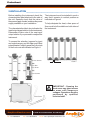
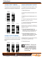
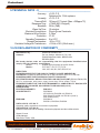
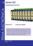
Datasheet
ISOLATED
SIGNAL
CONVERTER
ISC Series
SIGNAL CONVERTERS
FEMA ELECTRÓNICA
WITH GALVANIC ISOLATION
MODEL
ISC-P for Process
HT1102r150908
USER’S MANUAL
FEMA ELECTRÓNICA - Page 1
AmpliconBenelux.com
Tel: +31 105298827
[email protected]
www.fema.es
IT and Instrumentation for Industry
Fax: +31 105298828
Email: [email protected]
BENELUX
Datasheet
1-GENERAL INFORMATION___________________________________
The ISC series of Isolated Signal Converters,
allow to convert process signals,
temperatures, electrical signals, etc, to current
loops or voltage signals for further
retransmision, while introducing into the
system galvanic isolation barriers between
the input, the output and the power supply
circuits.
The ISC series of Isolated Signal Converters,
offer an excellent relation between signal
conversion speed and measurement
accuracy. Offering a 0.2% accuracy and up
to a 70ms response time depending on the
model, these units can process information
coming from probes or transducers, in such
a way that can be quickly retransmitted in a
fast and accurate form to remote data
acquisition systems or PLC’s. The isolated
signal converters of the ISC series are ideal
to integrate into 12 bit data acquisition
systems.
Its powerful galvanic isolation of 3.500 V
introduces high security to the measuring
systems, preventing the propagation of those
phenomenon which usually cause damage
to the remote system, such as transient
peaks or energy shocks in any of the circuits
of the system. The galvanic isolation also
acts as a strong CE barrier. The decoupling
created between the input, output and power
circuits avoids pernicious effects on the
output, such as ground loops or signal leaks,
which distort the acquired data and are
extremely difficult to isolate once introduced
into the signal.
AmpliconBenelux.com
Tel: +31 105298827
The isolation offered by the ISC series of
Isolated Signal Converters is a 3 way
isolation. Thus, all the benefits exposed
above are applicable to any of the three
circuits composing the instrument : input,
output and power.
Recalibration of the instruments is realized
in a fast and easy way. Opening the front
cover grants access to the configuration
jumpers. Additional Span and Offset
potentiometers are directly accessible from
the frontal part. These potentiometers are
highly decoupled, minimizing the iterations
needed to obtain a correct adjustment.
In order to obtain a higher and quickest
benefit of the ISC units, we recommend you
to read carefully the information provided in
this manual before proceeding to the
installation of the instrument. In this manual
you will find all technical data, both electrical
and mechanical, needed for a correct
instalation and utilization.
Note : The ISC Isolated Signal Converter
instruments have a characteristics label
attached on the side of the instrument. Check
that the information indicated on the label
matches with your application requirements,
and specially check that the value and type of
the power supply needed matches the value
and type of the power supply availble on your
installation.
IT and Instrumentation for Industry
Fax: +31 105298828
Email: [email protected]
BENELUX
Datasheet
2-INSTALLATION____________________________________________
Before installing the instrument check the
characteristics label attached to the side of
the unit. Specially check that the value of
the power supply needed, matches the power
supply available on your installation.
The characteristics label also indicates the
input/output signal relation for the instrument.
Remember to take note of the new input/
output relation if you proceed to readjust the
instrument.
The instrument must be installed in such a
way that it remains in vertical position as
indicated on Figure4.
To help dissipate the heat, a free space of
2mm must be left available on both sides of
the instrument.
To access the selection jumpers for input
and output ranges, and the Span and Offset
potentiometers, slightly press the A-A points
of the front cover as indicated on Figure1.
J1
J2
J3
J4
J5
J6
OUTPUT JUMPERS
2 mm
FIGURE 4
POT. SPAN
POT. OFFSET
J7
J8
J9
J10
J11
J12
INPUT JUMPERS
FIGURE 2
FIGURE 1
FRONT COVER
IMPORTANT - Opening the
front cover may grant access
to areas with dangerous
voltages. Operations must be
performed by qualified
technical staff.
FIGURE 3
AmpliconBenelux.com
Tel: +31 105298827
IT and Instrumentation for Industry
Fax: +31 105298828
Email: [email protected]
BENELUX
Datasheet
3-DIMENSIONS AND CONNECTIONS____________________________
Output Connections
Input Connections
VOLTAGE OR CURRENT
GENERATOR
HOUSING WIDTH FOR
AC POWERED
INSTRUMENTS
DC POWERED
CONNECTIONS
24 VDC
3 WIRE
TRANSDUCER
2 WIRE
TRANSDUCER
AC POWERED
CONNECTIONS
~
0 VDC
~
9mm
(0.35’’)
321
110 mm
(4.33’’)
37mm (1.46’’)
AmpliconBenelux.com
Tel: +31 105298827
93mm
(3.66’’)
22.5mm (0.87’’)
IT and Instrumentation for Industry
Fax: +31 105298828
Email: [email protected]
BENELUX
Datasheet
4-SIGNAL INPUT JUMPERS_____
6-READJUSTING INPUT / OUTPUT
The position of the input jumpers selects the
range for the input signal as indicated below.
To change the input/output relation of the
instrument, proceed as indicated below :
1.- Open the front cover
0/20mA
4/20mA
0/10 VDC
2.- Select the required input jumpers (Section
4, page 6)
J7
J8
3.- Select the required output jumpers (Section
J9
5, page 6)
J10
4.- Connect a signal generator to the input
terminals (8 signal and 9 common)
J11
J12
0/50 mA
10/50 mA
0/5 mA
1/5 mA
5.- Connect a multimeter to the output terminals
(4 and 5 for mA or 4 and 6 for Vdc)
0/1 VDC
(Following values in brackets are examples for
readjusting the input/output relation of the instrument
to 4/20mA = 0/10 Vdc)
J7
J8
J9
6.- Generate the low input signal (4mA)
Operate the OFFSET potentiometer, until
the low output value is reached (0Vdc)
J10
J11
J12
5-SIGNAL OUTPUT JUMPERS___
The position of the output jumpers selects
the range for the output signal as indicated
below.
4/20 mA
0/20 mA
0/10 VDC
7.- Generate the high input signal (20mA)
Operate the SPAN potentiometer, until the
high output value is reached (10Vdc)
8.- Repeat 6 and 7 to improve the accuracy
until it reaches its specified value
9.- Close the front cover
0/1 VDC
J1
IMPORTANT - Opening the
front cover may grant access
to areas with dangerous
voltages. Operations must be
performed by qualified
technical staff.
J2
J3
J4
J5
J6
AmpliconBenelux.com
Tel: +31 105298827
IT and Instrumentation for Industry
Fax: +31 105298828
Email: [email protected]
BENELUX
Datasheet
7-CALCULATING POSSIBLE ADJUSTMENTS____________________
Use the formulas below to find if an input/
output relation is possible on the
instrument. Formulas are based on the
input and output signals desired, and the
input and output ranges selectable on the
instrument.These parameters are defined
as [IL] (Input Low), [IH] (Input High), [OL]
(Output Low), [OH] (Output High), [IR]
(Input Range) and [OR] (Output Range).
Signal Input
from [IL]
to
[IH]
in mA or Vdc
Signal Output
from [OL]
to
[OH] in mA or Vdc
Input Range
select the input range [IR] from the following options
20mA, 50mA, 5mA , 10Vdc, 1Vdc
Output Range
select the output range [OR] from the following options
10Vdc, 20mA, 1Vdc
SPAN Value
SPAN =
[IR]
x [OH] - [OL]
[IH] - [IL]
[OR]
SPAN>2
Adjust NOT possible
0.5<SPAN<2
Adjust possibe
0.05<SPAN<0.5
Adjust possible, but select the Output
Selection Jumpers J5 and J6 as indicated
while J1, J2, J3 and J4 remain as indicated
in section 5
J1
J2
J3
J4
J5
J6
OFFSET Value
OFFSET =
OFFSET >0.5
[OL]
[OR]
-
[IL]
[IR]
x SPAN
Adjust NOT possible
-0.5<OFFSET<0.5 Adjust possibe
OFFSET <-0.5
AmpliconBenelux.com
Tel: +31 105298827
Adjust NOT possible
IT and Instrumentation for Industry
Fax: +31 105298828
Email: [email protected]
BENELUX
Datasheet
8-TECHNICAL DATA - I_______________________________________
INPUT SIGNAL in Vdc
RANGES
0/10Vdc
0/1Vdc
MECHANICAL DIMENSIONS
INPUT SIGNAL in mA
RANGES
0/20mA (4/20mA)
0/50mA (10/50mA)
0/5mA
OUTPUT SIGNAL in Vdc
RANGES
0/10Vdc
0/1Vdc
Maximum Output 11Vdc aprox.
Minimum Output -1Vdc aprox.
Minimum Load
≥1KOhm
DC Powered
AC Powered
Weight DC
Weight AC
22.5 x 93 x 110 mm
37.0 x 93 x 110 mm
120 gr.
200 gr.
Standard DIN rail mounting (DIN46277,
DIN EN 50022)
37,5 x 7,5 mm (1,38 x 0,3 ´´)
GALVANIC ISOLATION
OUTPUT SIGNAL in mA
RANGES
0/20mA (4/20mA)
Maximum Output 22mA aprox.
Minimum Output -1.5mA aprox.
Maximum Load ≤400 Ohms
IMPEDANCES and OVERVOLTAGES
Range
Zin
Max. Vdc
4/20 mA
50 Ohm
3.5 Vdc
0/20 mA
50 Ohm
3.5 Vdc
0/50 mA
20 Ohm
2.5 Vdc
0/5 mA
20 Ohm
2.5 Vdc
0/10 Vdc
5 MOhm
150 Vdc
0/1 Vdc
0/1 MOhm 15 Vdc
DC Powered Units
Input - Output
Power - Input
Power - Output
3K5 (60 seconds)
3K5 (60 seconds)
1KV (60 seconds)
AC Powered Units
Input - Output
Power - Input
Power - Output
3K5 (60 seconds)
3K5 (60 seconds)
3K5 (60 seconds)
All isolation levels are tested during a time
of 60 seconds, with Vac TrueRMS signal,
and current leaks <1mA
Note : Indicated isolation levels are also
sometimes named as STRENGTHENED
ISOLATION levels, for systems with
Polution Level 2
POWER SUPPLY
MATERIALS
DC Power
AC Power
Consumption
24Vdc ±10%
230Vac ±10% 50/60 Hz
115Vac ±10% 50/60 Hz
<3.8VA
AmpliconBenelux.com
Tel: +31 105298827
Box and Cover in Poliamide PA6 UL94 V2 blue color
Terminals in Poliamide UL94 V-0
IT and Instrumentation for Industry
Fax: +31 105298828
Email: [email protected]
BENELUX
Datasheet
9-TECHNICAL DATA - II______________________________________
Accuracy
Linearity
Thermal Drift
Response Time
Bandwith
Warm-Up Time
Electrical Connections
Maximum Wire Section
Protection
Operating Temperature
Storage Temperature
Excitation Voltage for Transducers
<0.2% F.S.
Optimized for 12 bit systems
<0.1% F.S.
150 ppm/ºC Typical (Max. <200ppm/ºC)
<70mS (90% of signal)
20Hz (-3dB)
15 minutes
Plug-in Screw Terminals
2.5 mm2
IP-30
0 to 60ºC
-20 to +70ºC
+15Vdc ±10% (22mA max.)
10-CE DECLARATION OF CONFORMITY________________________
Manufactured by :
Address:
FEMA ELECTRÓNICA, S.A.
Pol. Ind. Santiga - Altimira 14 (T14 - N2)
E 08210-Barberà del Vallès - BARCELONA
ESPAÑA - SPAIN
We hereby declare under our responsibility, that the equipments identified below
comply with the following specifications :
Series:
Isolated Signal Converter of the ISC Series
Models :
P, PT100, TJ, TK, TE, TT, TR, TS,
VAC, VDC, IAC, IDC, POT, RES, HZ, LC
DIRECTIVES
EUROPEAN DIRECTIVE FOR LOW VOLTAGE D73/23/CEE AMENDED BY
D93/68/CEE. Equipments powered from 50 to 1000 Vac and/or from 75 to 1500 Vdc.
EUROPEAN DIRECTIVE FOR PRODUCT SAFETY D92/59/CEE
ELECTROTECHNICAL REGULATION FOR LOW VOLTAGE (RBT) ITC21, ITC 29, ITC
35. For equipments with power supply lower than 50Vac and/or 75Vdc.
EUROPEAN DIRECTIVE FOR ELECTROMAGNETIC COMPATIBILITY D89/336/CEE
AMENDED BY D93/68CEE, ACCORDING TO RD1950/1995 (01/12)
REGULATIONS
ELECTRICAL SECURITY:
EN61010-1
SUSCEPTIBILITY:
EN 50082-2
IEC 1000-4-2, EN 61000-4-2, IEC 801-2
ENV 50140, EN 61000-4-4, IEC 801-4 (level 3)
ENV 50204 (level 3)
EMISSION:
EN 50081-2
EN 55011, EN 55014, EN 55022
UNE 21352-76: CEI 359-71
Operating quality expressions for electronic equipments.
UNE 20652-80: CEI 284-68
Behaviour rules inherent to the handling of electronic equipments and other similar technics.
Signed : D.Juncà
Quality Manager
Barberà del Vallès, 2002
AmpliconBenelux.com
Tel: +31 105298827
IT and Instrumentation for Industry
Fax: +31 105298828
Email: [email protected]
BENELUX