1
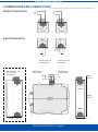
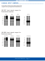
ISOLATED
SIGNAL
CONVERTER
Serie
ISC
SIGNAL CONVERTERS
FEMA ELECTRÓNICA
WITH GALVANIC ISOLATION
MODEL
ISC-POT for Potentiometers
ISC-RES for Resistances
USER’S MANUAL
HT0403r150908
FEMA ELECTRÓNICA - Page 1
[email protected]
www.fema.es
User’s Manual Series ISC
0-INDEX___________________________________________________
1-GENERAL INFORMATION .................................. 3
2-INSTALLATION ................................................... 4
3-DIMENSIONS AND CONNECTIONS ................... 5
4-SIGNAL INPUT JUMPERS .................................. 6
5-SIGNAL OUTPUT JUMPERS .............................. 7
6-READJUSTING INPUT/OUTPUT ......................... 7
7-TECHNICAL DATA-I ............................................ 8
INPUT SIGNAL for POTENTIOMETER ....... 8
INPUT SIGNAL for RESISTANCE .............. 8
OUTPUT SIGNAL in Vdc ........................... 8
OUTPUT SIGNAL in mA ............................ 8
POWER SUPPLY ..................................... 8
MECHANICAL DIMENSIONS .................... 8
GALVANIC ISOLATION ............................. 8
MATERIALS .............................................. 8
8-TECHNICAL DATA-II ........................................... 9
9-CE DECLARATION OF CONFORMITY ............... 9
10-CAUTIONS, WARNINGS AND NOTES ............. 10
11-WARRANTY ..................................................... 11
OTHER PRODUCTS .............................................. 12
FEMA ELECTRÓNICA - Page 2
User’s Manual Series ISC
1-GENERAL INFORMATION___________________________________
The ISC series of Isolated Signal Converters,
allow to convert process signals,
temperatures, electrical signals, etc, to current
loops or voltage signals for further
retransmision, while introducing into the
system galvanic isolation barriers between
the input, the output and the power supply
circuits.
The ISC series of Isolated Signal Converters,
offer an excellent relation between signal
conversion speed and measurement
accuracy. Offering a 0.2% accuracy and up
to a 70ms response time depending on the
model, these units can process information
coming from probes or transducers, in such
a way that can be quickly retransmitted in a
fast and accurate form to remote data
acquisition systems or PLC’s. The isolated
signal converters of the ISC series are ideal
to integrate into 12 bit data acquisition
systems.
Its powerful galvanic isolation of 3.500 V
introduces high security to the measuring
systems, preventing the propagation of those
phenomenon which usually cause damage
to the remote system, such as transient
peaks or energy shocks in any of the circuits
of the system. The galvanic isolation also
acts as a strong CE barrier. The decoupling
created between the input, output and power
circuits avoids pernicious effects on the
output, such as ground loops or signal leaks,
which distort the acquired data and are
extremely difficult to isolate once introduced
into the signal.
The isolation offered by the ISC series of
Isolated Signal Converters is a 3 way
isolation. Thus, all the benefits exposed
above are applicable to any of the three
circuits composing the instrument : input,
output and power.
Recalibration of the instruments is realized
in a fast and easy way. Opening the front
cover grants access to the configuration
jumpers. Additional Span and Offset
potentiometers are directly accessible from
the frontal part. These potentiometers are
highly decoupled, minimizing the iterations
needed to obtain a correct adjustment.
In order to obtain a higher and quickest
benefit of the ISC units, we recommend you
to read carefully the information provided in
this manual before proceeding to the
installation of the instrument. In this manual
you will find all technical data, both electrical
and mechanical, needed for a correct
instalation and utilization.
Note : The ISC Isolated Signal Converter
instruments have a characteristics label
attached on the side of the instrument. Check
that the information indicated on the label
matches with your application requirements,
and specially check that the value and type of
the power supply needed matches the value
and type of the power supply availble on your
installation.
FEMA ELECTRÓNICA - Page 3
User’s Manual Series ISC
2-INSTALLATION____________________________________________
Before installing the instrument check the
characteristics label attached to the side of
the unit. Specially check that the value of
the power supply needed, matches the power
supply available on your installation.
The characteristics label also indicates the
input/output signal relation for the instrument.
Remember to take note of the new input/
output relation if you proceed to readjust the
instrument.
The instrument must be installed in such a
way that it remains in vertical position as
indicated on Figure4.
To help dissipate the heat, a free space of
2mm must be left available on both sides of
the instrument.
To access the selection jumpers for input
and output ranges, and the Span and Offset
potentiometers, slightly press the A-A points
of the front cover as indicated on Figure1.
OUTPUT JUMPERS
J1
J2
J3
J4
J5
J6
2 mm
FIGURE 4
POT. SPAN
POT. OFFSET
J7
J8
J9
J10
J11
J12
INPUT JUMPERS
FIGURE 2
FIGURE 1
FRONT COVER
IMPORTANT - Opening the
front cover may grant access
to areas with dangerous
voltages. Operations must be
performed by qualified
technical staff.
FIGURE 3
FEMA ELECTRÓNICA - Page 4
User’s Manual Series ISC
3-DIMENSIONS AND CONNECTIONS____________________________
Output Connections
Input Connections
C ABLE
SHIELD
CONNECTIONS FOR
POTENTIOMETER
HOUSING WIDTH FOR
AC POWERED
INSTRUMENTS
DC POWERED
CONNECTIONS
24 VDC
CONNECTIONS FOR
RESISTANCE
AC POWERED
CONNECTIONS
~
~
0 VDC
9mm
(0.35’’)
321
110 mm
(4.33’’)
37mm (1.46’’)
93mm
(3.66’’)
22.5mm (0.87’’)
FEMA ELECTRÓNICA - Page 5
User’s Manual Series ISC
4-SIGNAL INPUT JUMPERS___________________________________
The position of the input jumpers selects the
range for the input signal as indicated below.
ISC-POT Input signal ranges for
Potentiometer measure
100%
50%
12.5%
25%
J7
J7
J8
J8
J9
J9
J10
J10
J11
J11
J12
J12
ISC-RES Input signal ranges for
Resistance measure
10 KOhms
5 KOhms
3 KOhms
1,5 KOhms
J7
J7
J8
J8
J9
J9
J10
J10
J11
J11
J12
J12
FEMA ELECTRÓNICA - Page 6
User’s Manual Series ISC
5-SIGNAL OUTPUT JUMPERS___
6-READJUSTING INPUT / OUTPUT
The position of the output jumpers selects
the range for the output signal as indicated
below.
To change the input/output relation of the
instrument, proceed as indicated below :
4/20 mA
0/20 mA
0/10 VDC
0/1 VDC
J1
(Following values in brackets are examples for
readjusting the input/output relation of the instrument
to 0/100% = 0/10 Vdc and input type potentiometer)
1.- Open the front cover
J2
J3
2.- Select the required input jumpers (Section
J4
4, page 6)
J5
3.- Select the required output jumpers (Section
J6
5, page 7)
4.- Connect a potentiometer to the input
terminals (Section 3, page 5)
5.- Connect a multimeter to the output terminals
(4 and 5 for mA or 4 and 6 for Vdc)
6.- Generate the low input signal (0%)
Operate the OFFSET potentiometer, until
the low output value is reached (0Vdc)
7.- Generate the high input signal (100%)
Operate the SPAN potentiometer, until the
high output value is reached (10Vdc)
8.- Repeat 6 and 7 to improve the accuracy
until it reaches its specified value
9.- Close the front cover
IMPORTANT - Opening the
front cover may grant access
to areas with dangerous
voltages. Operations must be
performed by qualified
technical staff.
FEMA ELECTRÓNICA - Page 7
User’s Manual Series ISC
7-TECHNICAL DATA - I_______________________________________
INPUT SIGNAL for POTENTIOMETER
RANGES
0/100%
0/50%
0/25%
0/12.5%
POWER SUPPLY
DC Power
24Vdc ±10%
AC Power
230Vac ±10% 50/60 Hz
115Vac ±10% 50/60 Hz
Consumption
<3.8VA
POTENCIOMETER VALUES
Minimum
100 Ohms
Maximum
1 MOhm
MECHANICAL DIMENSIONS
DC Powered
22.5 x 93 x 110 mm
AC Powered
37.0 x 93 x 110 mm
Weight DC
120 gr.
Weight AC
200 gr.
POTENTIOMETER EXCITATION TO
MEASURE
1 Vdc
Standard DIN rail mounting (DIN46277,
DIN EN 50022)
37,5 x 7,5 mm (1,38 x 0,3 ´´)
INPUT SIGNAL for RESISTANCE
RANGES
0/10 KOhms
0/5 KOhms
0/3 KOhms
0/1.5 KOhms
RESISTANCE EXCITATION
MEASURE
0.2 mA
TO
MÁXIMUM VOLTAGE ON INPUT
TERMINALS
15 Vdc differential
OUTPUT SIGNAL in Vdc
RANGES
0/10Vdc
0/1Vdc
Maximum Output 11Vdc aprox.
Minimum Output -1Vdc aprox.
Minimum Load
≥1KOhm
OUTPUT SIGNAL in mA
RANGES
0/20mA (4/20mA)
Maximum Output 22mA aprox.
Minimum Output -1.5mA aprox.
Maximum Load ≤400 Ohms
GALVANIC ISOLATION
DC Powered Units
Input - Output
3K5 (60 seconds)
Power - Input
3K5 (60 seconds)
Power - Output
1KV (60 seconds)
AC Powered Units
Input - Output
Power - Input
Power - Output
3K5 (60 seconds)
3K5 (60 seconds)
3K5 (60 seconds)
All isolation levels are tested during a time
of 60 seconds, with Vac TrueRMS signal,
and current leaks <1mA
Note : Indicated isolation levels are also
sometimes named as STRENGTHENED
ISOLATION levels, for systems with
Polution Level 2
MATERIALS
Box and Cover in Poliamide PA6 UL94 V2 blue color
Terminals in Poliamide UL94 V-0
FEMA ELECTRÓNICA - Page 8
User’s Manual Series ISC
8-TECHNICAL DATA - II______________________________________
Accuracy
Linearity
Thermal Drift
Response Time
Warm-Up Time
Electrical Connections
Maximum Wire Section
Protection
Operating Temperature
Storage Temperature
<0.2% F.S.
Optimized for 12 bit systems
<0.1% F.S.
250 ppm/ºC Typical
<70mS (90% of signal) (3Hz -3dB)
15 minutes
Plug-in Screw Terminals
2.5 mm2
IP-30
0 to 60ºC
-20 to +70ºC
9-CE DECLARATION OF CONFORMITY________________________
Manufactured by :
Address:
FEMA ELECTRÓNICA, S.A.
Pol. Ind. Santiga - Altimira 14 (T14 - N2)
E 08210-Barberà del Vallès - BARCELONA
ESPAÑA - SPAIN
We hereby declare under our responsibility, that the equipments identified below
comply with the following specifications :
Series:
Isolated Signal Converter of the ISC Series
Models :
P, PT100, TJ, TK, TE, TT, TR, TS,
VAC, VDC, IAC, IDC, POT, RES, HZ, LC
DIRECTIVES
EUROPEAN DIRECTIVE FOR LOW VOLTAGE D73/23/CEE AMENDED BY
D93/68/CEE. Equipments powered from 50 to 1000 Vac and/or from 75 to 1500 Vdc.
EUROPEAN DIRECTIVE FOR PRODUCT SAFETY D92/59/CEE
ELECTROTECHNICAL REGULATION FOR LOW VOLTAGE (RBT) ITC21, ITC 29, ITC
35. For equipments with power supply lower than 50Vac and/or 75Vdc.
EUROPEAN DIRECTIVE FOR ELECTROMAGNETIC COMPATIBILITY D89/336/CEE
AMENDED BY D93/68CEE, ACCORDING TO RD1950/1995 (01/12)
REGULATIONS
ELECTRICAL SECURITY:
EN61010-1
SUSCEPTIBILITY:
EN 50082-2
IEC 1000-4-2, EN 61000-4-2, IEC 801-2
ENV 50140, EN 61000-4-4, IEC 801-4 (level 3)
ENV 50204 (level 3)
EMISSION:
EN 50081-2
EN 55011, EN 55014, EN 55022
UNE 21352-76: CEI 359-71
Operating quality expressions for electronic equipments.
UNE 20652-80: CEI 284-68
Behaviour rules inherent to the handling of electronic equipments and other similar technics.
Signed : D.Juncà
Quality Manager
Barberà del Vallès, 2002
FEMA ELECTRÓNICA - Page 9
User’s Manual Series ISC
10-CAUTIONS, WARNINGS AND NOTES
INSTALLATION
PRECAUTIONS.- The installation and the
future use of this unit must
be done by qualified
personnel. The unit has not
AC (mains) switch, neither
internal protection fuse. It will be in operation
as soon as power is connected. The
installation must incorporate an external
mains switch with a protection fuse and also
the necessary devices to protect the operator
and the process when using the unit to a
control machine or process where injury to
personnel or damage to equipment or
process may occur as a result of failure of
the unit.
RECOMMENDED FUSES
24Vdc
230Vac
115Vac
250mA
70mA
100mA
Time-lag Time-lag
Time-lag
SAFETY PRESCRIPTIONS.- The unit has
been designed and tested under
EN-61010-1 rules and is
delivered in good conditions.
This User’s Manual contains
useful information the user has to respect in
order to warrant a proper function of the unit,
and good security conditions. The unit is
designed for internal applications, with
good ventilation to avoid excessive heating.
It can occasionally be applied to
temperatures down to 10ºC or up to 70ºC
without security degradation. Do all
connections before applying power to the
unit. Do not make wiring changes until
power is disconnected from the unit.
Install the unit far from elements generating
electric noise, or magnetic fields, such as
power relays, electrical engines, speed
regulators, etc. Do not use until installation
is completed.
POWER SUPPLY.- The power supply must
be connected to the adequate terminals 1,
2 and 3. The characteristics of the power
supply are shown on the side label. Please
make sure that the unit is correctly
connected to a power supply of the correct
voltage and frequency. Do not connect the
unit to lines which are overloaded or which
provide power to systems working on ONOFF cycles or inductive loads.
ATTENTION
For instruments which are DC powered,
respect the polarity of the power terminals
as indicated on this user’s manual, and on
the instrument itself.
SIGNAL WIRING .- Certain considerations
must be given when installing the signal
input wires. If the wires are long, they can act
as an antenna introducing electrical noise
into the unit. Therefore :
- Do not install the signal input wires in
the same conduit with power lines, heaters,
solenoids, SCR controls, etc ... and always
far from these elements.
- When shielded wires are used, leave
unconnected the shield on the transmitter
side and connect the other end of the shield
to the ground terminal of the machine.
EXCITATION VOLTAGE
Model ISC-P incorporates an internal power
supply for transducers. The output of this
power supply is connected to terminals 7
and 9. Do not connect these terminals to an
external power supply, beacuse both units
will be permantently damaged.
FEMA ELECTRÓNICA - Page 10
User’s Manual Series ISC
SAFETY CONSIDERATIONS
PRESCRIPTION.- Before starting any
operation for replacement, maintenance or
repair, the unit must be
disconnected from any kind
of power supply.
Keep the unit clean, to
assure good functioning and performance.
To prevent electrical or fire hazard, do not
expose the unit to excessive moisture. Do not
operate the unit in the presence of flammable
gases or fumes, such an environment
definetely constitutes a safety hazard. The
unit is designed to be mounted on a metal
panel.
If the unit shows signs of damage, is not able
to show the expected measures, has been
stored in a bad conditions or a protection
failure happened, then do not attempt to
operate, keep the unit out of service and send
for repair.
IN CASE OF FIRE
1.- Disconnect the unit from the power supply
2.- Give the alarm according to the local rules
3.- Switch off all air conditioning devices
4.- Attack the fire with carbonic
snow, do not use water in any
case
WARNING: In closed areas do not use
systems with vaporized liquids.
11-WARRANTY___________________________________________
FEMA ELECTRÓNICA, S.A. warrants this unit
to be free of manufacturing defects for a period
of 24 MONTHS from shipment date. This
warranty covers both materials and
manufacturing processes.
This warranty is VOID if the unit shows evidence
of damages as a result of misapplication,
accident, misuse or if the product had been
tampered or repaired by personnel or
companies without the official authorization of
FEMA ELECTRÓNICA, S.A. This warranty is
also VOID for damages caused by defective or
inappropriate applications.
RETURNS FOR REPAIR
Ship free of charges and properly packed to
the address indicated below :
In case of malfunction, the unit should be sent
to the manufacturer for its evaluation. Within
the warranty period, and always previous
examination from FEMA ELECTRÓNICA, S.A.,
the unit will be repaired or replaced to the
discretion of the manufacturer.
Limitation of liability : FEMA ELECTRÓNICA,
S.A. shall not be responsible for any damage
or loss to other equipment however caused,
which may be experienced as a result of the
installation or use of this product. FEMA ELECTRÓNICA, S.A. liability shall not exceed the
purchase price paid of the product upon which
liability is based. In no event shall FEMA
ELECTRÓNICA, S.A. be liable for
consequential, inicidental or special
damages
FEMA ELECTRÓNICA, S.A.
Pol.Ind.Santiga - Altimira 14 (T-14 N-2)
E-08210 Barberà del Vallés - BARCELONA
ESPAÑA - SPAIN
FEMA ELECTRÓNICA - Page 11
other products
Programmable
Panel Meters
Signal Converters &
Isolated Transmitters
Large Displays
Standard
Panel Meters
Miniature
Panel Meters
Large Displays
for TIME
www.fema.es
ELECTRONIC INSTRUMENTATION FOR INDUSTRY
FEMA ELECTRÓNICA, S.A.
Pol. Ind. Santiga - Altimira 14 (T14 - N2)
E-08210 Barberà - BARCELONA
ESPAÑA - SPAIN
Tel. (+34) 93.729.6004 - www.fema.es
FEMA ELECTRÓNICA - Page
Fax (+34) 93.729.6003 - [email protected]
12