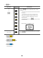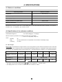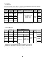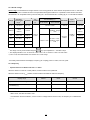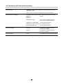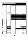
1
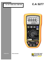
AC+DC TRMS MULTIMETER ENGLISH User’s manual C.A 5277 PRECAUTIONS FOR USE This instrument is compliant with the NF EN 61010-1 + NF EN 61010-2-030 safety standard for 1000 V voltages in category III or 600 V in category IV at an altitude below 2000 m, indoors, and with a maximum pollution level of 2. Failure to comply with safety instructions can create a risk of electric shock, fire, explosion and destruction of the instrument or the installations. Do not use the instrument in an explosive atmosphere or in the presence of inflammable gas or smoke. Do not use the instrument on networks with a rated voltage or category higher than those mentioned. Respect the maximum rated voltages and currents between terminals and in relation to the earth. Do not use the instrument if it seems damaged, incomplete or incorrectly closed. Before each use, check the condition of the cable insulation, the unit and the accessories. All elements on which the insulation is damaged (even partially) must be put out of service for repair or disposed of as waste. Use cables and accessories for voltages according to IEC 61010-031 and measurement categories at least equal to those of the instrument. Respect the environmental conditions of use. Strictly comply with the fuse specifications. Disconnect all cables before opening the fuse access cover. Do not modify the instrument and do not replace components using equivalent parts. Repairs and adjustments must be carried out by qualified, approved personnel. symbol appears on the display. Disconnect all cables before opening the Replace the battery as soon as the battery access cover. Use personal protection equipment when conditions require it. Do not place your hands close to instrument terminals that are in use. When handling sensors or test probes, do not place fingers beyond the physical finger guard. MEASUREMENT CATEGORIES CAT II: Test and measurement circuits directly connected to points of use (power outlets and other similar points) on the low-voltage network. E.g. Measurements on circuits in network for household appliances, portable tools and other similar instruments. CAT III: Test and measurement circuits connected to parts of the building's low-voltage network installation. E.g. Measurements on distribution switchboards (including secondary meters), the circuit breakers, cabling including cables, busbars, junction boxes, circuit breakers, power outlets in the fixed installation and industrial instruments and other equipment such as motors permanently connected to the fixed installation CAT IV: Test and measurement circuits connected to the source of the building's low-voltage network installation. E.g. Measurement on equipment installed upstream of the main fuse or building installation cut-off switch. You have just purchased a C.A 5277 multimeter and we thank you for your confidence in our products. To obtain the best service from your instrument: Read these instructions carefully; Respect the precautions for use. Meanings of the symbols used on the instrument. Danger hazard: The operator undertakes to consult these instructions each time this danger hazard symbol is encountered. Fuse 9V Battery The CE marking certifies compliance with European directives. Double or strengthened insulation Waste sorting for the recycling of electric and electronic waste in the European Union AC - Alternating current AC and DC - Alternating and direct current Earth Risk of electric shock 2 CONTENTS 1. OVERVIEW .........................................................................................................................................................3 1.1 The display ............................................................................................................................................4 1.2. The keys ................................................................................................................................................6 1.3. The switch..............................................................................................................................................6 1.4. The terminals .........................................................................................................................................7 2. Use ......................................................................................................................................................................7 2.1 First use .................................................................................................................................................7 2.2 Starting up the multimeter .....................................................................................................................7 2.3 Turning off the multimeter......................................................................................................................7 2.4 The stand...............................................................................................................................................7 3. Functions............................................................................................................................................................8 3.1 Switch functions.....................................................................................................................................8 3.2 Key functions .......................................................................................................................................14 4. Specifications ..................................................................................................................................................24 4.1 Reference conditions ...........................................................................................................................24 4.2 Specifications of the reference conditions ...........................................................................................24 4.3 Operating conditions............................................................................................................................31 4.4 Construction specifications..................................................................................................................31 4.5 Power supply .......................................................................................................................................31 4.6 Compliance with international standards.............................................................................................32 4.7 Variations in the field of use ................................................................................................................33 5. Maintenance .....................................................................................................................................................34 5.1 Cleaning...............................................................................................................................................34 5.2 Replacing the battery...........................................................................................................................34 5.3 Replacing the fuses .............................................................................................................................34 5.4 Metrology verification...........................................................................................................................34 5.5 Repair ..................................................................................................................................................34 6. Warranty ...........................................................................................................................................................35 7. To order ............................................................................................................................................................35 3 1. OVERVIEW The C.A 5277 is a stand-alone portable digital multimeter specially designed to combine all the functions for measurement of the following electrical quantities in a single instrument: AC Voltage measurement with low input impedance (voltage measurements for electrical and electrical engineering applications) AC and/or DC voltage measurement with high input impedance (voltage measurement for electronics) Frequency measurement Resistance measurement Audible continuity measurement Measurement and testing of semiconductor junctions Capacitance measurement AC and/or DC current measurement Temperature measurement in C ° or F ° by linearisation of the voltage on the terminals of a K thermocouple. 1.1 The display The multimeter's display allows users to: Display the functions: Show an analogue view of the measured parameter by means of the bargraph: Read the data comfortably thanks to the backlighting. , , , , , , , ; 1 2 9 3 4 5 6 7 8 Figure 1 : the display N°. Function 1 Bargraph 2 Main display (values and measurement units) 3 Type of measurement 4 Selection of the measurement scale. 5 Low-battery indicator 6 Audible continuity measurement Measurement and testing of semiconductor junctions 7 Display of selected modes 8 Secondary display used for: ¾ voltage measurement ¾ current measurement ¾ temperature measurement ¾ MAX/MIN/PEAK modes ¾ REL mode ¾ frequency measurement 9 Permanent mode: automatic instrument shut-down deactivated 4 1.1.1 The display symbols Symbols Description AC Measurement of the AC signal DC Measurement of the DC signal AC + DC Measurement of the AC and DC signal AUTO Auto-ranging Δ REL Relative values compared with a reference Δ MEM Presence of a relative value in memory HOLD Memorisation and display of memorised values MAX Maximum RMS value MIN Minimum RMS value PEAK+ Maximum peak value PEAK- Minimum peak value .run r.un ru.n Capacitance meter, acquisition in progress ----- Frequency measurement impossible O.L Measurement capacities exceeded V Volt Hz Hertz F Farad °C °F Degrees Celsius - Degrees Fahrenheit A Ampere % Percentage Ω Ohm n Symbol of the nano- prefix µ Symbol of the micro- prefix m Symbol of the milli- prefix k Symbol of the kilo- prefix M Symbol of the mega- prefix Audible continuity measurement symbol Symbol for measurement and testing of semiconductor junctions Permanent mode Low-battery indicator 1.1.2 Measurement capacities exceeded (O.L) O.L (Over Load) is displayed when the measured signal exceeds the capacity of the instrument's scale. If the manual RANGE mode is active, press the There are two exceptions: • 1000 V voltage range • 10 A range key to change the scale and then carry out the measurement. "OL" from 1050 V "OL" from 20 A 1.1.3 Automatic change of measurement range The AUTO symbol on the display indicates that the instrument automatically changes the measurement range to make the measurement. You can manually change the range by pressing 5 . 1.2. The keys The keyboard has five keys: MODE AC/DC, RANGE, MAX/MIN/PEAK, ΔREL and HOLD. These are the keys: 1 2 3 4 5 Figure 2: the keyboard keys N°. Function 1 Selection of the display mode. 2 Selection of the measurement scale and activation/deactivation of the screen backlighting ( 3 Activation of the MAX/MIN/PEAK mode 4 Memorisation of the values and display mode Activation or deactivation of the automatic instrument shut-down 5 Activation of the relative display mode. 1.3. The switch The switch has ten positions. The functions are described in the table below: 5 6 4 7 3 8 2 1 9 10 Figure 3: the switch N° 1 and 10 Function OFF Mode - Multimeter shut down 2 Voltage measurement with low impedance (VLowZ) 3 AC, DC or AC+DC voltage measurement with high impedance (V) 4 Frequency measurement (Hz) 5 Resistance measurement (Ω) Audible continuity measurement Diode test 6 Capacitance measurement (µF) 7 Temperature measurement (T °) 8 AC, DC or AC+DC current measurement (µA or mA) 9 AC, DC or AC+DC current measurement (A) 6 ) 1.4. The terminals These are the multimeter terminals: N°. 1 3 2 4 Input 1 6 A, 10 A current 2 20 µA, 6000 µA, 60 mA, 600 mA current 3 Other measurements 4 Common Figure 4: the terminals The terminals can be used to carry out the measurements using test-probe leads or the temperature sensor shipped with the instrument. The connection principles are described in paragraph 3. 2. USE 2.1 First use Fit the battery shipped with the instrument as follows: 1. Using a screw driver, unscrew the four screws on the cover (item 1) located at the rear of the unit; 2. Place the battery in its housing (item 2) while respecting the polarity; 3. Screw the cover back on. 1 2 Figure 5: access to the battery 2.2 Starting up the multimeter The switch is in the OFF position. Turn the switch to the function of your choice. All the display segments appear for a few seconds, then the screen for the selected function is displayed. The multimeter is now ready for measurements. 2.3 Turning off the multimeter The multimeter can be turned off either manually by returning the switch to the OFF position, or automatically after ten minutes without use. After nine minutes an intermittent sound alarm is triggered until the instrument is shut down. Once the instrument is shut down, to reactivate it press the cancels the active functions. key or turn the switch by at least one position. The latter method 2.4 The stand There are two stand positions, one for suspending the multimeter (position 1) and the other providing a stand (position 2). To change the stand position, proceed as follows: Position 1: fit the stand studs into the upper holes located on the rear of the unit: Position 2: fit the stand studs into the lower holes located on the rear of the unit: 7 3. FUNCTIONS 3.1 Switch functions To access the , , , , , , or , function position. Every position (except OFF) is confirmed by a beep. function, turn the switch to the selected 3.1.1 Types of measurements Below are the possible combinations depending on the type of measurement: Measurement type LowZ AC, AC, AC, AC+DC, DC, DC, AC+DC, AC, 20 µA DC 60 mV AC, 60 mV AC + DC Peak+ ΔRel 9 9 9 9 - 9 Auto / Range ΔREL only 9 9 9 9 - 9 9 - 9 9 9 9 - 9 9 - 9 9 - 9 9 9 - 9 9 AC+DC DC 60 mV DC, Max / Min ΔREL only 9 9 3.1.2 Voltage measurement The instrument measures the following types of voltages: DC voltage with high impedance (DC); AC voltage with high impedance (AC); DC voltage and AC voltage with high impedance (AC+DC); AC voltage with low impedance (VLowZ) In all cases "O.L " displays in excess of 1050 V and a beep sounds when the measurement exceeds 600 V. Volt VLowZ : This position is designed for measurements on electrical installations. The input impedance < 1 MΩ is used to avoid measuring "phantom" voltages caused by coupling between the lines. Thanks to the low pass filter, it is possible to measure the RMS voltage supplied by an MLI variable speed drive (for asynchronous motors). In VLowZ, the measurement signal goes through the low pass filter with a cut-off frequency of < 300 Hz. When measuring a voltage with a frequency in excess of 150 Hz, it is considerably reduced and therefore a significant error can occur. In this case the position which uses the entire bandwidth should be used. 8 To measure a voltage, proceed as follows: 1. Set the switch to or ; 2. Select the type of signal (AC, DC or AC+DC) by pressing . Depending on your selection, the screen will display AC, DC or AC+DC 3. Connect the black lead to the COM terminal and the red lead to "+"; 4. Place the test probes on the terminals of the circuit to be measured; 5. Read the measurement indicated on the display 6. By default, the 2nd display indicates the frequency, except for DC. 3.1.3 Frequency measurement To measure the frequency, proceed as follows: 1. Set the switch to ; 2. Connect the black lead to the COM terminal and the red lead to "+"; 3. Place the test probes on the terminals of the circuit to be measured; 4. Read the measurement indicated on the display. 9 3.1.4 Resistance measurement To measure the resistance, proceed as follows: 1. Set the switch to ; 2. Connect the black lead to the COM terminal and the red lead to "+"; 3. Place the test probes on the terminals of the component; Remark: all resistance measurements must be performed with the power off. 4. Read the measurement indicated on the display. 5. "O.L" is displayed if the circuit is open. 3.1.5 Audible continuity measurement For audible continuity measurement, proceed as follows: 1. Set the switch to ; 2. Press symbol is displayed; . The 3. Connect the black lead to the COM terminal and the red lead to "+"; 4. Place the test probes on the terminals of the circuit to be measured; 5. Read the measurement indicated on the display. 6. The continuity beep sounds when R < 30 Ω ± 3 Ω. 7. "O.R" is displayed if the circuit is open. 10 3.1.6 Diode test To measure and check a semiconductor junction, proceed as follows: ; 1. Set the switch to 2. Press twice on . The symbol is displayed; 3. Connect the black lead to the COM terminal and the red lead to "+"; 4. Place the test probes on the terminals of the component; 5. Read the junction threshold voltage measurement indicated on the display. 6. "O.L" is displayed if the circuit is open. 3.1.7 Capacitance measurement To measure the capacitance, proceed as follows: 1. Set the switch to ; 2. Connect the black lead to the COM terminal and the red lead to "+"; 3. Place the test probes on the terminals of the component; 4. Read the measurement indicated on the display. "O.L" is displayed if the value to be measured exceeds the capacitance of the range or if the capacitor is short-circuited. ¾ For high values, the measurement cycle includes the display of "run" with a "rolling" decimal point. This indicates that acquisition is in progress: wait for the display of the digital result. ¾ Prior discharge of very high capacitances helps to reduce the duration of the measurement. 11 3.1.8 Temperature measurement To measure the temperature, proceed as follows: 1. Set the switch to 2. Press ; to select the unit and scale of the temperature (° C or ° F). Remark: the default measurement unit displayed is ° C 3. Connect the temperature sensor to the COM and "+" terminals respecting the poles; 4. Read the measurement indicated on the display. 5. "O.L" is displayed the thermocouple is cut. NB: For greater accuracy, avoid subjecting the instrument to sudden temperature changes. 3.1.9 Current measurement To measure the current: Measurement in 1. Set the switch to ; . Depending on your selection, the screen will display 2. Select the type of signal (AC, DC or AC+DC) by pressing AC, DC or AC+DC 3. Connect the black lead to the COM terminal and the red lead to "µmA"; 4. Place the test probes in series between the source and the load; 5 Read the measurement indicated on the display. 6 By default, the 2nd display indicates the frequency, except for DC. NB: The 21 µA range, which can only be accessed using the key, is reserved for testing the ionisation sensors in gas-fired boilers. It is only available with DC coupling and the measurement is on 210 digits (0.1 µA resolution). 12 Measurement in 1. Set the switch to ; . Depending on your selection, the screen will display 2. Select the type of signal (AC, DC or AC+DC) by pressing AC, DC or AC+DC 3. Connect the black lead to the COM terminal and the red lead to "10A"; 4. Place the test probes in series on the circuit between the source and the load; 5. Read the measurement indicated on the display. 6. "O.L" is displayed if I > 20 A. 7. By default, the 2nd display indicates the frequency, except for DC. Detection of fuse tripping - or meltdown: If the fuse has melted, the circuit between COM and the 10 A socket is cut. The display shows « OL ».. 1. Set the switch to Ω. 2. Connect the V socket to the 10 A socket (see above); leave the "COM" socket free. 3. The display should show a result < 2 Ω, otherwise replace the fuse. 13 3.2 Key functions The functions: , , , , can be accessed by pressing a key repeatedly, using short or long presses. The long-press function is shown by the pictogram under the key. The functions are not exclusive, they can be combined. It is therefore possible to have min/max peak relative or just relative. In the same way, the Hold mode does not stop the min/max peak surveillance, it only freezes the display. Every push on a key is validated by a sound signal. In + mode In + + In + mode 3.2.1 See paragraph 3.2.4. mode See paragraph 3.2.1. See paragraph 3.2.4. Key Choice of AC/DC/AC+DC coupling or of the bargraph style, or second keyboard function (yellow). • In normal mode Type of press Resulting action short ¾ changes the type of measurement. There are three choices: AC, DC or AC+DC. The default coupling obtained following the selection of a quantity by the switch is AC+DC coupling; ¾ selects: on - audible continuity measurement ; - measurement and testing of a semiconductor junction . - return to resistance measurement ¾ displays the temperature in degrees Celsius (° C) or degrees Fahrenheit (° F). long DC on ¾ DC (> 2 sec) displays the bargraph with graduation from zero to the full scale or from zero to central ( DC 14 ). • In or + mode Resulting action Type of press short or long ¾ Displays the bar-graph with graduation from zero to full scale or central zero ( on ¾ ). Selects the display mode for the quantity measured, i.e.: - the relative measurement in the unit for the quantity measured: Measured quantity – reference (Δ) Remark 1: the REL symbol is displayed beneath the main unit of measurement. - the relative value (%) : measured quantity – reference (Δ) x 100 reference (Δ) Remark 2 : the % symbol is displayed to the right of the measurement value. Example: display screen 15 ΔREL in %. 3.2.2 Key This key is used to manually select a measurement range or to activate the screen backlighting. The range defines the maximum range for measurements performed with the instrument. Remark: the Auto Range mode is activated by default. • In normal mode Resulting action Type of press short ¾ on manually changes the measurement scale (extent and resolution). Example: In , mode, the screen displays: 59.00 V, range Auto When pressed the first time, the screen displays: 59.00 V, manual range (60 V range) the second time: 59.0 V, manual range (600 V range) the third time: 59 V, manual range (1000 V range) the fourth time: OL mV, manual range (60 mV range) the fifth time: OL mV, manual range (600 mV range) the sixth time: OL mV, manual range (6 V range) the seventh time: 59.00 V, Auto range (60 V range) the eighth time: 59.00 V, manual range (60 V range) The default mode is AUTO for each selection of a measurement type V, A etc. long (> 2 sec) on ¾ activates or deactivates the backlighting ( screen. 16 ) for the • In mode Resulting action Type of press short on ¾ exit from 17 mode. 3.2.3 Key This key displays the MAX, MIN, PEAK+ or PEAK- modes. Max and Min fill in the highest and lowest values of the measurement. Peak+ displays the instant maximum peak value and Peak- displays the instant minimum peak value for the measurement. • In normal mode Type of press Resulting action ¾ short on enters the MAX/MIN mode. Note that in permanent operation. is displayed Æ ¾ to select the quantities for MAX or MIN, PEAK+ or PEAK- Reminder: the MAX quantity is displayed by default. Example: display screen V / MAX. Example: display screen V / PEAK+ key freezes the displays without halting acquisition. NB: The The key quits the The key is active. mode long (> 2 sec) ¾ quits the mode. on Remark: Auto power off is automatically activated. 18 off. 3.2.4 Key This key is used to memorise the measurements and quantities or to deactivate the automatic power-off function on the instrument. • In normal mode Type of press Resulting action short ¾ memorises a measurement status at a given moment and then makes it possible to view them successively on the display. on ¾ If activated, the Min Max Peak acquisition continues as a background task. ¾ The bargraph continues to operate normally (even in Hold). ¾ In Hold, the ¾ exits from the ¾ activates or deactivates the auto power-off function on the instrument (AUTO OFF). When 'auto off' is deactivated the long (> 2 sec) keys can be used, mode. symbol is displayed. When auto power-off is activated, the display shows "APO on"; otherwise it displays "APO off". on 19 • In mode Type of press short Resulting action ¾ Example: display screen V HOLD ΔMEM. on long freezes the measured quantity and reference value; mode. ¾ quits the ¾ activates or deactivates the auto power-off function on the instrument (AUTO OFF). When 'auto off' is deactivated the symbol (> 2 sec) is displayed Æ Permanent operation. on ¾ When 'auto off' is activated, the second display temporarily indicates "APO on". ¾ When 'auto off' is activated, the second display temporarily indicates "APO off". 20 • In mode Type of press Resulting action short on ¾ freezes the display of each MAX, MIN, PEAK+ or PEAKquantity displayed. MAX, MIN, PEAK+ or PEAK- acquisition continues in the background. This is indicated by blinking of the MAX, MIN and PEAK symbols. Reminders: the max. quantity is displayed by default; - PEAK + and PEAK- are only available in VLowZ, V (AC, AC+DC), µA mA (AC, AC+DC) and A (AC, AC+DC). ¾ If you press a second time, you quit the 21 mode. 3.2.5 Key This key records and displays the measured quantity and the reference value or the relative measurement and the reference value. • In normal mode Resulting action Type of press short on ¾ ¾ ¾ ¾ The first short press records the measured value which will be the reference. The MEMΔ symbol indicates that the tare is recorded. The display indicates the relative measurement and the reference (Δ) value in the measurement unit for the quantity measured: The short presses that follow switch the display between relative (above ΔREL on) and normal (below ΔREL off) without changing the reference value. In all cases the reference value remains displayed. long (> 2 sec) on mode and clears the reference value. ¾ quits the The ΔMEM symbol is turned off. 22 • In mode Resulting action Type of press short ¾ applies the quantities. on function to the MAX, MIN, PEAK+ or PEAK- - The first short press records the measured value which will be the reference. - The following short presses switch the display between relative and normal without changing the reference value. - the relative measurement is displayed in the unit of the quantity measured. - The subsequent presses on the the reference value. key allow you to read Example: display screen V ΔMEM – MAX. ¾ quits the mode and clears the reference value. The ΔMEM symbol is turned off. long (> 2 sec) • In + mode See paragraph 3.2.1 • In + + mode See paragraph 3.2.1 • In + mode See paragraph 3.2.4 23 4. SPECIFICATIONS 4.1 Reference conditions Influencing quantities: Reference conditions Temperature 23° C ± 5° C Relative humidity 45 % to 75 % Power supply voltage 9V±1V Frequency domain of the applied signal 40 Hz to 1 kHz Absence of electric field NB: below, the accuracy is given as X % of the reading (R) ± Y counts (D). When the frequency exceeds 1 kHz, apply the formula X % R + Y % x [F (kHz) - 1] R ± D with F in kHz. 4.2 Specifications of the reference conditions Uncertainties are given in: X % of the reading (R) ± Y counts (D). When the frequency exceeds 1 kHz, apply the formula given in the tables X % R + Y % x [F (kHz) - 0.4] R ± D. where: - Reading "R", - Digit "D", the measurement count equivalent to the resolution of the display range, - Frequency "F" in kHz. 4.2.1 DC voltages 60 mV range: The measurement of high currents or over a long period can cause certain components to heat. In this case, a certain waiting time is needed to return to the specified metrological conditions. It is possible to check whether the offset has returned to an acceptable value by short-circuiting the "+" and COM terminals. A reading of < 5 D should be obtained. 60 mV 1) 600 mV 6V 60 V 600 V 1000 V 2) Specified measurement range 0 - 60.00 mV 0 - 600.0 mV 0 - 6.000 V 0 - 60.00 V 0 - 600.0 V 0 - 1000.0 V Uncertainty (±) 0.5 % R + 5 D 0.5 % R + 3 D 0.01 mV 0.1 mV Display range Resolution 0.09 % R + 2 D 0.001 V 0.01 V 1) This range can only be accessed using the 2) The display shows "+OL" in excess of +1050 V and "-OL" in excess of -1050 V. 0.1 V key. Input impedance ≈ 10.6 MΩ // 50 pF 24 1V 4.2.2 AC voltages VLowZ AC position The bandwidth is reduced to 300 Hz - 3 dB. In VLowZ, and there is no 60 mV scale. Frequency measurement is performed in the same way as the voltage measurement: with a bandwidth of 300 Hz Range Specified measurement range Resolution Uncertainty (±) 600 mV 60 to 600 mV 0.1 mV 1.2 % R + 5 D 6V 0.6 to 6 V 0.001 V 60 V 6 to 60 V 0.01 V 600 V 60 to 600 V 0.1 V 1000 V 60 to 1000 V 1V Additional uncertainty F(Hz) typ. Input Impedance Crest factor 3 to 500 mV 45 < F < 65 Hz : 0.3 % R 3 to 5 V to 100 Hz : 0.7 % R 520 kΩ // < 50 pF to 150 Hz : 1.8 % R 1.2 % R + 3 D to 300 Hz : 30 % R 3 to 50 V 3 to 500 V 1.42 to 1000 V - Secondary measurements and displays: frequency (AC coupling): Fmax ≤ 500 Hz, min max, peak V AC True RMS position Uncertainty (±) Specified measurement range3) Resolution 60 mV 1) 6 to 60 mV 0.01 mV 600 mV 60 to 600 mV 0.1 mV 6V 0.6 to 6 V 0.001 V Range 60 V 6 to 60 V Bandwidth 40 to 400 Hz 0.4 to 10 kHz 1,5 % L + 15 D 1.2 % R + 0.5 % x [F(kHz) - 0.4] R +3D 1%R+3D 60 to 600 V 0.1 V 1000 V 2) 60 to 1000 V 1V ≈ 400 Hz 3 to 50 mV 1.2 % R + 0.5 % x [F(kHz) - 0.4] R +5D 1%R+5D 0.01 V 600 V Input Crest factor Impedance 3 to 500 mV 40 Hz to 10 kHz 10 MΩ // < 50 pF 3 to 5 V 3 to 50 V 3 to 500 V 1.42 to 1000 V 1) This range can only be accessed using the 2) The display shows "+OL" in excess of +1050 V and "-OL" in excess of -1050 V or 1050 Vrms. 3) From 1 kHz, the measurement must exceed 15 % of the range key. Input impedance ≈ 10.6 MΩ // 50 pF - Secondary measurements and displays: frequency (AC coupling): Fmax ≤ 10 kHz, min max, peak 25 4.2.3 AC+DC voltage 60 mV range: The measurement of high currents or over a long period can cause certain components to heat. In this case, a certain waiting time is needed to return to the specified metrological conditions. It is possible to check whether the offset has returned to an acceptable value by short-circuiting the + and COM terminals. A reading (R) of < 5 D should be obtained. AC Uncertainty (±) DC Resolution Uncertainty (±) 40 to 400 Hz 0.4 to 10 kHz Range Specified measurement range 3) 60 mV 1) 6 to 60 mV 0.01 mV 1.5 % R + 15 D 600 mV 60 to 600 mV 0.1 mV 0.8 % R + 5 D 0.8 % R + 0.5 % x [F(kHz) - 0.4] R +5D 6V 0.6 to 6 V 0.001 V 60 V 6 to 60 V 0.01 V 600 V 60 to 600 V 0.1 V 1000 V 2) 60 to 1000 V 1V Bandwidth Input Crest factor Impedance ≈ 400 Hz 0.8 % R + 10 D 0.8 % R + 0.5 % 0.8 % R + 3 D x [F(kHz) -0.4] R +3D 3 to 50 mV 3 to 500 mV 40 Hz to 10 kHz 10 MΩ // < 50 pF 3 to 5 V 3 to 50 V 3 to 500 V 1.42 to 1000V 1) This range can only be accessed using the 2) The display indicates "+OL" in excess of +1050 V and "-OL" in excess of -1050 V or 1050 Vrms. 3) From 1 kHz, the measurement must exceed 15 % of the range key. Input impedance ≈ 10.6 MΩ // 50 pF - Secondary measurements and displays: frequency (AC coupling): Fmax ≤ 10 kHz, min max, peak 4.2.4 Frequency - Special reference conditions 150 mV < U < 600 V When the switch is on the Hz or Volts position, the 300 Hz filter is not operational. When the switch is in the VLowZ position, the 300 Hz filter is activated for Volts and frequency Display range 600 Hz 6 kHz Specified measurement range 10 – 600.0 Hz 0.01 – 6.000 kHz 0.01 - 10 kHz Uncertainty (±) 0.1 % R + 2 D 0.1 % R + 2 D 0.1 % R + 2 D 0.1 Hz 1 Hz Resolution 60 kHz 10 Hz - Below 10 Hz, the value is forced to zero. - If the detection level is insufficient, or if the current or voltage value is forced to zero, the frequency is not determined "----- ". 26 4.2.5 Resistance Special reference conditions: the input (+, COM) must not have been overloaded following the accidental application of voltage on the input terminals when the switch is on the Ω or T ° position. If this is the case, the return to normal can take about ten minutes. Range Specified measurement range Resolution Uncertainty (±) Measurement current 600 Ω 0 – 600.0 Ω * 0.1 Ω 1%R+3D ≈ 1 mA 6 kΩ 0 – 6.000 kΩ 0.001 kΩ 60 kΩ 0 – 60.00 kΩ 0.01 kΩ 600 kΩ 0 – 600.0 kΩ 0.1 kΩ 6 MΩ 0 – 6.000 MΩ 0.001 MΩ 1.5 % R + 3 D ≈ 120 nA 60 MΩ 0 – 60.00 MΩ 0.01 MΩ 3%R+5D ≈ 30 nA Open circuit voltage ≈ 120 μA ≈ 12 μA 1%R+2D <5V ≈ 1.2 μA * REL measurements 4.2.6 Audible continuity Response time < 100 ms Range Resolution Uncertainty (±) Voltage in open circuit Meas. current 600 Ω 0.1 Ω Beep triggered < 30 Ω + 5 Ω <5V Range Resolution Uncertainty (±) Voltage in open circuit Meas. current 6V 1 mV Beep triggered < 40 mV + 10 mV < 4.5 V < 1.1 mA < 1.1 mA 4.2.7 Diode test 4.2.8 Operation of the beep Beep indicating a valid key Æ high sound 4 kHz, 100 ms Beep indicating an invalid key Æ low sound 1 kHz, 100 ms Successive beeps for 30 seconds ending with a long beep indicating that the instrument is being shut down Æ medium sound 2 kHz 100 ms 3 successive beeps with a space of 1 second in between (beep beep beep - gap - beep beep beep) indicating that the danger-level threshold has been exceeded Æ medium sound 2 kHz, 100 ms 2 successive beeps (beep beep) indicating MIN, MAX, Peak recording: Æ medium sound 2 kHz, 100 ms Current > 10 A 4 kHz, 100 ms 27 4.2.9 Capacitance Display range Specified measurement range 6 nF 0.1 – 6.000 nF 60 nF 600 nF 0– 60.00 nF 0– 600.0 nF 6 µF 0– 6.000 µF 60 µF 600 µF 0– 60.00 µF 0– 600.0 µF 6 mF 0– 6.000 mF 60 mF 0– 60.00 mF Uncertainty (±)* 2% R + 15 D 1% R + 8 D 1% R + 5 D 1% R + 5 D 1% R + 5 D 3% R + 5 D 4% R + 5 D 6% R + 5 D Resolution 0.001 nF 0.01 nF 0.1 nF 0.001 µF 0.01 µF 0.1 µF 1 µF 10 µF (*) 0° C to 45° C 4.2.10 Temperature (K thermocouple) Special reference conditions: Internal heating can be caused by: ¾ ¾ the measurement of a high current over a long period overload of the + COM input when the switch is set to the T° position or Ω. In this case, a certain waiting time is needed to return to the specified metrological conditions. The multimeter must be at room temperature. Otherwise it may take up to 2 hours to return to the specified metrological conditions. If you do not wait, there will be a temperature offset, because the temperature reference of the cold junction is slightly altered. When in doubt it is possible to check the measurement of a known temperature (e.g. ambient) using the thermocouple. Range Resolution Specified measurement range Uncertainty (±) 0.1° C - 50.9° C to 393.6° C 0.5 % R + 2° C 0.1° F - 4° F to 1000° F 0.5 % R + 4° F 1° C 50° C to 1200° C 0.5 % R + 2° C 1° F 59° F to 2192° F 0.5 % R + 4° F low high The accuracy announced for external temperature measurement does not take into consideration the accuracy of the K thermocouple. There is no upper limit to the temperature display other than the display's 6000 D. 28 4.2.11 DC currents μ/mA DC Special reference conditions: µA Range: The measurement of high currents or over a long period can cause certain components to heat. In this case, a certain waiting time is needed to return to the specified metrological conditions in µA. Display range Resolution Specified measurement range Uncertainty (±) Voltage drop 21 µA 1) 2) 0.1 µA 0 – 20 µA 1%R+5D 10 mV / µA 6000 µA 1 µA 2 – 6000 µA 0.8 % R + 5 D 25 mV / mA Fast fuse 60 mA 0.01 mA 0.02 - 60.00 mA 0.8 % R + 2 D 3 mV / mA 630 mA/1000 V 600 mA 0.1 mA 0.2 - 600.0 mA 0.8 % R + 2 D 0.58 mV / mA Voltage drop 1) Resolution reduced to 210 measurement counts 2) This range can only be accessed using the Protection key. 10A DC Display range 6A 10 A / 20 A * Resolution Specified measurement range Uncertainty (±) 0.001 A 0.2 - 6.000 A 0.8 % R + 3 D 0.01 A 0.20 - 20.00 A 0.8 % R + 2 D Protection Fast fuse 0.05 V / A 10 A (or 11 A) /1000 V The display shows "OL" in excess of 19.99 A. A beep sounds in excess of 10 A (20 A for max 30s with a 5 min pause). (*) Admissible overload: 10 A to 20 A for 30s max. with a 5 min pause between 2 measurements. Ambient temp. 35° C max. 4.2.12 AC currents μ/mA AC True RMS Range Resolution Specified measurement range 6000 µA 1 µA 600 to 6000 µA 60 mA 0.01 mA 6 to 60 mA Uncertainty (±) 40 Hz to 1 kHz 1.2 % R + 5 D Crest factor Voltage drop 2.6 at 5 mA 25 mV / mA 2.6 at 50 mA 3 mV / mA 2.6 at 500 mA 0.58 mV / mA Fast fuse 1%R+3D 600 mA 0.1 mA 60 to 600 mA The display shows "OL" in excess of 599.9 mA (Auto mode) - Secondary measurements and displays. Frequency: Fmax ≤ 1 kHz, min max, peak 10A AC 29 Protection 620 mA/1000 V Range Resolution Specified measurement range Uncertainty (±) 40 Hz to 1 kHz 6A 0.001 A 0.02 A to 6 A 1.2 % R + 5 D 10 A / 20 A * 0.01 A 0.2 A to 20 A Crest factor Voltage drop 2.8 at 5 A Fast fuse 0.05 V / mA 1%R+3D Protection 3.7 at 8 A 10 A (or 11 A) /1000 V The display shows "OL" in excess of 19.99 A. A beep sounds in excess of 10 A. Secondary measurements and displays. Frequency: Fmax ≤ 1 kHz, min max, peak (*) Admissible overload: 10 A to 20 A for 30 s. max. with a pause of 5 min. between 2 meas. Ambient Temp. 35° C max. 4.2.13 AC+DC currents μ/mA AC+DC True RMS Warning the sum of AC + DC must never exceed 600 mA or 60 mA or 6000 µA depending on the case. The AC component must represent at least 5% of the total AC + DC amplitude for the measurement to be possible. DC Specified measurement Uncertainty range (±) Range Resolution 6000 µA 1 µA 20 to 6000 µA 60 mA 0.01 mA 0.2 to 60 mA 600 mA 0.1 mA 2 to 600 mA AC Uncertainty (±) 40 Hz to 1 kHz 12 % R + 15 D 1.2 % R + 5 D 1 % R + 13 D Crest factor Voltage drop 2.6 at 5 mA 25 mV / mA 2.6 at 50 mA 3 mV / mA 2.6 at 500 mA 0.58 mV / mA 1%R+3D Protection Fast fuse 630 mA /1000 V - Secondary measurements and displays Frequency (AC coupling): Fmax ≤ 1 kHz, min max, peak 10A AC+DC Warning the sum of AC + DC must never exceed the 6 A or 10 A range. Range Resolution 6A 0.001 A Specified measurement range 0.6 to 6 A DC AC Uncertainty Uncertainty (±) (±) 40 Hz to 1 kHz 1.2 % R + 10 D 1.2 % R + 5 D Crest factor Voltage drop 2.8 at 5 A Fast fuse 0.05 V / mA 10 A / 20 A* 0.01 A 0.6 to 20.00 A 1 % R + 10 D 1%R+3D Protection 3.7 at 8 A 10 A (or 11 A) /1000 V The display shows "OL" in excess of 19.99 A. A beep sounds in excess of 10 A, 20 A for max 30s with a 5 min pause). (*) Admissible overload: 10 to 20 A for 30 s. max. with a pause of 5 min between 2 meas. Ambient temp. 35° C max. - Secondary measurements and displays. Frequency (AC coupling): Fmax ≤ 1 kHz, min max, peak 4.2.14 Peak+ / PeakAdd 1 % R + 30 D to obtain the accuracy corresponding to the function and the range. 4.2.15 Max/Min Add 0.2 % R + 2 D to obtain the accuracy corresponding to the function and the range. Max/Min capture time: 100 ms approx. 30 4.3 Operating conditions Operating conditions Temperature Relative humidity (RH) ≤ in use in storage -10° C to 50° C -20° C to 70° C 80 % RH at 50° C ≤ 90 % RH (Æ 45° C) 4.4 Construction specifications Box rigid case with yellow, elastomer thermo-adhesive over-moulding Screen LCD Display 63-element bargraph Backlighting Keyboard Keys: 5 function keys Switches: 10 positions, including 8 functions Resolution 6000-count double display Terminals 2 current connectors (10A and µmA) 1 cold-point connector (COM) 1 connector for all measurements except amps (+) Stand to hold the instrument: ¾ in a position at 50° from horizontal ¾ attached in a vertical position Cover to access the instrument's batteries and fuses Dimensions H 190 x W 90 x D 45 mm Weight 400 g (with the battery and fuses) 4.5 Power supply Battery life > 150 hrs Battery 9V 6F22 Auto power-off time after 10 minutes without use Power consumed in stand-by mode < 5 µA Low-battery indication threshold 6.3 V ± 0.3 V 31 4.6 Compliance with international standards Electrical safety Application of safety rules in compliance with standards NF EN 61010-1 + NF EN 61010-2-030 1000V, CAT III - 600V CAT IV, pollution level 2, double insulation. Electromagnetic compatibility Compliance with the NF EN 61326-1 and NF EN 61326-2-2 standards Emission: class B Immunity: Electrical discharge: 4 kV on contact, aptitude criterion B; 8 kV in the air, aptitude criterion B Resistance to radiated fields: 10 V/m, aptitude criterion B Resistance to rapid transients: 1 kV, aptitude criterion B Mechanical strength Ingress protection Conducted disturbances: 10 V/m, aptitude criterion A Free fall: 1 m (tested in compliance with the IEC 68-2-32 standard) Shocks: 0.5 J (tested in compliance with the IEC 68-2-27 standard) IP 54 in compliance with standard NF EN 60529 32 4.7 Variations in the operating range Influencing quantity Battery voltage Range of Influence Influenced quantity 7.5 V to 10 V Typical influence MAX all <1D 0.2 % R + 1 D V DC mV 0.01 % R ± 0.2 D / 1° C 0.02 % R ± 0.25 D / 1° C VAC mV, VLowZ mV 0.08 % R ± 0.2 D / 1° C 0.15 % R ± 0.25 D / 1° C V DC 0.01 % R ± 0.1 D / 1° C 0.05 % R ± 0.1 D / 1° C VAC and VAC+DC Temperature A DC 0.05 % R ± 0.1 D / 1° C 0.1 % R ± 0.1 D / 1° C AAC and AAC+DC 0.08 % R ± 0.1 D / 1° C 0.12 % R ± 0.1 D / 1° C 0.01 % R ± 0.1 D / 1° C 0.1 % R / 1° C 0.05 % R / 1° C 0.1 % R / 1° C -10° C ... 18 28 ... 50° C 0.15 % R ± 0.1 D / 1° C Ω 60 MΩ 0.3 % R / 1° C µF 0.2 % R ± 0.1 D / 1° C mF 0.6 % R ± 0.1 D / 1° C Hz 0.01 % R / 1° C Temp. ± 2° C + 0.05 % R / 1° C Stabilisation time ≈ 90 min 2 hrs 0 0 V A Humidity 10 %... 80 % RH (without condensation) Ω (*) Hz 4%R 1 kHz... 3 kHz Frequency 3 kHz... 10 kHz V AC 6%R 900 D 80 to 1000 MHz 10 V/m Immunity to 1000 to 2000 MHz at 3 V/m 300 D A range 10 A 50 D Compliance with the standard: NF EN 61326 -1 and NF EN 61326-2-2 30 D Compliance with the standard: NF EN 61326 -2-2 and NF EN 61326-2-2 Radiated fields 2000 to 2700 MHz at 1 V/m (*) excluding the 60 MΩ range 33 120 MHz <Freq <170 MHz 5. MAINTENANCE For maintenance, only use the specified spare parts. 5.1 Cleaning Unplug all connections from the instrument and place the switch in the OFF position. Use a soft cloth slightly moistened with soapy water. Rinse with a damp cloth and dry quickly with a dry cloth or pulsed air. Make sure no foreign bodies hinder the operation of the cable fitting system. 5.2 Replacing the battery The symbol indicates that the battery is low. When this symbol appears on the display, the instrument will operate for a further 20 hours before shutting down. To replace the battery, proceed as follows: 1. Set the switch to OFF. 2. Disconnect the measurement cables from the input terminals. 3. Using a screwdriver, unscrew the four screws retaining the cover located behind the unit. 4. Replace the used battery. 5. Screw the cover back on. 5.3 Replacing the fuses Procure the replacement fuse(s) Large fuse: size 10 x 38 type HRC, 10 A, 1000 V, 30 kA Small fuse: size 6.3 x 32 type HRC, 630 mA, 1000 V, 50 kA To replace the fuses, proceed as follows: 1. Follow steps 1 to 3 of the procedure described above (§ 5.2). 2. Remove the defective fuses by levering them out of their housing with a screwdriver. Use the screwdriver to lever the fuses to extract the fuses. 3. Fit new fuses. 4. Screw the cover back on. 5.4 Metrology verification Like all measuring or testing devices, the instrument must be checked regularly. This instrument should be checked at least once a year. For checking and calibration, contact one of our accredited metrology laboratories (information and contact details available on request), at our Chauvin Arnoux subsidiary or the branch in your country. 5.5 Repair For all repairs before or after expiry of warranty, please return the device to your distributor. 34 6. WARRANTY Unless explicitly stated to the contrary, our warranty period is three years from the date the equipment is made available. Excerpt from our General Sales Terms and Conditions sent on request. The warranty will not apply in the event of: Inappropriate use of the equipment or use with incompatible equipment; Modifications made to the equipment without the explicit authorisation of the manufacturer's technical department; Work carried out on the instrument by a person not approved by the manufacturer; An adaptation for a specific application not specified in the definition of the equipment or not indicated in the operating instructions; Damage due to shocks, falls or flooding. 7. TO ORDER The C.A 5277 The multimeter is delivered with: • Operating instructions on CD ROM in 5 languages • Quick start guide in 5 languages • Alkaline 6LF22 9 V battery • One 1.5 m red straight/elbowed cable • One 1.5 m black straight/elbowed cable • CATIV 1 kV red test probe • CATIV 1 kV black test probe • Multi-fixture mounting accessory • Wire K thermocouple + adapter • Bag 120 x 200 x 60 mm 35 03 - 2013 X03708D01 - Ed. 1 DEUTSCHLAND - Chauvin Arnoux GmbH Straßburger Str. 34 - 77694 Kehl / Rhein Tel.: (07851) 99 26-0 - Fax: (07851) 99 26-60 ESPAÑA - Chauvin Arnoux Ibérica S.A C/ Roger de Flor N° 293, Planta 1- 08025 Barcelona Tel.: 902 20 22 26 - Fax: 934 591 443 ITALIA - Amra SPA Via Sant’Ambrogio, 23/25 - 20050 Bareggia di Macherio (MI) Tel.: 039 245 75 45 - Fax: 039 481 561 ÖSTERREICH - Chauvin Arnoux GmbH Slamastrasse 29 / 2 / 4 - 1230 Wien Tel.: 01 61 61 961-0 - Fax: 01 61 61 961-61 SCANDINAVIA - CA Mätsystem AB Box 4501 - SE 18304 TÄBY Tel.: +46 8 50 52 68 00 - Fax: +46 8 50 52 68 10 SCHWEIZ - Chauvin Arnoux AG Einsiedlerstraße 535 - 8810 Horgen Tel.: 044 727 75 55 - Fax: 044 727 75 56 UNITED KINGdOM - Chauvin Arnoux Ltd Waldeck House - Waldeck Road - Maidenhead SL6 8BR Tel.: 01628 788 888 - Fax: 01628 628 099 MIDDLE EAST - Chauvin Arnoux Middle East P.O. BOX 60-154 - 1241 2020 JAL EL dIB (Beirut) – LEBANON Tel.: (01) 89 04 25 - Fax: (01) 89 04 24 CHINA - Shanghai Pu-Jiang - Enerdis Instruments Co. Ltd 3 F, 3 rd Building - N° 381 Xiang de Road - 200081 SHANGHAI Tel.: +86 21 65 21 51 96 - Fax: +86 21 65 21 61 07 USA - Chauvin Arnoux Inc - d.b.a AEMC Instruments 200 Foxborough Blvd. - Foxborough - MA 02035 Tel.: (508) 698-2115 - Fax: (508) 698-2118 http://www.chauvin-arnoux.com 190, rue Championnet - 75876 PARIS Cedex 18 - FRANCE Tel. : +33 1 44 85 44 85 - Fax : +33 1 46 27 73 89 - [email protected] Exportación: Tel. : +33 1 44 85 44 38 - Fax: +33 1 46 27 95 59 - [email protected] 36