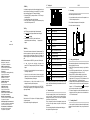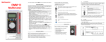
1
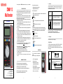
You have just acquired a DMM13 multimeter and we thank you for your confidence. DMM 13 Multimeter User’s manual read these operating instructions carefully; PRECAUTIONS FOR USE This device is compliant with safety standards IEC61010-1 and 61010-2-033 for voltages up to 300V in category III (or 600V in category II) at an altitude below 2,000m, indoors, with a degree of pollution of not more than 2. These safety instructions are intended to ensure the safety of persons and proper operation of the device. If the device is used other than as specified in this data sheet, the protection provided by the device may be impaired. The operator and/or the responsible authority must carefully read and clearly understand the various precautions to be taken in use. If you use this instrument other than as specified, the protection it provides may be compromised, thereby endangering you. Do not use the instrument in an explosive atmosphere or in the presence of flammable gases or fumes. Do not use the instrument on networks of which the voltage or category exceeds those mentioned. Do not exceed the rated maximum voltages between terminals or with respect to earth. Do not use the instrument if it seems to be damaged, incomplete, or poorly closed. Before each use, check the condition of the insulation on the leads, housing, and accessories. Any item of which the insulation is deteriorated (even partially) must be set aside for repair or scrapping. Use leads and accessories rated for voltages and categories at least equal to those of the instrument. If not, an accessory of a lower category reduces the category of the combined multimeter + accessory to that of the accessory. Observe the environmental conditions of use. Do not modify the instrument and do not replace components with "equivalents". Repairs and adjustments must be done by approved qualified personnel. Replace the battery as soon as the symbol appears on the display unit. Disconnect all leads before opening the battery compartment cover. Use personal protective equipment when conditions require. Keep your hands away from the unused test probes of the device. When handling the test probes, crocodile clips, and accessories, keep your fingers behind the physical guard. Disconnect the test probes from the measurement circuit before changing functions. MEASUREMENT CATEGORIES CAT II: Circuits directly connected to the low-voltage installation. Example: power supply to electro-domestic devices and portable tools. CAT III: Power supply circuits in the installation of the building. Example: distribution panel, circuit-breakers, machines or fixed industrial devices. CHAUVIN ARNOUX 190, rue Championnet 75876 PARIS Cedex 18 - FRANCE Tel.: +33 1 44 85 44 85-Fax: +33 1 46 27 73 89 [email protected] Export: Tel.: +33 1 44 85 44 38-Fax: +33 1 46 27 95 59 [email protected] 1.1 For best results from your instrument: CAT IV: Circuits supplying the low-voltage installation of the building. Example: power feeders, counters and protection devices. -1- comply with the precautions for use. The switch The switch has three positions. To access the various functions, set the switch to the corresponding positions. Each active position is confirmed by an audible signal. The functions are described in the table below. Meaning of the symbols used: Risk of danger. The operator agrees to refer to these instructions whenever this danger symbol appears. OFF Stop Battery V/Hz AC or DC voltage measurement/Frequency measurement Automatic detection of the AC or DC voltage to be measured. The CE marking indicates conformity with European directives. Resistance measurement, continuity measurement with buzzer, or diode test and capacitance measurement. Automatic detection of the quantity to be measured. Double insulation or reinforced insulation. Selective sorting of wastes for the recycling of electrical and electronic equipment within the European Union. In conformity with directive WEEE 2002/96/EC: this equipment must not be treated as household waste. DC– Direct current AC– Alternating current AC and DC– Alternating and direct current Earth When switched on, the multimeter is in "SCAN" mode (automatic detection) and analyzes the input signals to determine what quantity is to be measured. In this mode, the "RANGE", "HOLD", and "MAX MIN" keys are deactivated. 1.2 The keypad Here are the functions of the keys of the keypad: - "SEL" (SELECT) key Instructions that must be read and understood 1. PRESENTATION This is an instrument for the measurement of electrical quantities that groups the following functions: The "SEL" key is used to access the functions of the "RANGE", "HOLD", and "MAX MIN" keys and choose the quantity to be measured manually (stops the "SCAN" mode). Press the "SEL" key repeatedly to obtain the following functions according to the setting of the rotary switch: V DC voltage/AC voltage Functions obtained: AC or DC voltage measurement Frequency measurement Resistance measurement/continuity measurement/diode test/capacitance measurement. Functions obtained: Resistance measurement, continuity measurement with buzzer (diode test) Capacitance measurement Automatic determination of the quantity to be measured from the setting of the switch. Test probe: 1 red (+) and 1 black (-). -2- -3- 1.3 - "RANGE" key The display unit 2. USE Your multimeter has a range change function that is normally automatic but can be made manual. After the quantity to be measured is chosen manually ("SEL" key), the default mode is automatic range change: the "AUTO" message is then displayed. Briefly press the "RANGE" key to change to manual mode: the "AUTO" message is then replaced by "MANU". Successive brief presses are used to reach the desired range. Hold the "RANGE" key down for 2 seconds to return to the automatic range change mode: the "MANU" message reverts to "AUTO". 2.1 Commissioning Place the batteries supplied with the device as follows: 1. Using a cross-headed screwdriver, unscrew the screw of the compartment cover on the back of the housing and open the cover. 2. Place the 2 batteries in their compartment, with the correct polarities. 3. Close the cover and screw it back to the housing. "HOLD" key SCAN Automatic search for the quantity to be measured In the "HOLD" mode, the device freezes the display of the last value measured. Pressing the "HOLD" key briefly during a measurement freezes the display: the AUTO Automatic range change MANU Manual range change is then displayed. message A second brief press on the "HOLD" key is used to return to the normal 06 - 2014 694242A02 - Ed. 5 measured value display refresh mode: the message display unit. (Data Hold) Freezes the display Continuity test function disappears from the APO DEUTSCHLAND - Chauvin Arnoux GmbH Straßburger Str. 34 - 77694 Kehl / Rhein Tel.: (07851) 99 26-0 - Fax: (07851) 99 26-60 ESPAÑA - Chauvin Arnoux Ibérica S.A C/ Roger de Flor N° 293, Planta 1- 08025 Barcelona Tel.: 902 20 22 26 - Fax: 934 591 443 ITALIA - Amra SpA Via Sant’Ambrogio, 23/25 - 20050 Bareggia di Macherio (MI) Tel.: 039 245 75 45 - Fax: 039 481 561 ÖSTERREICH - Chauvin Arnoux GmbH Slamastrasse 29 / 2 / 4 - 1230 Wien Tel.: 01 61 61 961-0 - Fax: 01 61 61 961-61 SCANdINAVIA - CA Mätsystem AB Box 4501 - SE 18304 TÄBY Tel.: +46 8 50 52 68 00 - Fax: +46 8 50 52 68 10 SCHWEIZ - Chauvin Arnoux AG Einsiedlerstraße 535 - 8810 Horgen Tel.: 044 727 75 55 - Fax: 044 727 75 56 UNITEd KINGdOM - Chauvin Arnoux Ltd Waldeck House - Waldeck Road - Maidenhead SL6 8BR Tel.: 01628 788 888 - Fax: 01628 628 099 MIddLE EAST - Chauvin Arnoux Middle East P.O. BOX 60-154 - 1241 2020 JAL EL dIB (Beirut) – LEBANON Tel.: (01) 89 04 25 - Fax: (01) 89 04 24 CHINA - Shanghai Pu-Jiang - Enerdis Instruments Co. Ltd 3 F, 3 rd Building - N° 381 Xiang de Road - 200081 SHANGHAI Tel.: +86 21 65 21 51 96 - Fax: +86 21 65 21 61 07 USA - Chauvin Arnoux Inc - d.b.a AEMC Instruments 200 Foxborough Blvd. - Foxborough - MA 02035 Tel.: (508) 698-2115 - Fax: (508) 698-2118 (Auto Power Off) automatic switching off activated Diode test function "MAX MIN" key Display of the maximum and minimum values The device records the maximum and minimum values of the measurements made. The automatic range change does not change the range when this mode is entered; if the maximum values exceed the display range (indicated by the "OL" message), the appropriate higher range must be chosen manually before reactivating the "MAX MIN" mode. Successive brief presses on the "MAX MIN" key produce, in order, the following actions: DC measurement and display AC measurement and display 1st press: the device records and displays the maximum value measured. The "AUTO" message is replaced by "MANU" and the "MAX" message is displayed. "Hz" (Hertz) key When the switch is set to "VHz", a brief press on the "Hz" key displays the frequency of the voltage being measured. A 2nd press restores the display of the voltage being measured. -4- We recommend performing this procedure at the time of commissioning and, if the device is used only occasionally, each time it is used. Hold the "HOLD" key down and switch the instrument on by turning the switch from "OFF" to "Ω". Keep the "HOLD" key pressed and check that the various symbols and segments are correctly displayed (the 1st digit on the left may be a "6" or an "8"). Releasing the "HOLD" key restores the normal display for the function chosen. If the device is set to the resistance measurement function ("Ω"), check that the display indicates "A.P.O" (for auto power off), "SCAN" (for automatic search for the quantity to be measured), dashes "---" (to indicate search in progress). Withdraw the two leads from their compartment and establish a good contact between the metallic parts of the two test probes; the value measured and displayed must (Hertz) unit of frequency (ohm, kilo-ohm, Megohm) unit of resistance V 3rd press: the device records the maximum and minimum values measured simultaneously; it is the value currently measured that is displayed; the "MAX" and "MIN" messages blink simultaneously on the display unit. Press the "MAX MIN" key for two seconds to exit from the mode: the "MANU", "MAX", and "MIN" messages are replaced by "AUTO", indicating that the device once again changes range automatically. 2.2 Display of a negative value Low battery indicator (battery must be replaced) Hz 2nd press: the device records and displays the minimum value measured; the "MAX" message is replaced by "MIN". Additional presses serve to display the values recorded one by one by reproducing the actions of the previous successive presses. Presence of hazardous voltage above 30V (Volt) unit of voltage (milliFarad, nanoFarad, microFarad) units of capacitance The "OL" message (OverLoad) indicates an overshoot of the measurement or display capacity. A display of dashes indicates waiting for the determination and selection of the quantity to be measured. 1.4 The leads and test probes The multimeter is equipped with 2 leads (1 red and 1 black), each terminated by a test probe of the same colour. The leads and test probes are not detachable (they are permanently connected) and, when not in use, can be stowed in the compartments provided for them on the right side of the device. The tips of the test probes (once taken out of their compartments by pressing on them with a finger), allow voltage, resistance, continuity, diode test, and capacitance measurements. The test probes have physical guards that show the operator where the hand grip part ends, beyond which the fingers must not be placed. -5- Starting up and check of operation " (the value displayed change from "---" to "0.0Ω" accompanied by the message " may not be exactly zero, but must remain very close to zero). The instrument is operational when the various states described above have been checked and are correct. The rotary switch can then be set to the desired function or to "OFF" to switch the instrument off. 2.3 Deactivating Auto Power Off In order to extend the life of the batteries, the device switches itself off automatically approximately 10 minutes after it is switched on if no key or change of function has been activated. -6- The device warns that it is about to switch off by emitting 3 series of 2 audible beeps and, if no action is taken, then emits a long beep and switches itself off. When the multimeter has switched itself off automatically, it can be reactivated by any action on a key or on the rotary switch. Automatic switching off can be deactivated by holding down the "Hz", "MAX MIN", or "R-H" key while switching on. To eliminate the slight residual drain of the batteries in the sleep mode, it is always best to switch the device "OFF". 2.4 DC voltage measurement (V ) For optimum safety, measurements of voltages between 300V and 600V must be made only on category III installations or on circuits of which the possible overvoltage levels are known to be less than those of category III. The instrument has 4 measurement ranges: 600mV, 6.0V, 60V, 600V. The 600mV range can be used only in the manual range change mode, by repeated presses on the "RANGE" key. The other ranges can be used in either the manual or the automatic range change mode. Withdraw the test probes and leads from their compartment. Switch the instrument on in the "V" setting. Apply the metallic part of the black test probe on the (assumed) negative part of the circuit to be tested. Apply the metallic part of the red test probe on the (assumed) positive part of the circuit to be tested. Read the measurement result (after stabilization). Display of the "-" sign in front of the numerical value indicates that the value measured is negative (the test probes are reversed with respect to the polarity of the voltage) 2.5 AC voltage measurement (V ) For optimum safety, measurements of voltages between 300V and 600V must be made only on category III installations or on circuits of which the possible overvoltage levels are known to be less than those of category III. The instrument has 4 measurement ranges: 600mV, 6,0V, 60V, 600V. The 600mV range can be used only in the manual range change mode, by repeated presses on the "RANGE" key. The other ranges can be used in either the manual or the automatic range change mode. Withdraw the test probes and leads from their compartment. Switch the instrument on in the "V" setting. Apply the metallic part of the black test probe on the part of the circuit to be tested (assumed) closest to the earth potential. Apply the metallic part of the red test probe on the part of the circuit to be tested (assumed) farthest from the earth potential. In the "SCAN" mode, if the voltage to be measured is greater than 0.5V, the multimeter automatically determines if an AC or DC measurement must be made. If necessary, press the "SEL" key briefly to force an AC voltage measurement (display " symbol instead of " ") of the " Read the measurement result (after stabilization). 2.6 Frequency measurement (Hz) 2.9 For optimum safety, measurements of voltages between 300V and 600V must be made only on category III installations or on circuits of which the possible overvoltage levels are known to be less than those of category III. The instrument has 3 measurement ranges: 600,0Hz, 6,000kHz and 60,00kHz. Measurement of the frequency of the voltage measured: start the AC voltage measurement method, then press the "Hz" key (display of the "Hz" symbol instead of "V"). Read the measurement result after stabilization. 2.7 Resistance measurement (Ω) Resistance, continuity, diode test, and capacitance measurements must be made only on circuits completely disconnected from any power supply, and after any capacitors have been discharged. The instrument has 6 measurement ranges: 600,0Ω, 6,000kΩ, 60,00kΩ, 600,0kΩ, 6,000 MΩ and 60,00 MΩ. All of the ranges can be used with either automatic or manual range change. Withdraw the test probes and leads from their compartment. ". Switch the instrument on and set to " Apply the metallic tips of the test probes to the terminals of the resistance or of the circuit to be tested. In the "SCAN" mode, the multimeter automatically determines the nature of the quantity to be measured. If necessary, press the "SEL" key briefly to change to the desired measurement mode. Read the measurement result (after stabilization). NB: Touching the elements or circuit during the measurement may lead to erroneous results. For resistance measurements on nonlinear circuits, it may be necessary to select the measurement mode and the range to be used manually. Diode measurement (Ω) 3.2 Resistance, continuity, diode test, and capacitance measurements must be made only on circuits completely disconnected from any power supply, and after any capacitors have been discharged. The instrument indicates the voltage across the terminals of the semiconducting junction. " appears. otherwise, press the "SEL" key briefly until the diode test symbol " The test probes must be applied to the terminals of the diode or junction to be tested according to the following polarities. 1) forward direction (conducting): apply the black probe to the cathode and the red probe to the anode. Read the measurement result (after stabilization), see figure A (the threshold voltage of a silicon diode is between 0.5V and 0.7V; it is between 0.2 and 0.3V for a germanium diode. High-voltage diodes, some Zener diodes, and LEDs cannot be tested by this method). 2) reverse direction (non-conducting): apply the black probe to the anode and the red probe to the cathode. Read the measurement result (after stabilization), see figure B (a diode or junction in good condition causes the display of "OL"). With some types of diode, a measured value outside the stated voltage ranges does not necessarily mean that the diode or junction is defective. Relative humidity 45% to 75% Supply voltage 2,8V ±0,3V Frequency range of the applied signal 45-400Hz Sine wave pure Withdraw the test probes and leads from their compartment. Peak factor of the applied AC signal √2 ". Switch the instrument on and set to " Apply the metallic tips of the test probes to the terminals of the resistance or of the circuit to be tested. In the "SCAN" mode, the multimeter can automatically determine and select the continuity mode when the resistance measured remains low; otherwise press AC magnetic field none Electric field none " appears the "SEL" key briefly until the continuity symbol " Read (if necessary) the measurement result (after stabilization). -7- -8- 0.1mV 6.000V 0.001V 60.00V 0.01V 600.0V 0.1V Measurement uncertainties Input resistance 1.0%+3 approx. 10 MΩ AC voltage measurement Range 3.2.3 23°C ±5°C The instrument indicates continuity by emitting a steady sound when the resistance measured is less than 30Ω. The value displayed is the value measured in ohms. Resolution 600.0mV Resolution 600.0mV 0.1mV 6.000V 0.001V 60.00V 0.01V 600.0V 0.1V Measurement uncertainties 45~60Hz 60~400Hz 1.5%+5 - 1.5%+5 Input resistance approx. 10 MΩ General conditions Temperature Resistance, continuity, diode test, and capacitance measurements must be made only on circuits completely disconnected from any power supply and after any capacitors have been discharged. 3.2.2 3. CHARACTERISTICS 3.1 DC voltage measurement Range Switch the instrument on and set to " ". Apply the metallic tips of the test probes to the terminals of the diode or circuit to be tested. In the "SCAN" mode, the multimeter can automatically determine and select the diode test mode when the voltage measured is less than approximately 0.8V, Reference conditions Continuity measurement (Ω) 3.2.1 Withdraw the test probes and leads from their compartment. Quantity of influence 2.8 Characteristics under the conditions of use Sampling rate: approximately 3 measurements per second The uncertainties are expressed in ± (x% L + y digit). -9- Resistance measurement Range Measurement Resolution uncertainties 600.0Ω 0.1Ω 6.000kΩ 0.001kΩ 60.00kΩ 0.01kΩ 600.0kΩ 0.1kΩ 6.000MΩ 0.001MΩ 2.0%+5 60.00MΩ 0.01MΩ 3.0%+5 Voltage maximum applicable 1.0%+5 600V - 10 - 3.2.4 Continuity measurement Range Resolution 600.0 0.1Ω Ω 3.2.5 3.3 Observation No-load voltage The buzzer is actuated at values <≈ 30Ω approx. 0.8V Diode test Range 2.000V Resolution Measurement uncertainties No-load voltage 1.0%+5 approx. 2.0V 0.001V Capacitance measurement Range 3.2.7 Resolution Measurement uncertainties 6.000nF 0.001nF 2.5%+50 60.00nF 0.01nF 2.5%+8 600.0nF 0.1nF 6.000μF 0.001μF 60.00μF 0.01μF Remarks 2.5%+5 600.0μF 0.1μF 6.000mF 0.001mF 3.0%+5 60.00mF 0.01mF 4%+5 - in use in storage Temperature 0°C to +50°C 32°F~122°F -10°C to +60°C 14°F~140°F Relative humidity (RH) ≤80% without condensation ≤70% without condensation Altitude Range Resolution 6.000kHz 0.001kHz 60.00kHz 0.01kHz Measurement uncertainties <2.000m up to 10,000m Rigid polycarbonate shell with moulded elastomer covering Screen LCD display Dimension H 130 x L 81 x P 24mm Weight 150g (without battery) Dimension: L 41 x H 18mm Power supply 2x1.5V (AAA) Mean battery life >250 hours Auto power off delay After approximately 10 minutes without action on the switch and/or on the keys Notes 0.1%+3 Compliance with international standards Electric safety 4.1 The warranty does not apply in the following cases: 1. 2. Cleaning Disconnect the unit completely and turn the rotary switch to OFF. Use a soft cloth, dampened with soapy water. Rinse with a damp cloth and dry rapidly with a dry cloth or forced air. 4.2 If the equipment is sent back to the manufacturer, carriage is paid by the customer. 3. 4. 5. Inappropriate use of the equipment or use with incompatible equipment; Modifications made to the equipment without the explicit permission of the manufacturer’s technical staff; Work done on the device by a person not approved by the manufacturer; Adaptation to a particular application not anticipated in the definition of the equipment or not indicated in the user’s manual; Damage caused by shocks, falls, or floods. 6. DELIVERY CONDITION Replacement of the batteries The symbol indicates that the batteries are spent. When this symbol appears on the display unit, the batteries must be replaced. The measurements and specifications are no longer guaranteed. To replace the batteries, proceed as follows: 1. Disconnect everything connected to the device; 2. Set the switch to OFF; The DMM13 multimeter is delivered in a blister pack with: 2 1.5V batteries a user manual in several languages 3. using a cross-headed screwdriver unscrew the screw of the battery compartment cover on the back of the housing and open the cover; Batteries: 3.6 The instrument has no parts that can be replaced by personnel who are not trained and approved. Any non-approved repair or other work, or replacement of a part by an "equivalent", may severely compromise safety. Dry perfectly before putting back into use. Constructive characteristics Housing 3.5 Frequency measurement 4. MAINTENANCE Environmental conditions 3.4 3.2.6 Environmental conditions Compliant with standards IEC61010-1 and IEC61010-2-033 4. Always replace both batteries; 5. Close the cover and screw it back down. 4.3 Repair Return the instrument to your distributor for any work to be done, whether under the warranty or not. If you have to ship the instrument, it is best to use its original packaging and to state as clearly as possible, in a note attached to the equipment, the reasons for the transfer. 5. WARRANTY 300V CAT III. Sensitivity Range Minimum input signal (sine wave) 10Hz~5.999kHz 6.00kHz~59.99kHz 600mV 60mV - 6.0V 0.3V 3V 60V 2V 6V 600V 20V 60V - 11 - Protection class Class 2, double insulation Electromagnetic compatibility Compliant with standard EN61326-1 Level of protection of the housing Housing: IP40 (according to the standard IEC60529) - 12 - The equipment is warranted against defects of materials or workmanship, in accordance with the general terms of sale. During the warranty period (1 year), the instrument must be repaired only by the manufacturer, who reserves the right to choose between repairing it or replacing it, entirely or partially. - 13 - - 14 -