1
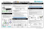
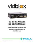
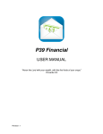
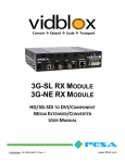
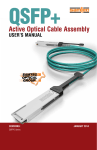
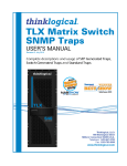
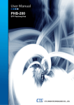
Quick-Start Guide
SL-3G TX MODULE
Step 1
UNPACK VIDBLOX MODULE
Carefully unpack VidBlox module from shipping container and
verify package contents against contents listed below
Step 2
Step 4
GET A CQUAINTED (CONT.)
COMP VGA
DVI
LOCK
SYS
DL
3G
HD
LOCK
USB
POWER
Visually inspect for any signs of damage in shipment or transit
If any components are missing or damaged, contact PESA
Customer Service
PACKAGE CONTENTS:
SMPTE Video
Signal Status
LEDs
Power On
LED
Video Input Signal Status LEDs - Indicate format and lock status of input video entering module
through DVI-I connector from the source as follows:
- Composite (COMP) – composite analog video
- VGA – VGA (RGBHV) analog video
- DVI – DVI digital video
- LOCK – TX module has detected and locked to format of input signal
1
UNPACK
SHIPPING
C ONTAINER
Quick
Start
Guide
Video Input Signal System
Status LEDs
Error
LED
System Error LED - Lights when fault or alarm condition is detected within Vidblox module.
AC POWER ADAPTER –
IF PURCHASED AS
STAND-ALONE
MODULE
USB
Cable
CA TTRAX CUB
INSTALL CD
TECH M ANUAL
CD
2 VERIFY ITEMS SHOWN ABOVE ARE INCLUDED WITH MODULE*
Step 2
GET ACQUAINTED
SMPTE Video Signal Status LEDs - Indicate format and lock status of 3G-SDI digital video signal
leaving module through BNC or fiber connectors as follows:
- DL – Currently not used with Vidblox TX module
- 3G – Digital video signal is SMPTE compliant 3G-SDI (1080p)
- HD – Digital video signal is SMPTE compliant HD-SDI (1080i or 720p)
- LOCK – Output serializers are locked
USB - ”Mini” USB port to connect SL-3G TX module to host PC over standard USB bus
Power On LED - Lights whenever power is applied to Vidblox module
SL-3G TX transmitter module accepts input of DVI or analog video
in SDI broadcast or computer graphic formats at resolution up to
1920X1200
Produces a HD or 3G SDI broadcast quality, SMPTE compliant
output at user-selectable resolutions of 720p, 1080i or 1080p
Analog stereo audio input embedded into SDI output signal
SDI output available at two BNC connectors, and two fiber outputs
through a duplex fiber transmitter device
Modules are Ethernet-ready allowing monitoring and configuration
functions over a network with PESA’s Cattrax control application,
or any single module can be connected to the host PC via a USB
connection using Cattrax Cub controller application
I/O connections to SL-3G TX are shown pictorially below
For further information, refer to Chapter 3 in the Vidblox SL-3G TX User Manual
Step 3
PLACE STAND-A LONE VIDBLOX MODULE OR
INSTALL IN OPTIONAL EXTENDER FRAME
SL-3G TX modules are shipped from factory in “auto-detect” mode for default operating
parameters
In most installations, no further configuration should be required
Locate each module or extender frame for convenient access to video source signals
Ensure primary power is available and that each module or extender frame has clearance for
cooling air
If mounting modules in extender frame, slide module into position from rear, as shown below, and
secure by tightening thumb screw on front of rack panel
Power Distribution/Fan Module
TX
PWR
OUT
1
2
OUT 1
ETHERNET
OUT 2
AUDIO
IN
MONITOR OUT
VIDEO INPUT
Output Formats :
-
720p/50
720p/59.94
720p/60
1080p/50
1080p/59.94
1080p/60
1080i/50
1080i/59.94
1080i/60
Digital Television Output
Transmit module accepts input of DVI-D or analog video through DVI-I connector
Accepts input of unbalanced dual channel analog audio through 3.5mm connector
If desired, a local monitor may be connected to Monitor Out connector
User-selectable output of SMPTE 292M compliant HD-SDI or 424M compliant 3G-SDI
broadcast quality video derived from BNC connectors and SFP fiber transmit channels
Both BNC connectors and SFP fiber transmit channels provide identical SDI outputs - for a
total of up to four separate outputs of SDI video
Network ready and support for DHCP
I/O connections for SL-3G TX transmitter module are shown in following illustration and briefly
introduced in following paragraphs
Using illustration for reference, complete I/O connections to module prior to applying power
SDI Coaxial
Output
TX
Network Port
PWR
OUT
1
2
Power Input
12VDC, 1.5A
OUT 1
SDI Fiber
Output
ETHERNET
OUT 2
AUDIO
IN
MONITOR OUT
VIDEO INPUT
Analog Stereo
Audio Input
(Unbalanced)
Output for Local
Video Monitor
Input for DVI-D or
Analog Computer
Graphics Video
Power (PWR) - Operating power (12 VDC, 1.5A) is attached to this connector. When module is
used standalone, power is derived from a furnished external power supply “brick.” If module is
mounted in rack frame, power is derived from frame power distribution module
Fiber – Dual-channel SFP fiber transmitter device provides identical fiber transport outputs of
SDI video signal which may be distributed to different destinations
BNC Connectors - BNC connectors OUT 1 and OUT 2 provide identical coaxial cable transport
outputs of SDI video signal which may be distributed to different destinations
Audio In – Input jack for unbalanced stereo analog audio signals:
3.5mm Connector Pin
Tip
Ring
Sleeve
Input Audio to Vidblox
Audio Channel 1 - Left Stereo
Audio Channel 2 - Right Stereo
Common Gnd
Embed Channel
Channel 1 of Group 1
Channel 2 of Group 1
Ethernet - Standard RJ-45 connector for connecting Vidblox to a 10/100 Ethernet network
Monitor Out - Provides loop-through output of computer graphics input signal for use by local
monitoring device
Video Input - Connect video input signal to DVI-I connector using cable-end adapters, if
required. Interfacing a source of VGA video to Video Input connector requires use of a VGA-DVI
converter cable. The chart below lists pre-defined input resolutions for use with SL-3G module;
plus up to three custom resolution parameter sets may be defined
External Power
Supply Module A
Vidblox TX Module Scales Source to
SMPTE Compliant SDI Digital Video
Format
CONNECT I/O SIGNALS TO VIDBLOX
DVI-I Video Input Connector
- Digital or Analog Video Input
- Resolutions from 640X480,
up to 1920X1200
DVI-I Looping Output
- Follows Input Signal
Type
Unbalanced Audio
Input Connection
10/100 Ethernet Connectivity
External Power
Supply Module B
(Redundant Power )
When modules are mounted in extender frame, power is derived from external power supply(s)
and connected to individual modules using connector cables from power distribution module
SL-3G TX modules need not be continuously connected to host PC through a network or USB
connection for operation
For further information, refer to Chapter 3 in the Vidblox SL-3G TX User Manual
SL-3G TX – Input Resolutions
576i
576p
480i
480p
720p/50
720p/60
1080i/50
1080i/60
1080p/50
1080p/60
640x480/60
800x600/60
1024x768/60
1280x800/60
1280x1024/60
1360x768/60
1440x900/60
1600x900/60
1680x1050/60
1600x1200/60
1920x1200/60
For further information, refer to Chapter 3 in the Vidblox SL-3G TX User Manual
Computer Source Input
Part No. 81-9059-0668-0 Rev. B
Quick-Start Guide
SL-3G TX MODULE
Step 5
SYSTEM SET-UP AND CONFIGURATION
Set-up, configuration and monitoring functions of Vidblox SL-3G TX module are
performed over a facility network through GUI menu screens of PESA’s Cattrax ®
network controller application installed on a host PC running Microsoft Windows
2000, XP, Vista or Windows 7 operating system; or on a single module through a USB
connection using Cattrax Cub controller application
USB driver file must be installed on host PC in order for Cattrax Cub to communicate
with PESA equipment over USB port
Cattrax and Cattrax Cub automatically search for PESA equipment through a process
called “discovery”
Using Cattrax Cub, only one module may be connected to USB port at a time
Vidblox is shipped from factory with an auto-run CD that loads Cattrax Cub controller
application and USB driver onto a host PC
Communicating with Vidblox over a network:
Locate Cattrax (NOT Cattrax Cub) software CD included with module and place in
drive of host PC
If installation program does not automatically start, navigate to directory of install CD
and double-click Setup.exe
Follow screen prompts to install Cattrax
Ensure that host PC is actively communicating over the facility network
Ensure that an Ethernet cable is attached to the Vidblox network connector
Apply power to Vidblox module by connecting external power supply to module and
to a source of primary power, or connect power cable jumper to Extender Frame
power distribution module
Vidblox supports the DHCP protocol and should automatically receive a valid IP
address from the facility DHCP server, if one is present on the network – if no DHCP
server available, manually enter and select network addressing parameters – see
Chapter 4 of User Manual
Start the Cattrax software control application
If PESA equipment you wish to control resides on multiple subnets, ensure all
required subnets are active – see Chapter 4 of User Manual
Cattrax will discover and display in bold letters the ID of all active Vidblox modules
on the network
Double click the entry for the module you wish to control and proceed to the SL-3G
TX Configuration Screens portion of this guide
Communicating with a single Vidblox module through USB:
Locate Cattrax Cub (NOT Cattrax) software CD included with module and place in
drive of host PC
If installation program does not automatically start, navigate to directory of install CD
and double-click Setup.exe
Follow screen prompts to install Cattrax
When Cattrax Cub has installed, prompt to install USB driver is displayed
Click “OK” to install the driver
If USB driver is not present on host PC, Cattrax Cub will not communicate via USB
with module
Follow screen prompts to install USB driver
Prompt is displayed when driver installation is complete
CONNECT VIDBLOX MODULE TO HOST PC VIA USB PORT:
Ensure that USB driver is installed on host PC
Apply power to Vidblox module by connecting external power supply to module and
to a source of primary power
Step 5
SYSTEM SET-UP AND CONFIGURATION
(CONT.)
CONNECT VIDBLOX MODULE TO HOST PC VIA USB PORT (CONTINUED):
Connect USB cable first to mini-USB
connector on module then to open USB
port on host PC, as shown at right
POWER
Allow “Plug and Play” capability of the SUPPLY
Windows® operating system to interface
Vidblox hardware to host PC
Follow on-screen prompts to complete
hardware installation
Vidblox module should now be
communicating with host PC
Host PC Running
Cattrax Cub
If you encounter any difficulty
with QFX Device Driver
establishing communication with host
Installed
PC, consult the Vidblox SL-3G TX User
Manual
Start the Cattrax Cub software control application
Cattrax will discover and display the ID of the active Vidblox module
Double click the entry for the active module (shown in bold letters) you wish to control
and proceed to the Configuration Screens portion of this guide
For further information, refer to Chapter 4 in the Vidblox SL-3G TX User Manual
SL-3G TX CONFIGURATION SCREENS:
If it is not already started from the previous step, start Cattrax (for network control)
or Cattrax Cub (for USB control)
by clicking desktop icon, or navigating through
Start Menu of the Windows® operating system to Cattrax or Cattrax Cub program
folder and clicking on Cattrax.exe file
Double click the ID of the active (bold letters) Vidblox module you wish to control
Vidblox Information Menu screen similar to that shown below is displayed on PC
monitor
Step 5
INFORMATION MENU
SYSTEM SET-UP AND CONFIGURATION
(CONT.)
STATUS OVERVIEW DISPLAY
Top portion of every menu screen always displays Status Overview data
Module status data updated in real-time:
- Input Resolution – Displays resolution of computer graphics video signal entering
Video Input connector
- Input Type – Displays format of input signal
- Test Mode – Identifies when user-selectable test pattern signal is enabled or
disabled
- Audio Source – Displays embedded audio source as input signal, 1 kHz test tone
or audio muted
INFORMATION MENU
Model and Serial Number – Model identifier and serial number of module
MAC Address – MAC address of module
Type – Indentifies type of module: TX or RX
SW Boot and SW Main – Revision levels of boot code and main program
firmware
FPGA Ver – Indicates version number of code programmed into FPGA device
Alias – Enter any alias name you wish to assign to module
User Text Fields – Use Text Field #1 and #2 to enter information concerning
module
CONTROLS MENU
Input Selection
Video Input Type:
- Auto – Auto is default selection. Vidblox automatically determines format of
incoming video as digital or analog
- DVI – Manually selects incoming video as a digital DVI source
- Analog – Manually selects incoming video as an analog source
Analog I/P Type:
- Auto - Auto is the default selection. Vidblox automatically determines type of
incoming analog video
- VGA - Manually identifies incoming analog video as a VGA (RGBHV) source
- SOG - Manually identifies incoming video as a component analog “sync on green”
signal
- RGBS - Manually identifies incoming video as a RGB component analog signal with
a separate composite sync signal
Input Color:
- RGB – Identifies incoming video as a component analog signal using RGB color
space
- YPbPr – Indentifies incoming video as a component analog signal using YPbPr
color space
Tx Output Control
Aspect Ratio:
- Minimal – Minimal is default selection - Vidblox attempts to process incoming
images without scaling and will only scale images that do not fit into selected
transport stream
- Scale-to-Fit – Scales image to just fit within selected SMPTE transport stream while
maintaining aspect ratio of original image
- Full Screen – Scales input image both horizontally and vertically to completely fill
output transport format – this setting can alter aspect ratio of input signal
SMPTE Format:
- 1080p – Default selection: selects format of SDI transport stream at 1080p
- 1080i – Selects format of SDI transport stream at 1080i
- 720p – Selects format of SDI transport stream at 720p
Field Rate:
- 50Hz – Selects field rate of SDI transport stream at 50Hz
- 59.94Hz – Selects field rate of SDI transport stream at 59.94Hz
- 60Hz – Default selection: selects field rate of SDI transport stream at 60Hz
SL-3G TX CONFIGURATION SCREENS CONTINUED ON NEXT PAGE
Part No. 81-9059-0668-0 Rev. B
Quick-Start Guide
SL-3G TX MODULE
Step 5
S
SYSTEM
YSTEM S
SET
ET-U
-UP
P AND
AND C
CONFIGURATION
ONFIGURATION
(CONT.)
SL-3G TX CONFIGURATION SCREENS
CONTINUED FROM PREVIOUS PAGE
CONTROLS MENU (CONTINUED)
Monitor Output Selection
Loopback Monitor:
- Selects whether local Monitor Out connector is enabled or disabled – default
selection is Enabled
EDID Source
Type:
- Standard – Standard is default selection - reads EDID data from video source signal
- Custom – Allows user to define a custom EDID data stream
- Monitor – Reads EDID data from monitor connected to loop-thru Video Output
connector
Audio
Audio Gain:
- Provides a slider control for gain adjustment of incoming audio from -30dB to +10dB
- default value is zero (0dB)
CONFIGURATIONS MENU
Video Test Pattern Select
Test Mode:
- Enabled – Inserts a user-selectable video test pattern into SDI output signal
- Disabled – Removes test pattern and restores source video to SDI output –
disabled is default selection
Test Pattern:
Clicking arrow opens a listing of available test patterns
Analog Video Adjustments
H position:
Slider control that adjusts horizontal screen position of output display area
V position:
Slider control that adjusts vertical screen position of output display area
Sampling Phase:
Slider control that shifts phase of analog sample - adjust slider for best video quality
DVI Equalizer Settings
DVI Input:
Eight position slider control that selects amount of equalization offered to input
video signal – zero (slider fully left) is minimum and seven (slider fully right) is
maximum
Monitor O/P:
Selects default output level of video signal at Monitor Output connector
- Low – Selects output level of 540mV p-p
- Medium – Selects output level of 770mV p-p
- High – High is default selection – selects output level of 1000mV (1V) p-p
- Max – Selects output level of 1200mV p-p
Audio Source
Audio Source:
- Audio-In – Embedded audio is taken from signal present at Audio In connector on
Vidblox
- 1 kHz Tone – Inserts internally generated 1 kHz tone into embedded output stream
- Mute – Inserts audio silence into embedded output stream
IP Configuration
DHCP On and Off:
- DHCP On is default selection - these buttons toggle dynamic host configuration
protocol (DHCP) function of Vidblox TX module on and off
- When DHCP On is selected, Vidblox automatically receives network IP address
from network DHCP server
- With DHCP Off selected, IP address, Subnet Mask and Gateway parameters
entered in fields below radio buttons are used as network operating parameters
for TX module
- To toggle DHCP mode on or off, click button for desired mode
Step 5
SYSTEM SET-UP AND CONFIGURATION
(CONT.)
CONFIGURATIONS MENU
IP CONFIGURATION (CONTINUED)
- Clicking DHCP Off button activates manual data entry fields below button – in
DHCP On mode, these fields are displayed as inactive
- Click Apply to initiate DHCP mode and IP address change, you will be prompted
to verify this action before process begins
IP Address:
Enter fixed IP address you wish to assign to module
Subnet Mask:
Enter fixed subnet mask you wish to assign to module
Gateway:
Enter fixed gateway parameter you wish to assign to module
Factory Defaults
Factory Reset:
Clicking Factory Reset box restores factory default settings - you will be prompted
to verify request before reset operation is performed
CUSTOM RESOLUTIONS MENU
Select Resolution Number
Select Resolution:
- Click radio button of custom resolution number you wish to configure or verify
- When you select a button the user-defined name and saved parameters are
displayed - if a custom resolution has previously been saved to that resolution
number
- If no custom resolution has been saved, the Name field will be blank and all
parameter fields filled with zeroes
Set Base Resolution
Base Resolutions:
- Clicking arrows opens listing of available base resolutions
- Selecting a base resolution provides a starting point for entering custom resolution
data, based on existing valid resolutions
- Select any resolution listed and data stream parameters for that resolution are
entered in the modifiable Horizontal and Vertical fields
- When entering custom data for a resolution that is a slight deviation from a listed
resolution, Set Base saves you time by filling in modifiable fields with values for
selected reference resolution
- You may modify any or all fields to define custom resolution
- Selecting or starting with a base resolution is not required to enter a custom
resolution configuration
Change Resolution
Name:
- This text field allows you enter a descriptive name to identify custom resolution
being configured
- Click cursor in field box and type desired text
- Press “return” to enter typed data into field
Horizontal:
- Data fields in which you modify or assign data parameter values of horizontal lines
and sync for custom resolution
- When you enter or modify a value in a field, press “return” to actively enter data
- Pixel Frequency field is not modifiable and is shown on screen with a shaded
background - this value is automatically calculated and inserted based on values
entered for horizontal and vertical pixel data
Vertical:
- Data fields in which you modify or assign data parameter values of vertical lines
and sync for custom resolution
- When you enter or modify a value in a field, press “return” to actively enter data
Clear:
- Clicking Clear box clears all entries in all modifiable fields of Change Resolution
grid
- You will be prompted to verify request before Clear operation is performed
Reload:
- Clicking Reload box causes all entries in all modifiable fields of Change Resolution
grid to revert to values currently contained in saved custom resolution
- You will be prompted to verify request before Reload operation is performed
Step 5
SYSTEM SET-UP AND CONFIGURATION
(CONT.)
CUSTOM RESOLUTIONS MENU
Change Resolution (Continued)
Save:
- Clicking Save box writes all entries in all modifiable fields of Change Resolution
grid, plus the user-defined name you entered to internal memory and resolution
look-up table
- You will be prompted to verify request before Save operation is performed
STATUS AND ALARMS MENUS
INPUT VIDEO STATUS MENU
Displays parameters associated with input video signal
FIBER MODULE STATUS MENU
Fiber Module Information
Vendor Name:
- Identifies manufacturer of SFP module
Part No.:
- Identifies manufacturer’s part number of module
Date Code:
- Displays date of SFP module manufacture
Fiber Channel 1 and 2 Status Displays
Type:
- Identifies type of SFP module: TX or RX
TXFault:
- Indicates presence (OK) or absence (Error) of output channel signal
Temperature:
- Analog readout of fiber channel transmitter operating temperature
Power:
- Analog readout in dBm of fiber channel transmitter optical output power
HARDWARE STATUS MENU
Temperature – Fan – Power Status
Board Temperature:
- Analog readout of circuit board surface temperature
Over Temp Threshold Slider:
- Determines temperature (Celsius) at which Over Temp alarm triggers an alert in
Alarms and Events panel – default value is 70° C
FPGA Temperature:
- Analog readout of FPGA device operating temperature
Over Temp Threshold Slider:
- Determines temperature (Celsius) at which Over Temp alarm triggers an alert in
Alarms and Events panel – default value is 70° C
On-Board Fan Status:
- Upper box provides digital readout of FPGA cooling fan speed in RPM, lower box
indicates operating status of cooling fan speed
External Fan Status:
- Provides digital readout of extender frame cooling fan speed in RPM, if module is
mounted in an optional rack chassis – in not rack mounted, reading is zero
Power Board Status:
- Upper box provides digital readout of measured operating voltage of 3.3V power
rail, lower box indicates status of power supply voltage
For further information, refer to Chapter 4 in the Vidblox SL-3G TX User Manual
*If any components are missing or damaged, contact PESA Customer Service by phone
or e-mail.
Customer Service:
Toll Free:
Fax:
Email:
(256) 726-9222
(800) 323-7372
(256) 726-9268
[email protected]
Part No. 81-9059-0668-0 Rev. B