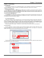
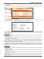
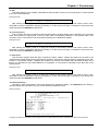
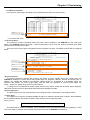
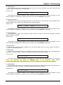
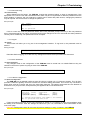
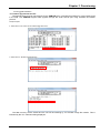
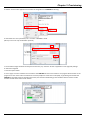
1
 PHB-200
SFP Patching Hub
CTC Union Technologies Co., Ltd. Far Eastern Vienna Technology Center (Neihu Technology Park) 8F, No. 60 Zhouzi St. Neihu District Taipei 114 Taiwan Tel: +886‐2‐26591021 Fax: +886‐2‐27991355 Email: [email protected] [email protected] URL: http://www.ctcu.com PHB‐200 User Manual Fiber Managed Gigabit Ethernet Media Converter Concentrator Rack, 20 channels, 1U Version 1.0 August 16, 2013 (First Release) {This document will be updated when the SNMP option becomes available.} Copyright © 2013, CTC Union Technologies, Inc. All rights reserved. All specifications are subject to change without prior notice.
Legal The information in this publication has been carefully checked and is believed to be entirely accurate at the time of publication. CTC Union Technologies assumes no responsibility, however, for possible errors or omissions, or for any consequences resulting from the use of the information contained herein. CTC Union Technologies reserves the right to make changes in its products or product specifications with the intent to improve function or design at any time and without notice and is not required to update this documentation to reflect such changes. CTC Union Technologies makes no warranty, representation, or guarantee regarding the suitability of its products for any particular purpose, nor does CTC Union assume any liability arising out of the application or use of any product and specifically disclaims any and all liability, including without limitation any consequential or incidental damages. CTC Union products are not designed, intended, or authorized for use in systems or applications intended to support or sustain life, or for any other application in which the failure of the product could create a situation where personal injury or death may occur. Should the Buyer purchase or use a CTC Union product for any such unintended or unauthorized application, the Buyer shall indemnify and hold CTC Union Technologies and its officers, employees, subsidiaries, affiliates, and distributors harmless against all claims, costs, damages, expenses, and reasonable attorney fees arising out of, either directly or indirectly, any claim of personal injury or death that may be associated with such unintended or unauthorized use, even if such claim alleges that CTC Union Technologies was negligent regarding the design or manufacture of said product. TRADEMARKS Microsoft is a registered trademark of Microsoft Corp. HyperTerminal™ is a registered trademark of Hilgraeve Inc. WARNING: This equipment has been tested and found to comply with the limits for a Class A digital device, pursuant to Part 15 of the FCC Rules. These limits are designed to provide reasonable protection against harmful interference when the equipment is operated in a commercial environment. This equipment generates, uses, and can radiate radio frequency energy and if not installed and used in accordance with the instruction manual may cause harmful interference in which case the user will be required to correct the interference at his own expense. NOTICE: (1) The changes or modifications not expressively approved by the party responsible for compliance could void the user's authority to operate the equipment. (2) Shielded interface cables and AC power cord, if any, must be used in order to comply with the emission limits. CISPR PUB.22 Class A COMPLIANCE: This device complies with EMC directive of the European Community and meets or exceeds the following technical standard. EN 55022 ‐ Limits and Methods of Measurement of Radio Interference Characteristics of Information Technology Equipment. This device complies with CISPR Class A. CE NOTICE Marking by the symbol CE indicates compliance of this equipment to the EMC and LVD directives of the European Community. Such marking is indicative that this equipment meets or exceeds the following technical standards: EN 55022:2006, Class A, EN55024:1998+A1:2001+A2:2003, and EN60950‐1:2001 Table of Contents
Chapter 1 Introduction ................................................................................................................................................................. 7 1.0 Introduction ......................................................................................................................................................................... 7 1.1 Functional Description ......................................................................................................................................................... 7 1.2 Chassis Front Description..................................................................................................................................................... 8 1.2.1 LED Indicators ................................................................................................................................................................ 8 1.3 Chassis Rear Description .................................................................................................................................................... 10 1.4 Chassis Physical Dimensions .............................................................................................................................................. 10 1.5 Chassis Specifications......................................................................................................................................................... 11 Chapter 2 Installation ................................................................................................................................................................. 13 2.1 Introduction ...................................................................................................................................................................... 13 2.2 Site Preparation................................................................................................................................................................. 13 2.3 Mechanical Assembly........................................................................................................................................................ 13 2.3.1 Rack mounting............................................................................................................................................................. 13 2.4 Electrical Installation ......................................................................................................................................................... 14 2.5 Alarm Installation .............................................................................................................................................................. 14 Chapter 3. Provisioning................................................................................................................................................................ 15 3.1 Introduction ....................................................................................................................................................................... 15 3.2 Management Methods ...................................................................................................................................................... 15 3.3 Local Console Management ............................................................................................................................................... 15 3.3.1 Terminal Preparation................................................................................................................................................... 15 3.3.2 Console Login............................................................................................................................................................... 16 3.3.3 Main Menu .................................................................................................................................................................. 17 3.3.4 Converter Channel Configuration................................................................................................................................ 17 3.3.5 Device Functions.......................................................................................................................................................... 20 Chapter 4 SNMP .......................................................................................................................................................................... 27 4.1 Introduction ....................................................................................................................................................................... 27 4.1 Telnet Console Management ............................................................................................................................................. 27 4.2 Web based Management................................................................................................................................................... 27 4.2.1 Default IP settings........................................................................................................................................................ 27 4.2.2 Web Manager Operation............................................................................................................................................. 28 Chapter 5 Troubleshooting.......................................................................................................................................................... 30 5.1 Introduction ....................................................................................................................................................................... 30 i Table of Contents
ii Chapter 1 Introduction
Chapter 1 Introduction
1.0 Introduction
Thank you for choosing PHB-200 Gigabit Ethernet Fiber Media Converter Concentrator Rack. If you would like
to skip right to the installation of the Converter Chassis, proceed to Chapters 2.
This manual is used to explain the hardware installation and provisioning procedures for PHB-200, and present
its capabilities and specifications. This manual is divided into 5 Sections, the Introduction, Installation, Provisioning,
SNMP and Troubleshooting chapters.
Installers should carefully read the Chapters 2&3, Installation and Provisioning. The divisions in that manual
are intended for use by personnel to answer questions in general areas. Planners and potential purchasers may
read Chapter 1 Introduction to determine the suitability of the product to its intended use; Operating personnel
would use the Provisioning (Chapter 3) to become familiar with the unit settings. Network Administrators should
read the chapters on Provisioning, SNMP and Troubleshooting (Chapter 3, 4 & 5) to become familiar with the
diagnostic capabilities, network settings and management strategies for the SNMP managed chassis.
1.1 Functional Description
PHB-200 is a 1U high 19" rack mountable device that features 20 completely independent and isolated Gigabit
Ethernet fiber media converters concentrated into a single unit. PHB-200 provides a fixed, high density solution by
placing 20 media converters in one manageable platform. A feature of PHB-200 allows it to detect the working or
failing status either of two power supplies or any fan in the unit and activate relays that can be used to control
external alarm devices.
All settings of the media converters may be managed through any of the available management interfaces. A
local serial COM port allows management from terminal emulation and an easy to use menu system. When the
optional SNMP network management feature is installed, the PHB-200 may be managed via Telnet (menu system),
HTTP GUI or SNMP.
The optical ports of PHB-200 support industry standard SFP modules. Both fast Ethernet and gigabit Ethernet
data rates are supported (100/1000 dual rate). SFP may be typical duplex fiber modules, WDM (BiDi) single fiber
types or CWDM/DWDM types. The PHB-200 supports reading the DOM of any inserted SFP. There is no lock-out
feature, so any third party SFP module may be freely used.
PHB-200 copper twisted pair ports utilized shielded RJ-45 connectors. These Ethernet ports support
10/100/1000M auto negotiation per IEEE802.3u.
PHB-200 may incorporate redundant power supplies. When the unit is ordered with two supplies, they provide
for power redundancy. The supplies, depending on the model, derive power from either an AC power source (100 ~
240VAC) and/or DC power source. Two available DC power options provide either 18-36VDC or 36-60VDC range.
The copper Ethernet and fiber SFP cages are also located on the face, along with status indicator LEDs. The status
LED indicators provide for quick indications of both copper and fiber link statuses and fault detection.
Power &
User I/F Power + control
1 to 20 independent FX to TP media converters
FX TP
PHB200 Simple Block Diagram
7 Chapter 1 Introduction
1.2 Chassis Front Description
The front of PHB-200 has the SFP cages and RJ-45 pairs for each of the independent fiber media converters.
Status LEDs provide real time state of fiber and UTP links. The DB9 female console port is RS-232 DCE for direct
connection to PC COM port with 1:1 cable. This provides an easy to use 'menu system' for local configuring,
operating and monitoring of the PHB-200. No complex CLI (command line interface) must be learned.
20 x 10/100/1000M
Electrical Ethernet Ports 20 x 100/1000M Optical Ethernet Ports Console Port
38400,8,N,1,N Mgmt Port (SNMP) Status
LEDs Figure 1‐1 Chassis Front View 1.2.1 LED Indicators
1.2.1.1 RJ-45 LAN Port
The electrical LAN port of each converter channel has two LED indicators. The left hand side LED is a dual
color LED that indicates the LAN speed on the UTP port. When the LED is off, the speed indicated is 10M
(10Base-T). When the LED is green, the speed indicated is 100M (100Base-TX). When the LED is amber colored,
the speed indicated is 1000M (1000Base-T). The right hand LED is also a dual color LED. When green the LED
indicates a Full Duplex connection and when off, indicates a Half Duplex connection. When this LED is amber, it
indicates the converter is forwarding a link loss (LFP is active).
Speed
Speed 10M 100M 1000M
Duplex/LFP Half Full LFP Duplex / LFP
State OFF GREEN AMBER
Active Flash State OFF GREEN AMBER 1.2.1.2 SFP Cage Fiber LAN Port
The optical LAN port of each converter channel uses an SFP cage. Located directly above each SFP cage are
two LED indicators. The left hand side LED is a dual color LED that indicates the Fiber speed on that port. When
the LED is off, it indicates the port is disabled. When the LED is green, the Fiber speed indicated is 100M
(100Base-FX). When the LED is amber colored, the Fiber speed indicated is 1000M (1000Base-X). The right hand
LED is a green LED that when lit indicates Fiber link state. When off, there is no Fiber link.
SPD SFP LNK
Speed 100M 1000M
Link ACTIVE INACTIVE 1
8 State Active GREEN flash AMBER
State GREEN OFF Chapter 1 Introduction
1.2.1.3 Chassis Status
There are currently 5 functional LEDs in this group with one LED reserved for future use. Below please find a
description for each of these LEDs.
PWR
2
1
SYS
RESV
SNMP
Alarm
LED Color PWR1 GREEN PWR2 GREEN SYS GREEN RESV GREEN SNMP GREEN ALM RED State ON ON
ON OFF
ON OFF
Flash ON OFF
ON OFF
Description Supply is working normally No power, powered off or no supply
Supply is working normally No power, powered off or no supply
The system's CPU is running normally The system is abnormal REnew Software Version, flash during update Blinking once per second, SNMP active No SNMP option is installed The programmable alarm condition is active No alarm or none programmed Note : PWR1 is located on the right hand side of the chassis when viewed from the back of the chassis. PWR2 is located on the left hand side when viewed from the back of the chassis. 1.2.1.4 SNMP Port
This RJ-45 port supports a 10/100M Ethernet connection for management when the optional SNMP module is
installed in the PHB-200. Without the SNMP module, this connector is of no use and connects to nothing internally.
There are two LEDs associated with this RJ-45 connector, a GREEN link indicator for presence or absence of LAN
link and a GREEN activity indicator which will flash whenever there is LAN traffic on this port.
Activity
Link
SNMP
1.2.1.5 CONSOLE Port
This DB9 female connector provides an RS-232 DCE (data communication equipment) asynchronous serial
connection for local management using a simple text based terminal emulator.
CONSOLE
Pin 1 2 3 5 Ref. FG RxD TxD SG Definition Shield to frame ground Receive Data Transmit Data Signal Ground Direction na Out towards DTE In from DTE na 1.2.1.6 Accessory Cable
This DB9F to DB9M cable provides an extension for the RS-232. This cable provides connection between the
PHB-200 and the serial port of terminal.
9 Chapter 1 Introduction
1.3 Chassis Rear Description
The rear panel provides the power input connections (AC+DC chassis shown). Alarm relay contacts are
available via a screw terminal block.
Alarm Relay Contacts Input Power Switch
Terminal Strip
for DC Power Input Power Switch Power Module 2
DC Type Shown IEC AC Mains Input
Cooling Fan
Power Module 1 AC Type Shown Figure 1‐2 Chassis Rear View 1.4 Chassis Physical Dimensions
The following drawing shows the physical dimensions of the PHB-200.
All dimensions are shown in millimeters. Figure 1‐3 Chassis Dimensions, in millimeters 10 Chapter 1 Introduction
1.5 Chassis Specifications
Environment Temperature 0 - 50°C (32-122°F)
Humidity
5-95% non condensing
Alarm relay contact ratings 125VAC
1A
110VDC
0.6A
30VDC
4A
Power Supply Specifications AC Power
Input : Universal, 100~240VAC ±10% (90~264VAC absolute) at ambient temperature
Frequency : 47~63 Hz
Output : DC 12V, 60W maximum rating (Green power rated, 89% power efficiency)
DC Power Module
Input : -36~60 VDC (option 1)
Input : -18~-36VDC (option 2)
Output : DC 12V, 60W maximum rating
Power Consumption 45 watts (max) Heat Generation 154 BTU/hr Compliance European Union : EN55022:2006, Class A, EN55024:1998+A1:2001+A2:2003, and EN60950-1:2001
FCC : part 15, subpart B, class A
Reliability MTTB : >65,000 hours (25°C)
Physical Specifications Dimensions : 438mm (Width) x 302mm (Depth) x 44mm (Height)
(US: 17 1/4" wide x 11 7/8" deep x 1 3/4" high)
Net Weight : 6.7 Kg (US: ~14 3/4 lbs )
11 Chapter 1 Introduction
This page is blank intentionally.
12 Chapter 2 Installation
Chapter 2 Installation
2.1 Introduction
The Installation chapter will cover the physical installation of PHB-200, the electrical connections, interface
connections and cabling requirements. A brief overview of the functional components such as main unit and
management options will also be outlined in this chapter.
Required Tools You will need these tools to install PHB-200:
Number 2 Phillips screwdriver for the 3mm and the 12-24 rack installation screws.
Wrist strap or other personal grounding device to prevent ESD occurrences.
Antistatic mat or antistatic foam to set the equipment on.
2.2 Site Preparation
Install PHB-200 within reach of an easily accessible grounded AC outlet or three wire (-48VDC, Power return,
Earth Ground) central office power. The AC outlet should be capable of furnishing 100 to 240 VAC. Refer to 2.4
Electrical Installation. Allow at least 10cm (4 inch) clearance at the front of PHB-200 for the Fiber and other copper
cables.
2.3 Mechanical Assembly
PHB-200 is designed for rackmount installation and will require 1U space in a standard EIA 19" rack. PHB-200
chassis is delivered completely assembled. The rack mount adapters may be placed along the front or centrally
located on the chassis.
2.3.1 Rack mounting
Bracket may install for 19" mounting. (factory installed) Figure 2‐1 Standard 19" Rackmount Installation of PHB-200 Unit requires 1RU space 13 Chapter 2 Installation
2.4 Electrical Installation
With an AC power supply, AC power is supplied to PHB-200 through a standard IEC C14 3-prong receptacle,
located on the rear of the unit. Any national power cord with IEC C13 line plug may be used to connect AC power
to the power supply. With a DC supply, DC -48V is connected to the terminal block located on the rear of the unit,
observing the proper polarity. PHB-200 should always be grounded through the protective earth lead of the power
cable in AC installations, or via the frame ground connection for DC installations.
IEC C13 line plug Left: Live line
Right: Neutral line
Middle: Ground
-V
DC IN
FG +V
Left: -V (-48V)
Right: +V (0V)
Middle: Frame Ground
36~60VDC
18~36 VDC
Figure 2‐4 IEC (AC) & terminal block (DC) power connector pin assignment 2.5 Alarm Installation
The alarm relay provides one set of Power Failure contacts (normally open and closed) for monitoring the
power and Ethernet link condition of the PHB-200. The alarm contacts may be programmed through the
management interface to react to different fault conditions.
Alarm Relay
Alarm Contact Ratings
125VAC
110VDC
30VDC
NC COM NO
1A
0.6A
4A
Figure 2‐5 Alarm Relay Contacts PHB-200
Programmable alarm relay
Siren, Audible Alarm
DC
Figure 2‐6 Example of electrical circuit for audible alarm 14 Chapter 3 Provisioning
Chapter 3. Provisioning
3.1 Introduction
The information provided here is a detailed description of the management interfaces and methodologies for
managing PHB-200. For details on operation of the SNMP optional feature, please refer to Chapter 4.
3.2 Management Methods
The management method for PHB-200 without SNMP option is limited to a local serial console connection.
When the SNMP option is installed in the PHB-200, management includes IP based textual console (Telnet), web
based GUI management through any standard web browser, SNMP management through proprietary MIB and via
CTC Union's Element Management System (EMS).
3.3 Local Console Management
The PHB-200 has a DB9 female "Console" port located on the front panel, right hand side of the unit. The
RS-232 DCE (data communications equipment) port is designed for a direct 1:1 serial connection to a terminal or
PC COM port and terminal emulation software.
3.3.1 Terminal Preparation
There are a number of common programs which can be used as terminal emulators for Microsoft ® Windows™
based computers. Windows XP® computers already have a terminal emulation program called HyperTerminal™.
However, in operating systems after Windows XP®, such a Windows Vista®, Windows 7®, and Windows 8®, there
is no such terminal emulation program. In these cases, we highly recommend the free emulation program
"TeraTerm Pro". This program can be found freely on the Internet by doing a simple search.
For the remainder of this chapter, "TeraTerm Pro" will be used as our terminal emulator under Windows™.
[TeraTerm Example] Start the application. The 'New connection' pop-up window will appear. Select the 'Serial' radio button. From
the 'Port' pull-down menu, select the communication port. In the example below, the COM port is a USB serial
adapter. After selection of the communications port, click the 'OK' button.
The next step is to configure the serial port communication parameters. To do this, select the 'Setup' pull-down
menu and from that menu, select 'Serial port...'.
15 Chapter 3 Provisioning
The next step is to modify the serial port parameters so that we can establish working communication with the
PHB-200. The communication parameters must be set as follows:
Baud rate: 38400
Data: 8 bit
Parity: none
Stop: 1 bit
Flow control: none
Now, click the 'OK' button and the application will be ready to establish communication with the PHB-200.
Connect the Personal Computer's COM port to the PHB-200's Console port using the provided DB9F to DB9M
cable. Only 3-wire RS-232 is required, pins 2, 3 & 5 (RD, TD and SG). Power on the PHB-200, if not already
powered on. The following login screen will be displayed.
3.3.2 Console Login
The factory default password for the PHB-200 is 'admin'. After successfully logging in, the main status screen
of the PHB-200 will be displayed.
<1>
<2>
<3>
<4>
<5>
<6>
<7>
<8>
<9>
<A>
****************************************
*** CTC UNION TECHNOLOGIES CO.,LTD ***
*** PHB 200 Manager
***
****************************************
Ver:[1.000-1.000-1.000]
Alarm Relay[Enable ]
Link Loss [Loss ]
Power Failure [Loss ]
FAN Failure [Loss
Link Type
[ UTP ][ SFP ]
[ UTP ][ SFP ]
Port 01 Link[ UP
][ UP
]
<B> Port 11 Link[ UP
][ UP
]
Port 02 Link[ UP
][ UP
]
<C> Port 12 Link[ UP
][ UP
]
Port 03 Link[ UP
][ UP
]
<D> Port 13 Link[ UP
][ UP
]
Port 04 Link[ UP
][ UP
]
<E> Port 14 Link[ UP
][ UP
]
Port 05 Link[ UP
][ UP
]
<F> Port 15 Link[ UP
][ UP
]
Port 06 Link[ UP
][ UP
]
<G> Port 16 Link[ UP
][ UP
]
Port 07 Link[ UP
][ UP
]
<H> Port 17 Link[ UP
][ UP
]
Port 08 Link[ UP
][ UP
]
<I> Port 18 Link[ UP
][ UP
]
Port 09 Link[ UP
][ UP
]
<J> Port 19 Link[ UP
][ UP
]
Port 10 Link[ UP
][ UP
]
<K> Port 20 Link[ UP
][ UP
]
<L> Device and Alarm
<P> Password Setup
<Q> Logout
<S> Store Parameters
<T> All Port Configuration
<U> Firmware Upgrade with Xmodem
16 ]
Chapter 3 Provisioning
3.3.3 Main Menu
The main menu is displayed in 5 sections, product header, version, alarm status, per port status and function
group.
Product Header Version Alarm Status Port Status, per port Functions <1>
<2>
<3>
<4>
<5>
<6>
<7>
<8>
<9>
<A>
****************************************
*** CTC UNION TECHNOLOGIES CO.,LTD ***
*** PHB 200 Manager
***
****************************************
Ver:[1.000-1.000-1.000]
Alarm Relay[Enable ]
Link Loss [Loss ]
Power Failure [Loss ]
FAN Failure [Loss
Link Type
[ UTP ][ SFP ]
[ UTP ][ SFP ]
Port 01 Link[ UP
][ UP
]
<B> Port 11 Link[ UP
][ UP
]
Port 02 Link[ UP
][ UP
]
<C> Port 12 Link[ UP
][ UP
]
Port 03 Link[ UP
][ UP
]
<D> Port 13 Link[ UP
][ UP
]
Port 04 Link[ UP
][ UP
]
<E> Port 14 Link[ UP
][ UP
]
Port 05 Link[ UP
][ UP
]
<F> Port 15 Link[ UP
][ UP
]
Port 06 Link[ UP
][ UP
]
<G> Port 16 Link[ UP
][ UP
]
Port 07 Link[ UP
][ UP
]
<H> Port 17 Link[ UP
][ UP
]
Port 08 Link[ UP
][ UP
]
<I> Port 18 Link[ UP
][ UP
]
Port 09 Link[ UP
][ UP
]
<J> Port 19 Link[ UP
][ UP
]
Port 10 Link[ UP
][ UP
]
<K> Port 20 Link[ UP
][ UP
]
<L> Device and Alarm
<P> Password Setup
<Q> Logout
]
<S> Store Parameters
<T> All Port Configuration
<U> Firmware Upgrade with Xmodem
3.3.4 Converter Channel Configuration
To directly manage any of the 20 individual media converters, simply key the port using the numbers 1~9 and
letters a~k. This will take you to the configuration screen just for that specific port.
Ver:[1.000-1.000-1.000]
Alarm Relay[Enable ]
Link Loss [Loss ]
Power Failure [Loss
<< Port 01 Configuration >>
< UTP Information >
UTP Link [ UP
]
UTP Speed [ 1000M ]
UTP Duplex[ Full ]
LFP State [ Normal]
< Port Configuration >
<1>Port Active
[Enable ]
<2>Forward Mode:
[ Store-and-forward
]
<3>Jumbo Frame
[Disable]
]
FAN Failure [Loss
]
< SFP Information >
SFP Link
[ UP
]
SFP Speed
[ 1000M ]
SFP Present [ Exist ]
SFP Tx Fault[ Normal]
<4>Fiber Active
<5>ALS
<6>LFP
<7>Fiber Speed
<D>SFP-DD Information
[Enable ]
[Disable]
[Disable]
[ 1000 ]
< S > Confirm the setting parameters, don't forget to 'store parameters'
<ESC> Go to previous menu. Please select an item.
The individual channel configuration screens will again show the header (not shown here), the version, chassis
alarms, and the current state of the converters UTP Information and SFP Information. Here is a description for each
of these status indications:
UTP Information
UTP Link : An 'UP' status here indicates there is a good link to the UTP port. If there is no link, the status will
be displayed as 'DOWN'.
UTP Speed : This status will be shown as 10M, 100M, or 1000M and it indicates the auto detected speed when
this port is configured for 'auto negotiation'.
UTP Duplex : This status will be shown as Full or Half and it indicates the auto negotiated duplex state when
this port is configured for 'auto negotiation'. If this port is configured for 'auto negotiation' and the connected LAN
device does not support auto negotiation (for example if it is manually set), then auto negotiation will fail and this
port will be placed in Half Duplex mode per IEEE802.3u.
LFP State : The Link Fault Pass through is a mechanism to forward the state of either UTP or Fiber port to the
alternate Fiber or UTP port. This mechanism must be specifically enabled under the option "LFP". When enabled, a
loss of UTP link will force the Fiber link down. Likewise, if the Fiber link experiences link loss, the UTP link will be
forced down.
SFP Information
SFP Link : An 'UP' status here indicates there is a good link to the Fiber port. If there is no link, the status will
be displayed as 'DOWN'.
SFP Speed : This status will be shown as 100M or 1000M and it indicates the manually set speed for the dual
rate (100/1000) fiber port.
SFP Present : This status will either indicate 'Exist' if a compliant SFP module is inserted into the SFP cage or
'None' if there is no SFP present.
SFP Tx Fault : This function is only available in SFP with DDI as described in SFF-8472 Multi-Source
Agreement (MSA). This status will be 'Fault' if Tx Fault is issued from the SFP. When TxFault is cleared, the sttus
will return to 'Normal'.
17 Chapter 3 Provisioning
Port Configuration
<1> Port Active : This converter channel can be completely disabled to block all traffic. When disabled, only the Fiber Speed
LED will be lit and all other LEDs for that port will be off, regardless of the link conditions.
Setting example: ----------------------------------------------------------------------------<0> Disable
<1> Enable
<Esc> Exit
After making the change, press 's' to apply the change in the working memory and make it active. Later,
remember to store the parameter changes by pressing 's' on the main menu page. If changes are not stored, they
will be lost when the PHB-200 is powered off.
<2>Forward Mode : There are two modes for this converter, store & forward (switch) or pass through (converter) modes. The
default mode is store & forward. In this mode the entire packet is buffered in the switch before it is sent out. This
mode must be used when the UTP and Fiber ports are different speed and/or different Duplex. In pass through
mode, the switch is bypassed, allowing the packet to be transparently sent without buffering. However, in pass
through mode the UTP and Fiber speed and Duplex MUST be exactly the same. Pass through mode provides the
lowest latency transmission and also supports any jumbo frame to pass transparently.
Setting example: ----------------------------------------------------------------------------<0> Store-and-forward
<1> Pass through mode
<Esc> Exit
After making the change, press 's' to apply the change in the working memory and make it active. Later,
remember to store the parameter changes by pressing 's' on the main menu page. If changes are not stored, they
will be lost when the PHB-200 is powered off.
<3> Jumbo Frame : According to IEEE802.3, any Ethernet frame larger than 1518 bytes, or larger than 1522 bytes with VLAN tag is
a non-standard frame. Being non-standard, these "jumbo frames" are not compatible with most networks. Currently
the defacto definition for a jumbo frame is one of up to 9600 bytes in size. Most switches, routers, DSL, computers
and WiFi devices do not support these non-standard packet sizes. However, due to marketing pressures, most new
Ethernet chips have support for jumbo frames. If you are on an education network backbone or run a data center,
then you may possibly have use for jumbo frame support. Here, it can be specifically enabled.
Setting example: ----------------------------------------------------------------------------<0> Disable
<1> Enable
<Esc> Exit
After making the change, press 's' to apply the change in the working memory and make it active. Later,
remember to store the parameter changes by pressing 's' on the main menu page. If changes are not stored, they
will be lost when the PHB-200 is powered off.
<4> Fiber Active : This converter channel can completely disable the SFP to block all traffic. When disabled, the Fiber Speed and
Link LEDs will be off and the SFP laser will be turned off.lit and all other LEDs for that port will be off, regardless of
the link conditions.
Setting example: ----------------------------------------------------------------------------<0> Disable
<1> Enable
<Esc> Exit
After making the change, press 's' to apply the change in the working memory and make it active. Later,
remember to store the parameter changes by pressing 's' on the main menu page. If changes are not stored, they
will be lost when the PHB-200 is powered off.
18 Chapter 3 Provisioning
<5> ALS : This safety feature, when enabled, will disable the transmit laser if there is no received signal. It is also referred
to as 'Auto Laser Shutdown'.
Setting example: ---------------------------------------------------------------------------- <0> Disable
<1> Enable
<Esc> Exit
After making the change, press 's' to apply the change in the working memory and make it active. Later,
remember to store the parameter changes by pressing 's' on the main menu page. If changes are not stored, they
will be lost when the PHB-200 is powered off.
<6> Link Transparency : This 'Link Pass-Through' mechanism makes the fiber media converter appear to be 'transparent' for a link state,
either from electrical or optical side. A fault on either side is immediately reflected on the opposite side of the
converter. This LPT mechanism must be enabled manually as it is disabled by default.
Setting example: ---------------------------------------------------------------------------- <0> Disable
<1> Enable
<Esc> Exit
After making the change, press 's' to apply the change in the working memory and make it active. Later,
remember to store the parameter changes by pressing 's' on the main menu page. If changes are not stored, they
will be lost when the PHB-200 is powered off.
<7> Fiber Speed : This converter supports 'dual rate' fiber connection of either 100M or 1000M. This allows the converter to be
used with both Gigabit Ethernet and Fast Ethernet switches. The fiber rate selected must be supported by the SFP
module. In most cases, modern 1.25gbps SFP modules can support both Gigabit and Fast Ethernet rates. Since
there is no 'standard' for fiber speed detection or negotiation, it is important to manually set the fiber rate to the
desired speed.
Setting example: ----------------------------------------------------------------------------<0> 1000M
<1> 100M
<Esc> Exit
After making the change, press 's' to apply the change in the working memory and make it active. Later,
remember to store the parameter changes by pressing 's' on the main menu page. If changes are not stored, they
will be lost when the PHB-200 is powered off.
<D> SFP DD Information : The DDI for SFP is described in SFF-8472 Multi-Source Agreement (MSA). The PHB-200 has the ability to
read and display this information from any vendor SFP that follows SFF-8472.
Display example: ****************************************
*** CTC UNION TECHNOLOGIES CO.,LTD ***
*** PHB 200 Manager
***
****************************************
Ver:[1.000-1.000-1.000]
Alarm Relay[Enable ]
Link Loss [Loss ]
Power Failure [Loss ]
FAN Failure [Loss ]
<< Fiber D/D Function Status >>
Vendor Name
:[CTC UNION
]
Vendor Part Number :[SFS-7020-WA-DD
]
Fiber Type
:[ Single ]
Tx Wave Length
:[ 1310 nm ]
RX Wave Length
:[ 1550 nm ]
Link Length
:[ 0020 Km ]
Tx Power
:[ -05 dBm ]
Rx Power
:[ -07 dBm ]
Rx Sensitivity
:[ -32 dBm ]
Temperature
:[ 48 C
]
<ESC> Go to previous menu. Please select an item.
Tx Power, Rx Power, Rx Sensitivity and Temperature are all extended information available from SFP that support DDI. 19 Chapter 3 Provisioning
3.3.5 Device Functions
From the main menu page, all settings for the PHB-200 device itself can be performed.
<1>
<2>
<3>
<4>
<5>
<6>
<7>
<8>
<9>
<A>
Functions ****************************************
*** CTC UNION TECHNOLOGIES CO.,LTD ***
*** PHB 200 Manager
***
****************************************
Ver:[1.000-1.000-1.000]
Alarm Relay[Enable ]
Link Loss [Loss ]
Power Failure [Loss ]
FAN Failure [Loss
Link Type
[ UTP ][ SFP ]
[ UTP ][ SFP ]
Port 01 Link[ UP
][ UP
]
<B> Port 11 Link[ UP
][ UP
]
Port 02 Link[ UP
][ UP
]
<C> Port 12 Link[ UP
][ UP
]
Port 03 Link[ UP
][ UP
]
<D> Port 13 Link[ UP
][ UP
]
Port 04 Link[ UP
][ UP
]
<E> Port 14 Link[ UP
][ UP
]
Port 05 Link[ UP
][ UP
]
<F> Port 15 Link[ UP
][ UP
]
Port 06 Link[ UP
][ UP
]
<G> Port 16 Link[ UP
][ UP
]
Port 07 Link[ UP
][ UP
]
<H> Port 17 Link[ UP
][ UP
]
Port 08 Link[ UP
][ UP
]
<I> Port 18 Link[ UP
][ UP
]
Port 09 Link[ UP
][ UP
]
<J> Port 19 Link[ UP
][ UP
]
Port 10 Link[ UP
][ UP
]
<K> Port 20 Link[ UP
][ UP
]
<L> Device and Alarm
<P> Password Setup
<Q> Logout
]
<S> Store Parameters
<T> All Port Configuration
<U> Firmware Upgrade with Xmodem
3.3.5.1 Device and Alarm
<L> Device and Alarm : This sub-menu contains information about the power options installed in the PHB-200 and the cooling fan
status. The PHB-200 supports fans with or without tachometer signal. Fans that support monitoring their RPM
(revolutions per minute) are an option.
This menu also has the Alarm Configuration and the System Functions. The details of those will be explained
below.
****************************************
*** CTC UNION TECHNOLOGIES CO.,LTD ***
*** PHB 200 Manager
***
****************************************
Ver:[1.000-1.000-1.000]
Alarm Relay[Enable ]
Link Loss [Loss ]
Power Failure [Loss ]
FAN Failure [Loss ]
<< Device Information and Alarm Configuration >>
< Device Information >
Power Module Info Power Module Type [ Fixed Type
]
Power 1 [ AC Power Module ] [UP ]
Power 2 [ DC Power Module ] [UP ]
FAN Info Detect FAN1 Function [ No FAN RPM function or No FAN ]
Detect FAN2 Function [ No FAN RPM function or No FAN ]
FAN1 RPM [ 0000 RPM ] FAN2 RPM [ 0000 RPM ]
< Alarm Configuration >
Alarm Config & <1> Alarm Relay
[ Enable ] <5> Device Reset
System Functions <2> Link Loss Alarm[ Disable ] <6> Factory Default
<3> Power Failure [ Disable ]
<4> FAN Failure
[ Disable ]
<ESC> Go to previous menu. Please select an item.
<Device Information> The device information includes the inventory and status of power supplies and of the cooling fans. The
PHB-200 is available in 5 power options that include single AC, single DC, dual AC, dual DC and AC plus DC. In
addition, DC supplies are offered in two different voltage ranges, an 18~36VDC or a 36~60VDC range. For
operation with 24VDC, the lower range supply must be used. For operation at normal Central Office DC
power, -48VDC, the higher range option must be ordered.
If cooling fans are installed that support speed sensing, they will be recognized and their speed displayed.
Otherwise, the fans will not be detected and the RPM will be displayed as 0000.
<Alarm Configuration> The alarm relay can be user programmed to act on different faults. A description of the settings follows.
<1> Alarm Relay : This toggle can be used to completely disable the alarm no matter the actual alarm condition. When disabled,
the front panel ALM red LED will be off and the relay will be in the normally open state.
Setting example: ----------------------------------------------------------------------------<0> Disable
<1> Enable
<Esc> Exit
This setting will be applied immediately. Later, remember to store the parameter changes by pressing 's' on the
main menu page. If changes are not stored, they will be lost when the PHB-200 is powered off.
20 Chapter 3 Provisioning
<2> Link Loss Alarm : This toggle can be used to user program the alarm so that it is active in the event of any UTP or Fiber link loss
condition. The Alarm Relay must also be enabled.
Setting example: ----------------------------------------------------------------------------<0> Disable
<1> Enable
<Esc> Exit
This setting will be applied immediately. Later, remember to store the parameter changes by pressing 's' on the
main menu page. If changes are not stored, they will be lost when the PHB-200 is powered off.
<3> Power Failure Alarm : This toggle can be used to user program the alarm so that it is active in the event one of two redundant power
supplies suffers a loss of power. The Alarm Relay must also be enabled.
Setting example: ----------------------------------------------------------------------------<0> Disable
<1> Enable
<Esc> Exit
This setting will be applied immediately. Later, remember to store the parameter changes by pressing 's' on the
main menu page. If changes are not stored, they will be lost when the PHB-200 is powered off.
<4> Fan Failure Alarm : This toggle can be used to user program the alarm so that it is active in the event of fan failure. The Alarm
Relay must also be enabled.
Setting example: ----------------------------------------------------------------------------<0> Disable
<1> Enable
<Esc> Exit
This setting will be applied immediately. Later, remember to store the parameter changes by pressing 's' on the
main menu page. If changes are not stored, they will be lost when the PHB-200 is powered off.
<System Functions> There are two system functions available here; the 'Device Reset' and the 'Factory Default' functions. A
description of the settings follows.
<5> Device Reset : This function can be used to force a soft reboot of CPU and a reset of all the switch chips. The operator must
reply with a 'y' to force a restart. Pressing 'n' or [ESC] will exit this function with no change.
Setting example: ----------------------------------------------------------------------------<Y> Yes <N> No <Esc> Exit
This setting will be applied immediately. Remember, if you have made any other changes, they need to be
saved first. Rebooting will bring the PHB-200 back to the previously saved settings.
CAUTION: Rebooting the unit will block traffic on all channels for about 15 seconds as the unit re-initializes.
<6> Factory Default : This function can be used to return all settings to their original factory default. The operator must reply with a 'y'
to force the default action. Pressing 'n' or [ESC] will exit this function with no change.
Setting example: ----------------------------------------------------------------------------<Y> Yes <N> No <Esc> Exit
This setting will be applied immediately. Later, remember to store the parameter changes by pressing 's' on the
main menu page. If changes are not stored, they will be lost when the PHB-200 is powered off.
21 Chapter 3 Provisioning
3.3.5.2 Password Setup
<P> Password Setup When shipped from the factory, the PHB-200 requires the password 'admin' to login for management. If the
equipment is in a secure room with controlled access, there may be no requirement to reset the password from the
factory default. If, however, the unit is placed in a public area or closet with public access, changing the password
may be required. Use this function to change the password.
Setup example: Old
Password :
New
Password :
Confirm Password :
<ESC> Go to previous menu.
If this is a new unit, enter the password 'admin' at the "old" password prompt. Then key in the new password
twice. If the passwords do not match, the password will not be changed or set. You must enter the same password
correctly twice. Additionally, null passwords are not accepted.
3.3.5.3 Logout
<Q> Logout This function will allow you to log out of the management interface. To log back in, the password must be
entered.
Setting example: ----------------------------------------------------------------------------<Y> Yes <N> No <Esc> Exit
Reminder: Before logging out, make sure any settings that should remain permanent are first stored.
3.3.5.4 Store Parameters
<S> Store Parameters Any changes made to the configuration of the PHB-200 must be saved into non-volatile RAM so they are
restored in the event of power recycling or reset of the PHB-200.
Setup example: ----------------------------------------------------------------------------<Y> Yes <N> No <Esc> Exit
3.3.5.5 All Port Configuration
<T> All Port Configuration The PHB-200 has 20 isolated media converts all built into a single unit 19" rackmount chassis. This "All Port"
provides a method to globally set all 20 converters to the same setting parameters. This can be very convenient if
all the ports need to be active and set to the same fiber data rate. The settings performed here are identical to
those done on a 'per port' basis, except that they are applied to all 20 converters at once.
Setup example: << All Port Configuration >>
<1>Port Active
[Disable]
<4>Fiber Active
[Enable ]
<2>Forward Mode:
<5>ALS
[Disable]
[ Store-and-forward
]
<6>Link Transparency
[Disable]
<3>Jumbo Frame
[Disable]
<7>Fiber Speed
[ 1000 ]
< S > Confirm the setting parameters, please remember to 'Store Parameters'
<ESC> Go to previous menu. Please select an item.
Follow the setting instruction as they were explained in Section 3.3.4. Pressing 'S' here will immediately apply
the setting to all converters. After the settings are tailored for your use, remember to 'Store Parameters' on the
main menu page.
Reminder: Settings done here will over write all previous settings on every converter in the PHB-200.
22 Chapter 3 Provisioning
3.3.5.6 Upgrade Firmware
<U> Firmware Upgrade with Xmodem Occasionally there may be new firmware for the PHB-200 which could add new features or correct bugs found
in the field. The PHB-200 supports field upgrade through the serial console port using Xmodem file transfer
protocol.
Setup example: 1. Select item 'U' to enter the 'Firmware Upgrade' menu. 2. Select item '1' Download Upgrade File. The flash memory will be erased and the unit will be standing by for Xmodem image file transfer. This is
indicated by the 'CC' characters being displayed.
23 Chapter 3 Provisioning
3. Use the TeraTerm Pro application to transfer the image file to the PHB‐200 for writing. 4. Follow the 'File' menu pull‐down, File > Transfer > XMODEM > Send. (Be very sure to use only the Xmodem protocol) a. The firmware image should be located just one directory "up" from the TeraTerm application in the upgrade package. b. Select the image file c. Click the 'Open' button. 5. If all is right, TeraTerm should start to transfer to the PHB‐200 over the serial interface. The progress will be shown on the progress bar. If for some reason transfer does not start (maybe too much time has elapsed), try powering OFF and ON the PHB‐200. As the CPU image has already been erased, the unit will immediately go into Xmodem 'Receive' mode. The file transfer will take about 5 and a half minutes. 24 Chapter 3 Provisioning
6. After the image transfer is completed and the image is written in the device, the PHB‐200 will automatically reboot. The login prompt will again be displayed. Check the firmware version. Version explanation: a.aaa‐b.bbb‐c.ccc where; a.aaa is the H/W (hardware) version, in this example version 1.000 b.bbb is the F/W (firmware) version of the master CPU, in this example version 1.000 c.ccc is the F/W (firmware) version of the 5 slave CPUs, in this example version 1.000 If the slave CPU version shows "?.???", it indicates one or more of the CPU versions mismatch or have checksum error. In this case the upgrade should be run again. 25 Chapter 3 Provisioning
This page was left blank intentionally 26 Chapter 4 SNMP
{At the time of this writing, the SNMP module for this model was still under development. This document will be revised at a later date.} Chapter 4 SNMP
Simple Network Management Protocol (SNMP) is a component of the Internet Protocol Suite as defined by the
Internet Engineering Task Force (IETF). It consists of a set of standards for network management, including an
application layer protocol, a database schema, and a set of data objects.
4.1 Introduction
The PHB-200 has the option of an additional hardware module to provide SNMP management capability. This
module uses an embedded system, interfaces directly with the PHB-200 hardware and provides user interfaces for
Telnet (text menu), Web graphical user interface, and for SNMP protocol using enterprise MIB.
4.1 Telnet Console Management
The Telnet implementation in the PHB-200 with SNMP option provides a remote terminal interface. The
operation of this interface is identical to the local serial console interface but is available remotely via TCP/IP
Ethernet connection. Please refer to Section 3.3.2 for the operation of this text based menu system.
4.2 Web based Management
The SNMP card has 1 10/100 Ethernet port for local/remote management. The IP management provides a
Web based display, with the ability to control all aspects of management in PHB-200.
4.2.1 Default IP settings
The Ethernet RJ-45 port can connect to manager PC by IP.
The default IP settings must follow these communication parameters: IP address: tbd Subnet mask 255.255.255.0 Default Gateway (don't care) Username: admin Password: admin 27 Chapter 4 SNMP
4.2.2 Web Manager Operation
PHB-200 with SNMP supports web based management. Use your favorite browser (Chrome, Firefox, Internet
Explorer or Safari) and connect to PHB-200 by using the SNMP's IP address.
28 Chapter 4 SNMP
29 Chapter 5 Troubleshooting
Chapter 5 Troubleshooting
5.1 Introduction
{This chapter will be added in a later revision of the document.} 30 Chapter 5 Troubleshooting
31