1
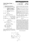
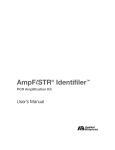
l l l l l l l l l l l Il l l l l l l l l l l l l l l l l l l l l l l l l l
US005172311A
United States Patent [191
[111
[45]
Reinhart et al.
[54] ELECTRICAL AMPLIFIER FOR
[75] Inventors: Peter Reinhart, Lohr/Main; Karl
Hessdiirfer, Karlstadt; Horst Lausch,
Lohr/Rodenbach, all of Fed. Rep. of
Germany
Mannesmann Rexroth GmbH, Fed.
Rep. of Germany
[21] Appl. No.: 865,623
[22]
Filed:
5,172,311
Dec.‘ 15, 1992
Date of Patent:
FOREIGN PATENT DOCUMENTS
CONTROLLING VALVES
[73] Assignee:
Patent Number:
, Apr. 8, 1992
0094090 1 l/1983 European Pat. Off. .
0149010 7/1985 European Pat. Off. .
10/1984 Fed. Rep. of Germany .
6/1985
9/1985
12/1985
3/1986
7/1987
7/1988
7/1988
Fed.
Fed.
Fed.
Fed.
Fed.
Fed.
Fed.
3/ 1989 Fed.
5/1990 Fed.
Rep.
Rep.
Rep.
Rep.
Rep.
Rep.
Rep.
Rep.
Rep.
of Germany
of Germany
of Germany
of Germany
of Germany
of Germany
of Germany
of Germany
of Germany
.
.
.
.
.
.
.
.
.
OTHER PUBLICATIONS
Related US. Application Data
[63]
Digitale CNC-Streckensteuerung, Mar. 1987.
Continuation of Ser. No. 434,370, Nov. 13, 1989, aban
doned.
[30]
Foreign Application Priority Data
Nov. 11, 1988 [DE]
“One-Axis and Two-Axis Controller User’s Manual,”
including Appendices A, B, C and D, Index and Supple
ment (Appendices E and F), Feb. 1987.
(List continued on next page.)
Fed. Rep, of Germany ..... .. 3838353
Primary Examiner-Jerry Smith
[51]
Int. Cl.5 ............................................ .. G06F 15/4-6
Assistant Examiner——Paul Gordon
[52]
US. Cl.
Attorney, Agent, or Firm--Harness, Dickey & Pierce
[58]
Field of Search ................. .. 364/167.01, 140, 141,
.............
. . . ..
364/140; 364/l67.0l
364/142, 188, 189, 509, 510; l37/624.ll,
624.18, 624.2
[56]
[57]
ABSTRACT
Ampli?er units for controlling valves, in particular
proportional solenoid valves, comprise a number of
References Cited
components such as an end stage, a power supply, a
U.S. PATENT DOCUMENTS
control electronics and possibly a closed loop control
4,134,423
4,523,286
l/l979
6/1985
4,573,114 2/1986 Ferguson et al.
4,595,979
6/1986
Arai et al. ......... ..
4,627,009 l2/l986 Holmes et al. ..
4,628,442
12/1986
including signal inputs for desired and actual values.
Mayer ....................... ..
Koga et al. .... ..
Isobe et al.
.. .. ..
137/486
137/551
364/l67.01
364/167.01
364/167.01
. . . . . . . ..
364/200
4,628,444 12/1986 Nozawa et a1, .
364/1670]
4,722,044 l/l988 Heiser et al.
4,744,022 5/1988 Kumar et al.
364/167.0l
364/l67.01
The control electronics generates a desired positioning
characteristic for each type of valve. According to the
invention, the control electronics is replaced by a pro
grammable component including a read-only-memory
in which the ampli?er is associated to a particular type
of valve by loading the read-only-memory with valve
speci?c data which specify a particular type of valve.
The invention allows to manufacture and to stock non
4,744,218
5/1988
Edwards et al.
..... .. 60/368
programmed ampli?ers of identical structure. To make
4,745,744
5/ 1988
Cherry et al. . . . . . . .
. . . .. 364/167
an ampli?er unit ready for use a particular program is
loaded to suit the ampli?er to the valve type.
4,754,392 6/1988 Nakashima et al.
364/l67.0l
4,755,729
364/l67.01
7/1988
Gotou ........... ..
4,790,233 12/1988 Backe et a1. .
364/l67.01
4,816,987 3/1989 Brooks et al.
364/167.01
4,879,644 11/1989
4,979,127 12/1990
Gottshall ....... ..
364/l67.0l
Mizuno et al. ............... .. 364/l67.0l
idngpivtlai
ntemol
desired values
Multipexr
15 Claims, 3 Drawing Sheets
5,172,311
Page 2
OTHER PUBLICATIONS
Blickley, George J., “Servo Becomes Digital Actua
tor,” Control Engineering, Jun. 1986.
“Elektronik-Lexikon”, 1974, pp. 206, 84-86.
“XPERT” Linear Actuator (XLA) User Manual, Jul.
“Digitale Reglerkarte-Mikrorechner”, Oct. 1986.
1986.
Catalog, Mannesrnann Rexroth RD 29943/ 1.86 pp.
306(1)-3l3(7), Jan. 1986.
Catalog, Mannesmann Rexroth RD 29985/ 10.85 pp.
342(6)-345(3), Oct. 1985.
M006 Datenblatt D 243.01.01, Sep. 1986.
Dip1.-Ing. Dieter Scholz, Aachen, “Korrektur von
Ventilkennlinien mit Hilfe von Mikorprozessoren,”
1986, pp. 209-233.
DE-Prospekt Digitaregler DR 10, Gesellschaft ?ir
Antriebs-unde Steuerungstechnik mgH and Co. KG,
D-7742 St. Georgen/Schwarzwald, Jul. 1985.
Prof. Dr.-Ing. W. D. Goedecke, Dr. —Ing. R.
Schwenzer, DE-Z: Fluid, Apr. 1985, “Wenn die A11
tags-Pneurnatik nicht reicht”.
Dipl.-Ing. Dieter Scholz, Aachen, “Korrektur von
Schreiben des VDMA an die Mitarbeiter des AK 13
Hoonhorst, Hans, “Bendix Sequential Fuel Injection,”
Bendix Electronics, 1986.
Dubbel, Taschenbuch ?ir den Maschinenbau, 1981, p.
1085.
DE-Z: NN: “Impulse ?ir Servo”, ?uid, Apr. 1987, pp.
24-26.
Ventilkennlinien mit I-Iilfe von Mikroprozessoren,” 7.
DE-Bosch Hydraulik,
Aachener Fluidtechnisches Kolloquium, Mar. 1986.
Verf. H. Rummel, “Baggertechnik am Beispiel des RH
90,” Oct. 1987.
Auf der 21 Bauma verteilter Prospekt der Firma O and
K, Aufbruch In Neue Leistungs-Dimensionen.
Zeichnungen zur Darstellung eines Pumpen-Managin
Regelungstechnik, S. 57.
DE-Z: 8. Aachener Fluidtechnisches Kolloquium, S.
g-Systems, angefertigt durch die Einsprechende Dec.
1983.
Prior use 1983 by Lothar I-I. Pees “Propcon 10” (Valve
1987; Elektrohydraulische
303-321, Dr. Feuser.
.DE-Zz8. Aachener Fluidtechnisches Kolloquium, Mar.
115, 1988, S. 323-340, Mauer et a1.
DE-Z: Scholz, D.: Ventilansteuerung und-regelung
mit digltaler Signalverabeitung. In: o+p olhy-draulik
und pneumatik 29, (1985) N0. 1, S. 21-24.
ampli?er) May 1984.
“System 90 Microcontroller”, Sundstrand-Sauer, Apr.
DE-Z: Burkel, R., Romes, R.: Integration von Elek
tronik in Bauelemente der hydraulischen Antriebstech
nik. In: o+p olhydraulik und pneumatik 32, (1988), No.
1987.
4, S. 231, 232, 234, 236, 239, 240, 242, 244, 246.
Fisher, C.: Systeme der elektrohydraulischen Antrieb
s-und Steuerungstechnik; o+p “Olhydraulik und
pneumatik” 31, (1987), No. 4, pp. 354, 357, 358.
479-484.
VDI-Berichte vom Sep. 1988, pp. 176, 177, 136.
DE-Z: Anders, P.: Symbiose Mikroelektronik/Fluid
Pelka “Was ist ein Mikroprozessor”, Franzis-Verlag
1981, pp. 8, 9, 16,17.
Siemens Components 24 (1986) Heft 2, p. 63.
technik. In: o+p olhydraulik und pneumatik 32, (1988),
Prior use 1987 by Ottmar Knisch “CPS 1O und CPS
20", Aug. 1987.
'
“Kraftfahr Technisches Taschenbuch”, 1987, pp. 63,
130, 131.
DE-Z: Backe, W.: Fluidtechnik im Wandel. In o+p
olhydraulik und pneumatik 32, (1988) N0. 7, S. 473-476,
No. 7, S. 487-492, 494, 497-499.
DE-Z: Burkel, R.: Symbiose Mikroelektronik/
Fluid-technik. In: o+p olhydraulik und pneumatik 32,
1988, No. 7, S. 500-506.
Sloan et al., IBM Technical Disclosure Bulletin, v01. 21,
N0. 3, Aug. 1978.
US. Patent
Dec‘. 15, 1992
Sheet 1 of 3
.a
3% 8c
6382?
2g
@
s2>a 8
isg
5,172,311
US. Patent
I Dec. 15, 1992
Sheet 2 0:3
5,172,311
1
5,172,311
ELECTRICAL AMPLIFIER FOR CONTROLLING
VALVES
2
ample for indicating a broken cable may be helpful. As
mentioned before, the ampli?er may be a closed loop
ampli?er so that additional inputs are provided for the
feed-back of actual values such as the solenoid current
This is a continuation of US. patent application Ser. 5 and/or the valve piston position or pressures occuring
at the valve or adjusted by the valve. Still further the
No. 07/434,370, ?led Nov. 13, 1989 and now aban
doned.
endstage is controlled by a pulse width modulated sig
nal thus supplying a pulsed current having a ?xed or
The invention relates to electrical ampli?ers for con
trolling ?uid power valves, comprising a supporting
structure associated to a valve. The supporting struc
ture includes at least an end stage, a power supply, a
freely selected frequency to the valve solenoid. The
forgoing enumeration of individual components of a
valve ampli?er should not be considered to be com
control electronics for generating valve speci?c posi
plete. Further details are found in the handbooks of
tioning signals to obtain a predetermined control or
output characteristic of said valve. The supporting
valve manufacturers, for example in MANNESMANN
REXROTH RD 29003/ 3.88 “Hydraulic and electronic
structure also includes inputs for delivering desired
value signals to the control electronics and outputs
components for proportional and servo-systems”.
connected to the endstage. The control electronics or,
respectively the supporting structure may be supple
The ampli?er components are regularly mounted on
a supporting plate which in turn may be mounted to suit
mented by a number of components, i.e. at least a con
a speci?c purpose. Simple circuit ampli?ers having a
limited number of terminals and lacking setting means
troller including inputs for at least an actual value, a
such as desired value setters may be mounted in a casing
ramp generating unit top modulate desired values, in
puts for activating desired values, and outputs to a dis
play and to circuits for failure recognition.
which is called a module. More sophisticated ampli?ers
which include means for setting valve speci?c and am
pli?ers speci?c parameters such as desired values, ramp
BACKGROUND OF THE INVENTION
Conventional ampli?ers and closed loop control am
pli?ers to drive valves, in particular proportional sole
noid valves are made up of a number of individual com
ponents. Thus the current through the solenoid wind
ings is controlled by an endstage to which power is
supplied by a suitable power supply. The ampli?er fur
ther receives signals de?ning a number of desired values
such as valve piston positions, ?uid flow volumes and
pressures. Additionally desired values are set by poten
tiometers and will be supplied to the ampli?er by oper
times etc. are mounted on a supporting plate including
25 a front plate to accomodate switches, push buttons or
display elements. A number of ampli?ers of this type are
combined in magazines. Modules and magazines are
assembled in a switching board. Otherwise it is possible
to mount an ampli?er directly to a valve adjacent the
valve casing or to secure it to a valve sandwich plate.
A substantial disadvantage of the prior art valve am
pli?ers is the need for a great variety of individual am
pli?ers to serve the various types of valves and valve
sizes to be held on stock so that a particular ampli?er
which is associated' to a particular valve is available.
ating switches. Desired values for the piston position of
According to the prior art the individual valve types
and valve sizes further need speci?c ampli?ers in a
the valve or the height of the pressure for example are
variety of embodiments. For example one embodiment
generated in an analogue manner. A main component of
for each valve integrated assembly, the modul assembly
each ampli?er is the control electronics which is con
nected between the desired value input and the endstage 40 or the magazine assembly must be stocked. All the vari
ous ampli?er types must be separately manufactured
and which generates the positioning signals for the
and held-on stock.
control and output characteristics of the valve in accor
dance with a valve speci?c program. This program will
SUMMARY OF THE INVENTION
vary in response to the function of the valve and the
It is an object of the present invention to avoid the
valve size. As an example such control may be em
multiplicity of ampli?er types referred to above and to
ployed in directly operated or pilot operated directional
simplify the manufacturing process as well as stocking.
proportional valves operating with and without feed
The present invention provides an ampli?er which
back, directly operated or pilot operated pressure
overcomes many of the problems associated with the
valves, pressure limiting valves or pressure reducing
ampli?er types previously known.
valves, further flow valves, directional servo-valves or
According to a main feature of the present invention
servo-pressure-valves. Such control ampli?er may 0p
a control electronics is de?ned by a programmable unit.
erate a variety of valves having a predetermined func
tion which requires a certain algorithm for generating
positioning signals in the ampli?er to obtain a predeter
The programmable unit is programmed to perform all
functions necessary for each valve type to generate a
mined interrelationship between setting a desired value 55 particular positioning signal. The unit is connected to a
read-only-memory into which the variable and constant
and generating a suitable output current in the endstage.
values of the individual valve type and the control pro
In addition, the size of the valve and thus the stroke and
gram for this valve are loaded. Each ampli?erv thus
the geometry of the valve piston must be considered to
comprises an endstage, a power supply suitable for the
obtain the proper signal.
These requirements result in control electronics and 60 associated valve and the programmable unit including
an interface and a read-only-memory in which the valve
ampli?ers are valve speci?c. This means that each valve
and ampli?er speci?c data and programs are stored.
type or at least each valve family needs an individual
speci?cally designed ampli?er.
All these data are de?ned to determine the function
of the valve, its size and even the manufacturing toler
Moreover the control electronics may include further
components all known to the artisan. For example to 65 ances as well as different control types and different
obtain a continuous transient of response from a sudden
variation of a desired value a ramp circuit may be use
ful. Components for the recognition of failure, for ex
control gains.
Furthermore the general operational program for the
data processing of the programmable unit is stored in
5,172,311
3
.
the read-only-memory. These data stored are preferably
variable so that input-terminals are provided, in particu
lar for digital values to vary the values desired. This
may be performed by means of a keyboard. The data
may further be fed to a display. This is of particular
advantage when initially loaded data are manually var
ied to optimize the valve characteristic, which varied
4
front plate for accomodation of the key-board and the
display elements. According to the invention a particu
lar ampli?er plate is associated to a particular valve
type. To facilitate this association, a valve code is pro
vided. This means that the ampli?er plate receives a
valve code in which the associated valve type is binary
coded when the ampli?er unit is associated to a particu
data are then transferred via the interface to a master
lar valve. This may be checked by reading out the valve
processor where the data are stored to be ready for
delivery. This is of use when further valves of the same
type are to be programmed. According to this embodi
ment of the invention there is provided a bidirectional
code to make sure that the memory is loaded with the
data transfer.
-
valve speci?c data only or, respectively, to make sure
that the end stage may be activated only when the
proper valve code associated thereto is presented.
Reading out is performed when the initializing routine
is performed i.e. when the initial stage of the ampli?er is
In a still further embodiment, the endstage may be
located on a supporting structure together with the 15 reset.
power supply to which supporting member the pro
BRIEF DESCRIPTION OF THE DRAWING
grammable unit including the read-only-memory on a
FIG. 1 is a perspective view of an ampli?er unit de
so-called daughterplate is soldered or pinned. This
signed for mounting on a valve or valve sandwich plate
daughterplate is identical for all types of valves. Merely
the endstages need a few different embodiments since 20 for controlling a proportional solenoid valve,
FIG. 2 is a perspective view of an ampli?er unit in
different output-currents are necessary in accordance
cluding a front plate (Eurocard system) for controlling
with the valve size. However, the invention provides
a valve and
for a substantial simpli?cation in stockholding and man
FIG. 3 is a block diagram of an ampli?er unit
ufacturing by using a programmable unit and read-only
memory in combination with the non-programmable 25
DETAILED DESCRIPTION
components such as the endstage and the power stage.
Referring now in detail to the drawings, FIG. 1 illus
Accordingly the ampli?er may be manufactured re
trates an ampli?er mounted on a supporting plate 2 for
gardless of the individual valve types to be controlled.
connection to a valve 1. The supporting plate 2 carries
Ampli?er carrying plates are manufactured which are
an endstage 4 and a power supply 5. A daughter plate 3
identical to each other and are different in the endstage
for accomodating a programmable unit 6 and a read
only. As a rule, a variety of two or three different ends
only-memory 7 is mounted on the supporting plate 2.
tages will be suf?cient so that manufacturing and stock
Still further the supporting plate 2 comprises a num
are greatly simpli?ed. To suit an ampli?er for a particu
ber of terminals for transmitting and/or receiving sig
lar type of valve the ampli?er is connected via the inter
face to an external processor from which the complete 35 nals such as positioning output values, actual values,
data exchange with an external computer and terminals
program and data, such as the ampli?er and valve spe
for connecting the power supply unit 5 to a line voltage
ci?c data and the program are loaded to the program
and for electrical connection of the valve 1.
mable unit and in the read-only-memory. Then the am
Similar basic supporting plates are provided for all
pli?er is programmed for a particular valve type and
types of valves. They distinguish from each other sub
size.
stantially by different endstages 4 only. By limiting the
Further claims relate to particularly useful embodi
design to a few embodyments, for example incorporat
ments of the invention. For example the interface al
ing endstages with two different output current values,
lows for a bidirectional data transfer between the ampli
the stock required comprises a few different basic units.
?er and an external processor. Accordingly the ampli
?er may be incorporated in a central control in a plant. 45 In FIG. 1 the ampli?er controls a directly actuated
directional proportional solenoid valve of a predeter
Further, the external computer may use data received
mined rated size. The program required for control is
from the ampli?er to optimize the process.
transmitted from a computer via the interface to the
The programmable unit further includes digital and
ROM 7 by means of the programmable circuit 6. Ac
analogue inputs. The analogue inputs for desired values,
actual values as feed-back of pressures, valve piston 50 cordingly the ampli?er for the valve 1 is programmed
and ready for operation after being tested for the hard
positions and/or current values in the solenoid windings
are supplied through an internal multiplexer to an analo
ware valve characteristic.
FIG. 2 illustrates an embodiment of an ampli?er unit
gue/digital converter. Digital inputs allow read out of
including a keyboard and display for calling up and
desired values stored and further allow performance of
additional functions, for example to vary stored param 55 changing data and for displaying data. This can take
place interactively without standstill of the ampli?er.
eters and to vary desired values by actuating a keyboard
For changing the, the ampli?er can be programmed
connected thereto.
using the keyboard 9 and the display 10. The keyboard
These additional functions determine the embodi
further allows to change data in the memory. As shown
ment of the ampli?er structure. When a subsequent
setting is not necessary for example with an ampli?er 60 in FIG. 2, the keyboard 9 and the display 10 are dis
posed on a front plate of the unit.
incorporated in a valve or valve sandwich plate, the
ampli?er is easily mounted in a casing including a few
FIG. 3 illustrates the components of the ampli?er.
terminals. When additional input terminals are needed
The programmable component comprises a multiplexer
to perform externally controlled functions of the valve,
the ampli?er unit may be mounted in a module casing.
11 to which analogue data are applied which are cycli
cally scanned in the multiplexer 11 and are transferred
When still further input terminals are desired such as a
via an analogue/digital converter 12 to a data bus 15.
keyboard and a display allowing to vary and display
certain values, the supporting plate is provided with a
Additionally a number of digital inputs 16 is provided to
the data bus 15. The programmable component further
5
5,172,311
6
comprises a microprocessor 17 to perform arithmetic
to be controlled, said supporting structure including at
calculations, a random excess memory 18 and an inter
least an endstage, a power supply, a control electronics
face 13 for a series transfer of data from and to the
for generating valve speci?c positioning signals to ob
tain a predetermined operation of said valve, and inputs
computer 14. The data transmitted through the inter
face 13 to program the ampli?er are stored in a random
memory 7.
for delivering desired valve parameter value signals to
well as the signals de?ning the actual values are sup
plied to the programmable unit 6 in which the corre
said control electronics and outputs connected to said
endstage, characterized in that said control electronics
comprises a read-only-memory and a programmable
unit including at least a microprocessor, a working
lated signals for controlling the endstage are read from
the memory 7 and processed. The digital output signal
memory, analog and digital inputs and outputs includ
ing signal convertors, means for loading said read-only
is converted by the digital/analogue unit 19 to an ana
memory with a program of operation, a valve speci?c
program, and a plurality of associated data from said
programmable unit and said microprocessor via an in
In operation the signals de?ning any desired values as
logue control signal for the endstage 4. The voltage
supply of the electronics and of ‘the endstage is provided
by the power unit 5. The control may be performed by
an external master processor to which the data gener
ated by the ampli?er are supplied to optimize the pro
cessing control.
The multiplexer 11 is electrically connected to a num
ber of analogue transducers, in particular for receiving
terface, wherein said supporting structure further com
prises a valve code storing means which provides a
binary code for a particular type of valve, said code
being read out in performing a checking-mode, and
wherein said programmable unit includes a number of
digital inputs for loading said valve code in order to
compare the valve speci?c program with the valve
measuring signals of a variety of actual values such as 20
pressures, valve piston positions and/or solenoid cur
code stored in the valve code storing means when per
rents as well as an external ramp time modulator. The
forming the checking-mode.
ampli?er unit is further connected to an analogue de
2. The ampli?er of claim 1, wherein the data stored is
sired value setter through the multiplexer 11.
varied via digital inputs of the programmable unit.
Now turning to the digital input 16 there is a variety 25 3. The ampli?er of claim 1, wherein the program of
of functions. For example any signals de?ning desired
operation, the valve speci?c program and the associated
values stored in the ROM 7 may be activated by the
input “calling desired values”. A total of 15 desired
values may be read from the memory in using 4 keys
provided the desired value reading is coded corre
spondingly. Each desired value is associated with at
least a predetermined ramp time during which the de
sired value changes. The associated ramp times are
data can be transferred in either direction via said inter
stored a like in the memory.
ble component includes at least an input to activate
A further input “ramp out” allows maximization of
the ramp time so that the desired value is delivered as a
positioning value having a minimum delay which is
face.
4. The ampli?er of claim 1, wherein adjustable de
sired value signals for the valve and operational param
eters are loaded to and read out from the read-only
memory.
5. The ampli?er of claim 1 wherein said programma
reading out and varying the desired value signals stored
in the read-only-memory.
6. The ampli?er of claim 1, wherein said programma~
inherent to the system.
ble unit includes at least an input to receive an signal in
The inputs “start-stop operation” allow control of the
case of a failure to reset the positioning signal for the
valve by means of push-button switches which are lo
valve in a predetermined stage by means of the pro
cated at different places of the plant to continuously 40 gram.
adjust the valve towards opening or closing.
Provided the plant comprises a number of identical
valves and associated ampli?ers, the inputs “valve ad
dress” allows to select the valve to be actuated pro
7. The ampli?er of claim 1, wherein said programma
ble unit includes at least a pair of inputs for a start-stop
operation to continuously vary the positioning signal
for the valve.
‘
vided the input receives a signal, whereas the desired 45
8. The ampli?er of claim 1, wherein said programma
values for the other valves are not change thereby.
ble unit includes inputs for a keyboard.
The high concentration of processing data in the
9. The ampli?er of claim 1, wherein said programma
amplifying unit makes it possible to recognize and to
ble unit includes a multiplexer for analogue signal inputs
display errors in response to data processing to improve
of desired values and actual values.
the safe processing of the positioning value. The error is
10. The ampli?er of claim 1, wherein said valve is
indicated through a further digital input “error indica
controlled via said interface from an external processor.
tion”. After processing the error signal or, respectively
11. The ampli?er of claim 1, wherein the data stored
eliminating the error, the ampli?er provides an “en
in the read-only-memory are read out via said interface
abling signal” to reinitiate the control of the valve.
and wherein said data are varied.
A number of further digital inputs is connected to a
12. The ampli?er of claim 1, wherein said supporting
valve code means 8 in which the valve type associated
member is provided with a supplementary member
to the particular ampli?er is binary coded for example
incorporating said programmable unit and said read
by a number of soldering bridgesv In order to read the
only-memory.
program into the memory 7, the valve code means 8 is
checked to make sure that only the software associated
to the particular type of valve may be stored.
Finally the keyboard 9 is connected to the digital
input 16. The keys allow selection of increment and
decrement values and selection of a predetermined pro
gram.
13. The ampli?er of claim 1, wherein said supporting
member is selectively mounted on said valve to be con
trolled or a valve sandwich plate or mounted in a hous
ing or provided with a front plate accommodating actu
ating and display elements.
14. The ampli?er of claim 1, wherein speci?c values
of a valve are loaded in the read-only-memory.
65
What is claimed is:
15. The ampli?er of claim 1, wherein the supporting
1. An electrical ampli?er unit for controlling any of a
member is provided with a front plate accommodating
actuating and display elements.
selected one of different ?uid power valves, comprising
a supporting structure associated to the selected valve