1
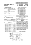
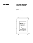
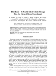
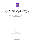
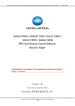
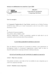
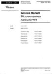
1976
Proceedings of the 4* World Congress on Intelligent Control and Automation
June 10-14, 2002, Shanghai, P.R.China
Small Sdart Distributed Control System
Yirong Yang and Shanan Zhu
Dept. of System Science and Engineering, College of Electrical Engineering
Zhejiang University, Hangzhou, P.R. China, 3 10027
E-mail: [email protected] and [email protected]
Abstract
-
This paper presents a small-scale smart
distributed control system (DCS) based on RS-485 network.
It discusses the network construction of the distributed
control system, the characteristics of RS-485, how to
1
interface
construct typical RS-485 two wire multi-drop network and
the details of the communication protocol. The smart
controller based on dual MCUs can execute many kinds of
the advanced control algorithms downloaded from the
operating station. The controller has strong ability to deal
Figure 1. System block diagram
with real-time response and great capacity of data processing,
because of the dual MCUs structure. The control is stable
industrial computer with RS-485 interface or a PC with a
and flexible, because the whole program which user has
RS232JRS485 converter in the serial port. We select the
configured in the operating station is downloaded into RAM.
ADC- 106 interface converter made by Atronix, which can
The independent watchdog circuit is also designed.
transfer the signal transmitting in an RS-232 serial port
into the balanced half-duplex RS-485 signal. There is also
I. INTRODUCTION
an RS-485 interface which adopts MAX485 transceiver
made by MAXIM Corporation in each basic controller.
Distributed control system (DCS) is a very useful
advanced automation device, but its price is very high.
Although the DCS manufacturers in the world produce
111. COMMUNICATION SYSTEM
Elements of the Communication Network
different kinds of small scale DCSs, the system is also
expensive to the small enterprises in the developing
The data transmission of the whole system is in an
country. To meet the needs of the small enterprises, we
RS-485 system. Fig. 2 is an example of a typical RS-485
design a small-scale smart distributed control system
which is cost-effective.
RS-485 is as follows:
11. SYSTEM ARCHITECTURE
two wire multi-drop network. The characteristics of
The speed of RS-485 bus is quick and the maxim
speed is 1OMbps.
The whole system includes a PC or an IPC and several
basic controllers. The PC as the operating station is used
The distance of the bus is long. For example it can
transmit data for 1200 meters by the speed of 9OKbps.
to configure h c t i o n blocks and monitor the control
It has the strong ability to eliminate common mode
process. Basic controller equipped with double CPUs is
disturbance, because each signal is transmitted in a
used to sample data and execute control algorithms. The
balanced data transmission system.
communication system adopts EINTIA-485 Standard
Each generator or dnver can drive up to 32
which is represented by RS-485. The above elements
constitute the small scale DCS. The system architecture is
receivers.
shown in Figure 1. The operating station can be an
~
0-7803-7268-9/01/$10.00
02001 IEEE.
Authorized licensed use limited to: UNIVERSITY OF PLYMOUTH. Downloaded on September 21, 2009 at 10:13 from IEEE Xplore. Restrictions apply.
June 10-14, 2002, Shanghai, P.R.China
Proceedings of the 4* World Congress on Intelligent Control and Automation
1977
Network CommunicationProtocol
The communication system between the PC and the
LJ-
.
controllers is strictly the master-slave type system in
broadcasting mode. The slave nodes are not permitted to
transmit data without a request from the master, and do
not communicate with each other. The communication
Figure. 2 Typical RS-485 two wire multi-drop network
Because of the above advantages, RS-485 is always
between the slave nodes is not direct. The message must
firstly be stored into the master node, and then be
chosen to transmit data in the industrial field control
forwarded to another slave node. Each slave must have a
system. When construct an RS-485 network, it is
unique address so that it can be addressed independent of
necessary to have a termination match the impedance of a
node to the impedance of the transmission line being used.
other nodes. The baud rate is 9600bps. The data frame
consists of ten bits: a start bit (0), eight data bits (LSB
When those impedances are not matched, the transmitted
signal is not completely absorbed by the load and a
first), and a stop bit (1). The data is in package form, and
the format of the package is shown in Table I.PC (or IPC)
portion of it is reflected back into the transmission line.
broadcasts the address of the controller to be connected,
The method to terminate data !ines is to add a resistor in
and all controllers receive the address at the same time.
parallel with the receiver A and B lines in order to match
Then each controller will compare the received address
the data line characteristic impedance specified by the
with its own address. If the address of the controller is the
cable manufacture (120Q is a common value). ADC-106
RS-232 to RS-485 converter is made by Atronix Inc. The
same as the received address, the controller is connected
and the other controllers are isolated from the network.
converter can be plug into RS-232C serial port of standard
And now the network includes only the master node and
DB9 pins and be supplied power by TXD, DTR and,RTS
signals. The power voltage must be more than 5v. The
the connected slave node so they can communicate with
each other. The communication program flow chart is
network interface of the basic controller is MAX485,
shown in Figure 4.
which is low-power transceiver for RS-485. Controlling
the COMS chip is very simple. Driver Enable (DE) and
IV. DESIGN OF SMART CONTROLLER
Receiver Enable (RE) pins are included on MAX485.
Usually, one of the output ports of the controller is
The basic controller is the core of the hardware and the
connected to both DE and RE pins. When the logic of the
software of the whole control system. Whether the design
port is low, the serial port is in the state of receiving. If
of it is good or not will influence the usability, stability,
sending the data, the output port logic must be made high.
and the ability of real-time response of the DCS. To meet
the needs of the real-time response and the handling of
The typical operating circuit is shown in Figure 3.
TABLE I
The format of the data package
Sour-
Destinat
ce
adder
Leng
Cont
-ion
-th of
-ent
address
pack
of
a-ge.
pack
-ss
;I'
age
DI
DE ROm
Dl
LE How
two
two
two
N
bytes
bytes
bytes
bytes
Figure. 3 Typical operating circuit of MAX485
Authorized licensed use limited to: UNIVERSITY OF PLYMOUTH. Downloaded on September 21, 2009 at 10:13 from IEEE Xplore. Restrictions apply.
bytes
byte
2978
June 10-14, 2002, Shanghai, P.R.China
Proceedings of the 4' World Congress on Intelligent Control and Automation
data in large quantity, we design a smart controller
Disable interrupt,
based on double MCUs. One MCU deals .with data
save PSW
sampling and real-time control, and the other deals with
data transmission. The data exchange between the two
CPUs is through the dual-ram (IDT7132). There are 8
analog input channels, 6 analog output channels( including
2 PWM channels). 16 digital input channels. 16 digital
output channels. and 2 pulse input channels. Its block
diagram is shown in Figure 5. The master CPU deals with
data sampling and signal processing and receives the
If the destinationaddress IS the
configuring program downloaded by the operating station.
Because the program downloaded form the PC executes in
RAM, the control of the system is very flexible. The
controller can execute advanced control algorithms. And
the functions of modifying parameters on-line and giving
If right ?
an alarm can be included also. Therefore the controller can
+I
be made smart. The slave CPU is used for communication.
It can receive the message from the operating station and
YES
Send error message
then send the message to the master CPU. If the master
According to the control bytes,
which PC need send
CPU sends data to the PC, it must send the data to the
send affirming message.
again.
Figure.4 Flaw chart of communicationp'ogram
RS-485
8OC 196KC
Dual-
80C 196KC
interface
slave CPU
RAM
master
Analog Interface
Figure. 5 Block diagram of the smart controller
Authorized licensed use limited to: UNIVERSITY OF PLYMOUTH. Downloaded on September 21, 2009 at 10:13 from IEEE Xplore. Restrictions apply.
Proceedings of the 4* World Congress on Intelligent Control and Automation
V. CONCLUSIONS
From above discussion, it is clear that the controller has
these advantages.
[2]
[ 11
Michael Babb, “Distributed Process Control System Integrates
hocess Design and Control”, Control Engineering, vo1.32, no. 12,
[3]
RS-422 and RS-485 Application Note, B&B Electronics Mfg. Co.
Inc, October 1997
[4] Guo Moufa“and Wang Shaobo, “The Design of RS-485 Network
and Its Applications in Industrial Monitoring Systems”, Journal Of
Fuzhou Universtity,Vo1.27, No. 1, 1999
EORGE J. BLICKLEY, “Distributed Control Systems: New and
Improved at ISA/85”, Control Engineering,
2979
November 1985, pp.81
*The watchdog circuit (h4AX705) is independent,
which can not only monitor the executing program but
also monitor the power-supply. The circuit significantly
improves system stability.
VI. REFERENCES
Shanghai, P.R.China
vo1.32, no.9 September 1985, pp150-152
*The controller has good perfonnances because of its
dual-CPU structure.
*The controller is flexible, because the whole program
is downloaded from the operating station.
June 10-14, 2002,
[SI
8x196kk-d User$ Manual, Intel Inc. 1992
Authorized licensed use limited to: UNIVERSITY OF PLYMOUTH. Downloaded on September 21, 2009 at 10:13 from IEEE Xplore. Restrictions apply.