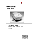
1
Repair Manual
ProPalette 8000
June 1997
Americas Business Center
Technical Services
201 Burlington Road
Bedford MA 01730
TEL: 1.781.386.5309
FAX: 1.781.386.5988
POLAROID
REPAIR MANUAL
PROPALETTE 8000 COLOR FILM RECORDER
Contents
Purpose of This Manual .....................................................................6
Manual Organization..........................................................................6
Other Service Documents...................................................................6
Important Safety Instructions .............................................................7
Electrostatic Discharge Warning ........................................................7
Note, Caution and Warning Conventions............................................7
1. ProPalette 8000 Description .............................................................8
General Description ...........................................................................8
ProPalette Features ............................................................................9
Interface Kits ...................................................................................12
Specifications...................................................................................13
2. Hardware Operating Information .................................................15
Quick Start Guide ............................................................................15
ProPalette Package Components ......................................................16
Controls, Indicators and Connectors ................................................17
Connecting to a PC Parallel Port ......................................................19
Connecting to a SCSI Interface ........................................................20
SCSI Connection Diagrams..............................................................23
Testing the Installation .....................................................................24
Using the 35mm Camera Back .........................................................25
Protecting the CRT and Camera from Dust ......................................30
Cleaning the CRT Face ....................................................................30
Cleaning the Camera Lens................................................................31
Testing the Hardware Installation.....................................................31
Troubleshooting Hardware and Film Problems .................................32
LCD Panel Messages .......................................................................34
Setup Menu Reference .....................................................................35
2
PDC-2000 Repair
Contents
3. Theory of Operation.......................................................................36
Overview .........................................................................................36
ProPalette Major Systems ................................................................38
Exposure System .............................................................................40
Digital Board ...................................................................................43
Analog Board ..................................................................................50
Slowscan Description and Imaging Sequence ...................................51
Flash Description .............................................................................57
Autoluma Description ......................................................................59
Firmware Description.......................................................................60
Camera Back Interface.....................................................................60
Keypad/LCD Interface .....................................................................62
Pacing Commands............................................................................64
4. Troubleshooting and Diagnostics...................................................66
Recommended Diagnostic Sequence ................................................66
Inspection and Cleaning ...................................................................66
Firmware Upgrade ...........................................................................66
ProPalette Startup Diagnostics and Tests .........................................68
Test Image Exposure Sequence........................................................71
Monitor Mode .................................................................................71
Error Message Redisplay..................................................................71
Serial Communication Cable ............................................................71
Digital Board Diagnostics (FPDIAG) via Host Computer.................72
Configuring a PC to Upload a Hex File ............................................74
Digital Board Interface Test .............................................................78
Analog Board Voltage Test..............................................................79
Analog Board Functional Test via Host Computer ...........................81
Analog Board Functional Test Troubleshooting ...............................83
Parallel Port Hardware Test .............................................................83
SCSI Interface Hardware Test .........................................................83
Image Evaluation .............................................................................83
Error Message and Symptom Tables ................................................87
5. Test Stand Operation ...................................................................108
Test Stand Description...................................................................108
Test Stand Functions......................................................................109
Test Stand Calibration....................................................................109
Connecting ProPalette and Powering Up the Test Stand.................110
Upgrading ProPalette Firmware .....................................................113
Testing the Digital Board ...............................................................114
Checking Yoke Position.................................................................117
Assembly After Yoke Adjustment ..................................................124
3
Contents
ProPalette 8000 Repair
5. Test Stand Operation (Continued)
Testing the Analog Board ..............................................................127
Aligning the ProPalette ..................................................................131
Focusing the 35mm Camera ...........................................................134
6. Parts Replacement........................................................................139
Removal of the Front Bezel Assembly ............................................140
Installation of the Front Bezel Assembly.........................................140
Removal of the LCD Keypad Assembly..........................................141
Installation of the LCD Keypad Assembly ......................................141
Removal of the LCD Panel.............................................................142
Installation of the LCD Panel .........................................................142
Removal of the Front Bezel Door...................................................143
Installation of the Front Bezel Door ...............................................143
Removal of the Power Switch ........................................................144
Installation of the Power Switch.....................................................144
Removal of the Camera Plate Assembly..........................................145
Installation of the Camera Plate Assembly ......................................146
Removal of the Camera Cable (Teka) Connector............................146
Installation of the Camera Cable (Teka) Connector ........................147
Removal of the Top Cover and Rear Panel Assembly .....................148
Installation of the Top Cover and Rear Panel Assembly..................149
Removal of the Stepper Motor.......................................................150
Installation of the Stepper Motor....................................................151
Removal of the Autoluma Board Assembly ....................................152
Installation of the Autoluma Board Assembly.................................153
Removal of the Wheel Position Sensor (Photo Interrupter).............153
Installation of the Wheel Position Sensor (Photo Interrupter) .........155
Removal/Installation Of The LCD Interface Cable..........................156
Removal/Installation of the Camera Cable Assembly ......................156
Removal of the Electronics Drawer ................................................158
Installation of the Electronics Drawer.............................................159
Removal of the Digital PC Board Assembly ...................................160
Installation of the Digital PC Board Assembly ................................160
Replacement of the Camera Power Fuse.........................................160
Removal of the Analog PC Board ..................................................161
Installation of the Analog PC Board ...............................................161
Removal of the Low Voltage Power Supply...................................162
Installation of the Low Voltage Power Supply ...............................162
Removal of the Light Box Assembly ..............................................163
Installation of the Light Box Assembly ...........................................165
Disassembly of the CRT.................................................................168
4
PDC-2000 Repair
Contents
6. Parts Replacement (Continued)
Reassembly of the CRT..................................................................169
Removal of the Front Plate Assembly.............................................169
Installation of the Front Plate Assembly..........................................170
Removal of the Filter Wheel...........................................................171
Installation of the Filter Wheel .......................................................171
Replacement of the Filters..............................................................172
Removal of the High Voltage Power Supply ..................................174
Installation of the High Voltage Power Supply ...............................174
7. Schematics ....................................................................................175
Appendix A. Film Table List............................................................195
Appendix B. Abbreviations in This Manual ...................................197
5
ProPalette 8000 Repair
Purpose of This Manual
This manual is intended to be a reference and training guide for authorized service technicians
who install, troubleshoot and repair the Polaroid ProPalette 8000 Color Film Printer.
Manual Organization
This manual is organized into six sections:
1. ProPalette 8000 Description Describes the ProPalette 8000 Color Film
Printer, along with its features, components and specifications.
2. Hardware Operating Information Setup, operating and troubleshooting
instructions provided to users in ProPalette 8000 Hardware Manual
(reproduced in this manual for the convenience of service technicians).
3. Theory of Operation Detailed explanations of ProPalette system and
component functions for use in diagnosing problems and performing other
service.
4. Troubleshooting and Diagnostics Instructions for diagnosing image defects,
errors and other malfunctions, along with likely causes and suggested
corrective action.
5. System Test Stand Instructions for calibrating and adjusting ProPalette for
optimum performance.
6. Parts Replacement Instructions for replacing individual ProPalette
components.
7. Schematics Selected ProPalette schematic drawings for use in
troubleshooting.
Other Service Documents
In addition to this manual, ProPalette 8000 service personnel should have access to the following
documents:
ProPalette 8000 Parts Catalog
ProPalette 8000 Hardware Manual
Palette Export Software User Guide
6
ProPalette 8000 Repair
Important Safety Instructions
When servicing the ProPalette 8000, always take the following safety precautions:
• Read and understand all applicable service procedures before proceeding.
• Turn off and unplug the unit before servicing.
• When service procedures require the unit to be plugged in with the cover off, take
special care to avoid contact with high voltage connections, wires and components.
Warning
The ProPalette 8000 Color Film Printer has hazardous internal
voltages. Maintenance operations, especially those performed with the
printer cover removed, should be performed only by qualified service
personnel.
Electrostatic Discharge Warning
ProPalette circuitry can be easily damaged by small, unnoticeable static discharges. Always use
an anti-static mat and wrist strap when removing the ProPalette cover or when servicing the
unit with the cover removed.
Note, Caution and Warning Conventions
The use of notes, cautions and warnings in this manual follows these conventions:
Note Information that is essential to highlight.
Caution Procedure or other information that, if not strictly observed, could result in
equipment damage.
Warning Procedure or other information that, if not strictly observed, could result in
personal injury or loss of life.
7
ProPalette Description
ProPalette 8000 Repair
1. ProPalette 8000 Description
General Description
The Polaroid ProPalette 8000 (Figure 1-1) is a digital, photographic-quality printer designed for
the mid-range color film recorder market. With a 7-inch CRT and custom optics to reduce spot
size, ProPalette 8000 produces higher resolution images (8192 x 5462 maximum) than other film
recorders in its product category.
The ProPalette 8000 prints on positive and negative 35mm films. Custom film tables also allow
printing on E6, C41 and Polaroid instant films. In addition, optional cameras and custom film
tables are available for 6x7 (120/220), 4x5 and 35mm bulk roll films. See Appendix A (page 195)
for a complete list of ProPalette film tables.
Compared with other Polaroid Palette film recorder models, the ProPalette 8000 offers higher
resolution, improved geometry, reduced vignetting (brightness falloff in corners) and easier
manufacturing. ProPalette is also designed for faster printing: exposing a 4-kilobyte 35mm image
requires less than 60 seconds.
ProPalette optics include dichroic filters to maximize transmittance and improve color cutoff.
Also, a custom six-element 43.53mm/F6.6 glass lens and high-resolution 7-inch CRT with a
proprietary anti-reflection and anti-static coating minimize spot size and maximize sharpness and
color saturation.
Figure 1-1. ProPalette 8000 film recorder
8
ProPalette 8000 Repair
ProPalette Description
Brightness and color balance are automatically calculated before exposure of each image.
Automatic digital geometry correction is provided for circles and lines to eliminate pincushion,
barrel and keystoning. The system’s electronics adjust the focus of each image on the CRT and
use custom lookup tables for horizontal and vertical planes.
ProPalette 8000 is simple to set up and use with either Macintosh or PC workstations. Its 35mm
camera automatically loads film and counts exposures, and it automatically detects and sets up for
different film types through DX encoding.
The 20-character LCD panel guides the user through setup and provides system status
information. This information includes:
•
•
•
•
•
•
•
Film type
Frames remaining
Output resolution
Exposure time
SCSI ID setting
Firmware version number
Error messages and codes
ProPalette can be accessed from Macintosh and PC computers via Adobe Photoshop and other
Photoshop plug-in compatible applications with the Polaroid Palette Export plug-in module. This
module is included in both Macintosh and PC interface kits.
ProPalette Features
Feature
Description
Benefit
Custom optics
Custom 6 element 43.53mm/F6.6
glass lens; dichroic filters which
combine high transmittance with
sharp color cut-off; custom CRT
face plate optics
Minimize spot size and
maximize color saturation
Automatic exposure and
color balance control
Electronics for automatically
setting optimum brightness and
color balance before exposure of
each image
Bright images and accurate
colors
9
ProPalette Description
Feature
ProPalette 8000 Repair
Description
Benefit
Geometry correction
Distortion-free images
Automatic digital correction of
geometry and linearity to eliminate
pincushion, barrel and keystoning
Dynamic focus
adjustment
Automatic electronic focus of the
image on the internal CRT using a
lookup table customized for the
individual unit
Consistent clarity and
sharpness
High-resolution, 7-in.
CRT
Large, precision CRT with
proprietary anti-reflection and
anti-static coating
Consistent clarity and
sharpness
8K resolution
Variable resolution up to 8192
Clearly defined details and
horizontal and 5462 vertical pixels text
36-bit color depth
24-bit images with precision of 36
bits per pixel
Printing in 16.8 million
colors, from a palette of 68
billion colors
Automated 35mm
camera
Fast, automated film loading and
exposure counting, with film-type
recognition through DX film
encoding; automatic film rewind
Simple, efficient operation
and high productivity
LCD display on front
panel
20-character x two-line interactive Easy to learn operation and
display provides setup and status
immediate understanding of
information
current status for efficiency
and productivity
Flash memory
4-megabyte DRAM, 512-kilobyte
flash memory
Fast, simple upgrading as
enhancements become
available
Multiple film formats
Software and hardware support
for 35mm, 4x5, 6x7 and 35mm
bulk camera backs; custom film
tables provided for E6, C-41 and
Polaroid instant films
Flexibility to handle
expanding or changing
imaging needs
10
ProPalette 8000 Repair
Feature
ProPalette Description
Description
Benefit
Self diagnostics
Unit performs a self-diagnostics
routine at startup. Routine can
also be initiated via the keypad or
host computer, if necessary
Helps isolate problems
quickly and without special
tools or software
No potentiometer
adjustments
Manual optimization unnecessary
Fast, automated, accurate
calibration of individual units
Operating and service
Total exposures, film type used
history stored in memory for each, service history
information recorded in
nonvolatile memory for reference
Up-to-date operating and
service history always
available to service
technicians
Ports
ProPalette 8000 has four ports (Figure 1-2):
• Centronics parallel
• Synchronization IEEE 1284 style (supporting firmware not
available on early units)
• SCSI-1
• RJ-11 serial (available to service personnel only)
Figure 1-2. ProPalette ports
11
ProPalette Description
ProPalette 8000 Repair
Interface Kits
The ProPalette software/interface components are summarized in Table 1-1.
Table 1-1. ProPalette Software/Interface Matrix
Ver.
Operating
Description or
Name
No.
Vendor
System
Comments
Palette for Windows
1.0.4 Polaroid
Windows
Film table installer
SuperPrint
3.1.3 Zenographics Windows
Sold directly by vendor
Polaroid Palette Export
1.1.0 Polaroid
Windows
Photoshop plug in
Networking Multi-User Pack
Graphx
Windows
5-user license
RasterPlus 95/ProPalette
Graphx
Windows 95
Postscript RIP
RasterPlus 95/Digital Palette
Graphx
Windows 95
Postscript RIP
RasterPlus 95/Upgrade for all
Graphx
Windows 95
Postscript RIP
Polaroid Palette Export
1.1.0 Polaroid
Macintosh
Photoshop plug in
Networking Multi-User Pack
GCC
Macintosh
5-user license
VBS Professional Output Manager
VBS
Macintosh
Postscript RIP
Si Print Assistant
Nutting
Macintosh
NPKK driver
ImagePrint
1.42 Polaroid
DOS
CI&HR for CGM, TGA
Palette for Macintosh
2.15 GCC
Macintosh
RasterPlus P/S for Digital Palette
DOS
Rasterizer
Pisa Systems Mac/Windows Hardware RIP
ImageBox FX
Prime Option Mac/Windows Hardware RIP
This table is subject to change without notice.
Windows Kit
The ProPalette Windows kit consists of the following:
Palette for Windows. Setup program for installing all necessary software.
Includes film tables for E6, C-41 and instant films. (Required for any software
installation.)
Zenographics SuperPrint. Includes Windows printing utility, networking
utility, background-printing utility, drivers for ProPalette 8000 and other
Polaroid color film recorders, drivers for major black and white printers.
Polaroid Palette Export. Plug-in module compatible with Adobe Photoshop
and other popular image processing applications
Parallel cable. Allows ProPalette to be connected to the PC via a parallel port.
Unlike earlier Polaroid film printers, DOS is not a supported environment.
12
PID
No.
620238
619117
621667
621668
621665
620237
619785
618336
618337
618335
ProPalette 8000 Repair
ProPalette Description
Macintosh Kit
The ProPalette Macintosh kit consists of the following:
Palette for Macintosh. Chooser-level driver for direct imaging from Macintosh
applications, networking utility and background printing utility.
Polaroid Palette Export. Plug-in module compatible with Adobe Photoshop
and other popular image processing applications.
SCSI cable and terminator. Allows ProPalette to be connected to a Macintosh
or added to an existing SCSI chain.
Optional Components
Polaroid offers the following optional software and hardware for use with the ProPalette 8000:
• Zenographic’s Networking Multi-User Pack
• Palette for Macintosh Networking Multi-User Pack
• VBS (Macintosh) software rasterizer
• Graphx (PC) software rasterizer
• Pisa Systems hardware rasterizer for Windows 95, Macintosh or Unix
Specifications
CRT
High Resolution 7" CRT
Optics
Dichroic filters
Custom 43.53mm/F6.6/, 6-element glass lens
Custom CRT face plate optics
Image precision
Automatic exposure and color balance control
Geometry correction
Dynamic focus circuitry
Image quality
Any resolution up to a maximum resolution of 8192 horizontal x 5462
vertical lines
Color depth
36 bits per pixel
16.8 million colors per image out of a 68 billion palette
Camera
Automated 35mm camera back
13
ProPalette Description
ProPalette 8000 Repair
Controls
20 character by 2 line interactive LCD front panel display
Memory
4 MB DRAM, 512 KB flash
Hardware
requirements
PC environment:
• 386SX or faster processor
• Windows 3.1 or higher
Macintosh environment:
• Apple Macintosh 11 or higher including Quadra, Centris, Powerbook,
Power Mac
• System 6.07 or later
Unix environment:
Supported through third party manufacturer
Hardware interface
Parallel and SCSI
Postscript
compatibility
Software and hardware support through third party manufacturers
Network printing
Supported via software drivers
Optional cameras
6 x 7 (120/220) back, 6 x 8 (120/220) back, 4 x 5 back, bulk load 35mm
back available through third party manufacturer
Power source
90-240 Vac, 50-60 Hz
Power consumption
Under 45 watts
Environment
Temperature: 65 to 100 degrees Fahrenheit
Storage Temperature: -20 to 160 degrees Fahrenheit
Relative Humidity: 5 to 90 % non-condensing
Dimensions
11" x 28" x 8.5", 28 x 71 x 21.6 cm
Weight
34 lb., 15.4 kg
Certifications
UL, FCC, TUV, C-UL, CE and EN55022
Warranty
One year parts and labor
Extended warranty available
14
ProPalette 8000 Service
Hardware Operating Information
2. Hardware Operating Information
For the convenience of repair technicians, information in this chapter is reproduced from the
ProPalette 8000 Hardware Manual provided to ProPalette purchasers.
Quick Start Guide
1. Turn off the computer and all equipment connected to it.
2. Use the cable provided to connect the ProPalette recorder to the computer.
3. Plug the power cord into the recorder, then into a power outlet.
4. If you are using the SCSI interface, be sure the SCSI connections are correct and
properly terminated.
Note
For termination, use the recorder’s internal termination (see
“Changing Termination” on page 21) or an external terminator.
5. Turn on the ProPalette, then the computer.
6. Load film into the camera/adapter.
7. Install the software according to instructions packaged with it.
15
Hardware Operating Information
ProPalette 8000 Service
ProPalette Package Components
The ProPalette 8000 package contains the following components:
•
•
•
•
Recorder (a in Figure 2-1)
Power cord (b in Figure 2-1)
35mm camera back (c in Figure 2-1); comes mounted on recorder
Hardware manual and registration card (not shown)
In addition to the package components, ProPalette comes with one of the software kits described
below.
Figure 2-1. ProPalette 8000 components
Palette for Macintosh Software Kit
The Palette for Macintosh software kit consists of the following:
•
•
•
•
•
Macintosh SCSI cable (25-pin to 50-pin)
SCSI terminator
Polaroid software
Polaroid Palette for Macintosh manual
Polaroid Palette Export for Macintosh (Adobe Photoshop plug-in) software
and instructions
Digital Palette for Windows/ProPalette for Windows Software Kit
The Digital Palette for Windows/ProPalette for Windows software kit consists of the following:
16
ProPalette 8000 Service
•
•
•
•
•
Hardware Operating Information
Host interface parallel cable
Polaroid ProPalette for Windows installation disk
SuperPrint software for windows disk
SuperPrint user’s manual
Polaroid Palette Export for Windows
Controls, Indicators and Connectors
Front (Without Camera)
The following controls, indicators and connectors on the front of the ProPalette unit are shown in
Figure 2-2:
a. Message panel (see page 34 for messages)
b. Keypad
c. Camera connector
d. Attachment holes for optional camera backs
e. Camera locking lever
f. 35mm Camera positioning holes
g. Power OFF/ON (0/1) switch (beneath door)
h. Lens cap holder and lens cap
i. Front cover
Figure 2-2. Front controls, indicators, features
17
Hardware Operating Information
ProPalette 8000 Service
Keypad
The ProPalette keypad controls and indicators are identified in Figure 2-3.
Figure 2-3. Keypad controls and indicators
Rear and Bottom Panels
The following connectors and features on the rear and bottom panels of the ProPalette unit are
shown in Figure 2-4:
a. Service port (for use by service technicians only)
b. Parallel port
c. Two SCSI ports (The SCSI ID number is selected via the keypad; see page
22.)
d. Reset button
e. Service port (for use by service technicians only)
f. Power connector
g. CRT access door (underneath unit)
18
ProPalette 8000 Service
Hardware Operating Information
Figure 2-4. Rear and bottom panels
Connecting to a PC Parallel Port
Caution
All connections must be made with the power off on both the
recorder and the computer. Pay strict attention to the sequence of
instructions in this section. Failure to comply may result in damage
to the computer and/or the recorder. Such damage is not covered
by the warranty.
1. Turn off the computer and make sure the recorder power switch is in the Off (0)
position (see the left panel of Figure 2-5).
Figure 2-5. Connecting to the parallel port
19
Hardware Operating Information
ProPalette 8000 Service
2. Connect one end of the parallel cable to the parallel port of the recorder by squeezing
the two side tabs, pushing the connector into the port, then releasing the tabs (see the
right panel of Figure 2-5).
3. To connect the recorder to your computer, plug the other end of the cable into the
parallel port. Fasten the connector with the two thumbscrews.
Connecting to a SCSI Interface
Warning
All connections must be made with both ProPalette and computer
power off. Pay strict attention to the sequence of instructions in
this section. Failure to comply may result in damage to the
computer or the recorder. Such damage is not covered by the
warranty.
The Polaroid ProPalette 8000 includes a SCSI interface (Small Computer System Interface), a
standardized cable system and communications protocol that allows connection of up to seven
SCSI peripheral devices to a computer.
The SCSI interface is standard for Macintosh computers. For the PC, you must have a SCSI host
adapter installed in your computer. Support for SCSI host adapters is provided by the software
application; consult your software documentation for up-to-date information on compatibility. See
the instructions provided with the SCSI adapter for proper installation.
SCSI Guidelines
The SCSI system uses special cables and termination to achieve communication between the
computer and peripheral devices. To function properly, the combined length of the entire cable
system must not exceed 19 1/2 feet (6 meters) and must include the appropriate number of
terminators. A SCSI chain must always be terminated at both ends. Incorrect termination can
permanently damage the computer, film recorder, or any other device along the SCSI chain. Refer
to the following guidelines and diagrams for more information.
Termination
The SCSI chain must be terminated at both ends of the chain. The beginning of the chain is
typically the computer. In a PC, make sure the SCSI host adapter is terminated; see instructions
for the SCSI adapter. (However, if you have an internal SCSI hard drive and only one SCSI
adapter, then the hard drive should be terminated and not the adapter.) Most Macintosh
computers include a hard disk which is internally terminated. (If your computer is not internallyterminated, you must place an external terminator on the first device after the computer, between
the device and the SCSI cable to the computer.)
20
ProPalette 8000 Service
Hardware Operating Information
Intermediate devices in the chain should not be terminated. If you have an internally terminated
device, place it at the end of the chain. (Check the manual for the device to determine whether it
is internally terminated.) If none of your devices are internally terminated, place the external
terminator provided on the last device.
The ProPalette is shipped with termination turned off . The recorder can be terminated externally
by using the terminator provided, or internally by using the keypad as described in “Changing
Termination” below.
Note
If you turn on internal termination, do not terminate externally.
PowerBook note: According to Apple Computer, even though this computer has an internal hard
disk, you should treat it as an unterminated device. This means that you must have two
terminators on the SCSI chain; for example, one on the end of the PowerBook pigtail and one on
the ProPalette. The documentation included with your PowerBook has more information.
Macintosh IIfx: If you are connecting the recorder to a Macintosh that requires special
termination, such as the Macintosh IIfx, use only the special black terminator shipped with the
Macintosh IIfx.
Changing Termination
The ProPalette is shipped with termination off. If you wish to turn termination on internally
(rather than use the external terminator), do the following:
1. Turn off your computer and all other SCSI devices.
2. Connect the power cord to the recorder and into a grounded power supply.
3. Turn on the recorder. After a moment, the message panel will display “Ready.”
4. Press the Escape key to get to the Change Setup menu. Press the Down key until
“SCSI Terminated?” is displayed.
5. Press the Select key. Then press the Down or Up key to display “Yes.” (To return to
termination off, select No.)
6. Press the Select key to enter your selection.
7. Press the Escape key twice to return to the “Ready” message.
8. Press the reset button on the back of the recorder, or turn the recorder off and on, for
the selection to take effect.
21
Hardware Operating Information
ProPalette 8000 Service
Connection Tips
• When you connect or disconnect a SCSI device, make sure all SCSI devices have their AC
power switched OFF.
• Always make SCSI connections firmly, connecting the clips or tightening the screws that secure
cables and terminators. Most problems with SCSI devices are connection problems along the
SCSI chain.
• Some devices, such as the ProPalette, have two SCSI ports. The cable can be connected to
either port without affecting the performance of your equipment.
• Each device on a SCSI chain must have a unique SCSI ID number. These numbers are
described in the following section.
• Wherever a 50-to-50 pin cable is required, be sure to use a cable which meets the SCSI-2
specification, such as an Apple cable.
• If you are using a PC, the ProPalette can be connected to two host computers at once; one via
the parallel connector and one via the SCSI connector. The recorder will image in the order the
signal is received.
Changing the SCSI ID
Caution
To prevent damage to the hardware and software, read this section
before turning on the system.
Each device on a SCSI chain must have a unique SCSI ID number from 0 to 7. The ProPalette is
set at the factory to SCSI ID number 4. If this number conflicts with any other device on the SCSI
chain, you must change either the SCSI ID number of the recorder or the SCSI ID number of the
other device. Refer to the SCSI hardware manual for more information.
To change the SCSI ID number, do the following:
1. Disconnect the ProPalette from your computer and all other SCSI devices.
2. Connect the power cord to the recorder and into a grounded power supply.
3. Turn on the recorder’s power switch. The ready message will be displayed.
4. Press the Escape key to reach the Change Setup menu. Press the Down key until
“SCSI ID?” Is displayed. Press the Select key; your current ID setting is indicated.
Press the Down key until the desired number is displayed (a number from 0 to 7).
22
ProPalette 8000 Service
Hardware Operating Information
5. Press the Select key to enter your selection.
6. Press the Escape key twice to return to the Ready mode.
7. Press the reset button on the back of the recorder, or turn the recorder off and on, for
the selection to take effect.
Caution
If two devices on a SCSI chain have the same SCSI ID number,
neither will work correctly, and data may be damaged when you
turn on the devices.
SCSI Connection Diagrams
A variety of system configurations is possible, depending on what peripherals are connected to the
system used with ProPalette.
The diagrams below show many different combinations. Find the appropriate configuration for the
hardware, and follow the connection diagram and instructions.
Recorder is Only SCSI Device
The internal SCSI hard disk or the SCSI host adapter is internally terminated. Therefore, you
need to add the terminator to the recorder as shown in Figure 2-6 (between the cable and the
recorder, or on the second SCSI port).
Note
If you prefer, you can turn the termination on internally, rather than
use the external terminator. See “Changing Termination” on page
21.
Figure 2-6. Connection when recorder is only SCSI device
23
Hardware Operating Information
ProPalette 8000 Service
Multiple External SCSI Devices, One Internally Terminated
Place the device with the internal terminator at the end of the chain (Figure 2-7) and do not add
any additional terminators. If any other external device has an internal terminator, the terminator
will have to be removed according to the manufacturer’s directions.
Figure 2-7. Connecting multiple external SCSI devices, one internally terminated
Multiple External SCSI Devices, None Internally Terminated
Place a terminator between the SCSI cable and the last external SCSI device on the chain (Figure
2-8). If one external device has an internal terminator, see the example above.
Figure 2-8. Multiple external SCSI devices, none internally terminated
Testing the Installation
To verify that the ProPalette hardware is installed correctly, make a test image by using the
keypad. See “Testing the Hardware Installation” on page 31.
24
ProPalette 8000 Service
Hardware Operating Information
Using the 35mm Camera Back
35mm Camera Back Description
The 35mm camera back (Figure 2-9) provided with the recorder features automatic film loading,
advancing and rewinding for maximum convenience. The camera can detect the length of the film,
and counts frames as exposures are made. This information is displayed on the message panel for
reference.
Refer to Figure 2-9 for the location of the following camera back components:
a.
b.
c.
d.
e.
f.
Film door button
Film ID window
Film door
Edge connector
Lens
Positioning pins
Figure 2-9. 35mm camera back
Loading 35mm Film
1. Turn the recorder on. Slide the film door button down (Figure 2-10, left) and open the
door.
Figure 2-10. Opening the door and inserting the film cassette
25
Hardware Operating Information
ProPalette 8000 Service
2. Insert the film cassette at an angle into the chamber as shown in Figure 2-10 (right
panel). The pin in the chamber fits into the hole on the bottom of the cassette. Push it
all the way in, so that the film lies flat in the track. When loading Polaroid Polachrome
film, remember that the emulsion (dull side) faces away from the lens. This is different
from conventional film, in which the emulsion faces the lens.
3. Pull the end of the film out carefully, until the end is aligned with the white triangle at
the lower right, near the take-up spool (a in Figure 2-11). If you pull it out too far,
take the cassette out and wind the extra film back in by turning the black knob at the
top of the cassette.
4. When the end of the film is properly aligned with the white triangle, close the film door
until it clicks shut. The message panel will display “Loading film.” The film will
automatically advance to the first exposure, and the message panel will display the
number of frames available (for example, “24 Frames Left of 24” for a 24-exposure
roll).
Note
You may be able to expose more frames than indicated by the film
container. For example, you may be able to make 13 exposures on a
12-exposure roll. In this case, the message panel will display “13
Frames Left of 13.” The film unwinds to the end of the roll when
first loaded, and winds back into the cassette frame by frame with
each exposure. This lets the camera determine the actual number of
exposures available, and it protects exposed images if the camera
door is inadvertently opened.
Figure 2-11. Aligning the end of the film
26
ProPalette 8000 Service
Hardware Operating Information
5. You can store the empty film box under the locking lever, then close the front door
(Figure 2-12).
Figure 2-12. Closing the front door
Locking the Film Type Via the Keypad (Remote Users)
The film type must always be selected in the software, and it must match the film loaded into the
recorder to ensure proper color balance and exposure. If the recorder is on a network, it may be
inconvenient for remote users to confirm which film type is currently loaded into the recorder. If
so, you can “lock in” the film type you have just loaded using the keypad. Doing so will prevent
users from making exposures on the incorrect film type (an error message will alert the user).
When the film type is “unlocked” (not selected via the keypad), no error message is sent. In this
case, remote users should check which film is loaded before imaging.
To lock the film type:
1. Press the Escape key to reach the Change Setup menu.
2. Press the Down key until “Lock Film Type?” is displayed. Press the Select key.
“*Unlocked” or the name of the currently locked film is displayed.
3. Press the Down (or Up ) key to display the film type that is currently loaded. Or, select
Unlocked to allow any film type to be selected in the software.
4. Press the Select key to enter the selection. An asterisk (*) will appear next to your
selection to indicate it has been selected. Press Escape twice to return to the Ready
message.
Using Polaroid Polachrome Instant Film
It is more convenient to process Polaroid Polachrome HC instant 35mm film if there is a short
length of film (a “leader”) remaining after the roll is exposed. To set the camera back to leave a
leader when rewinding, do the following:
1. Press the Escape key to reach the Change Setup menu.
27
Hardware Operating Information
ProPalette 8000 Service
2. Press the Down key until “Leave Leader?” is displayed.
3. Press the Select key, then press the Down key to display “Yes.”
4. Press the Select key to enter the selection. Press Escape twice to return to the Ready
message.
Note
Remember to select No under “Leave Leader?” when you reload
conventional 35mm film, which should be completely rewound
when exposed.
Making Exposures
Once you have loaded the film, the Ready status message will be displayed on the message panel.
You are now ready to begin initiating exposures from the software. (Be sure to select the correct
film type in the software.)
When you begin your first exposure, the unit may do a brief calibration routine first (the message
panel will display “Calibrating,” then “Calculating Grid”).
During the exposure, the message panel will display “Exposing RED,” “Exposing GREEN,” and
“Exposing BLUE” as it exposes the three color components of your image through the three
filters.
After each exposure, the panel will count down the frames available (for example, “23 Frames
Left of 24”). When the last exposure is finished, the message panel will display “Out of Film.”
Remove the exposed film as described in the following section.
Note
When you turn off the recorder with a partially exposed roll loaded,
the recorder keeps the status information in memory and will
redisplay the correct frame count when you turn on the recorder
again.
Removing Exposed Film
When you are finished exposing a roll of 35mm film, the camera will automatically rewind the
film. The message panel will then display “Out of Film.” Open the front door of the recorder,
open the film door, and remove the film cassette. The film should be completely rewound into the
cassette except when using Polaroid Polachrome HC instant 35mm film; see “Using Polaroid
Polachrome Instant Film” on page 27.
28
ProPalette 8000 Service
Hardware Operating Information
Removing a Partially Exposed Roll
To rewind a partially exposed roll of film, press the Escape key to display the Change Setup
menu. Press the Down key until “Rewind Film” is displayed. Press the Select key. The film will
rewind, and the message panel will display “Out of Film” when done. Remove the film.
Note
Do not try to reinstall a partially exposed roll of film.
Cancelling an Exposure
If you change your mind about exposing a particular image, you can interrupt the exposure in
mid-cycle instead of waiting for the exposure to finish. Press the Escape key to display the Setup
menu. Press the Down key until “Cancel Exposure?” is displayed. Press the Select key and the
exposure will be halted. The film will be advanced for the next exposure.
Advancing Film
If you need to advance film (leave unexposed frames) during a session, press the Escape key to
display the Change Setup menu. Press the Down key until “Advance Film?” is displayed. Press the
Select key; the film will advance one frame. To advance the film by more than one frame, repeat
this sequence the desired number of times.
Note
This option is useful if a power failure occurs during an exposure.
Advance the film by one frame, then reshoot the image on the next
frame. Or, if you accidentally opened the film door when a partially
exposed roll was loaded, advance the film by a few frames to
bypass the light-fogged area of film.
Removing and Replacing the 35mm Camera Back
To remove the 35mm camera back:
1. Open the front cover of the recorder.
2. Move the locking lever to the unlocked (¡) position (Figure 2-13, left).
3. Carefully pull the camera back straight off (Figure 2-13, right). Replace the lens cap,
which is stored in the front cover, while the camera is not in use.
29
Hardware Operating Information
ProPalette 8000 Service
Figure 2-13. Removing and replacing the camera back
To replace the camera back:
1. Remove the lens cap and store it in the holder in the front door.
2. Be sure the locking lever is set to the unlocked (¡) position.
3. Push the 35mm camera back gently but firmly onto the mounting plate so the posi tioning pins fit in the holes, and so the edge connector fits snugly into the slot in the
recorder. Turn the locking lever to the locked (l) position.
Protecting the CRT and Camera from Dust
Follow these guidelines to protect the CRT and camera from dust:
• Keep a camera back on the unit when it is not in use.
• When the camera back is not mounted on the recorder, use the lens cap provided.
Cleaning the CRT Face
The CRT inside the recorder has an anti-static coating to help protect it from smoke and dust
particles. But if dust appears on the CRT, clean it as follows.
1. Turn the power off and disconnect the power cord.
2. Turn the recorder on its side.
3. Unscrew and remove the access door on the bottom.
4. Carefully reach in and remove the dust on the surface of the CRT with a dry cotton
swab (Figure 2-14). Avoid touching the filter wheel and filters.
30
ProPalette 8000 Service
Hardware Operating Information
Figure 2-14. Cleaning the CRT face through the bottom access door
Cleaning the Camera Lens
Remove the 35mm camera back as described on page 29 and hold it with the lens facing up.
Remove as much dirt as possible with an aspirator, pressurized air, or a camel hair brush, available
at a camera store. If necessary, wipe the lens with a cotton-tipped swab moistened with lens
cleaner (Figure 2-15). Do not soak the swab so that the lens is flooded with cleaner. Examine the
surface of the lens for scratches and replace it if any are found.
Caution
When cleaning the lens, do not use strong detergent solutions,
abrasives of any sort, or aromatic solvents such as acetone or
MEK.
Figure 2-15. Cleaning the camera lens
Testing the Hardware Installation
To test that your recorder is imaging properly, you can use the keypad to initiate a test image that
does not require connection to a computer.
1. To check that the recorder is going through an exposure cycle, remove the 35mm
camera so you can observe the CRT through the lens opening in the recorder.
31
Hardware Operating Information
ProPalette 8000 Service
2. With the Ready message displayed, press the Escape key to reach the Change Setup
menu.
3. Press the Down key until “Diagnostics?” is displayed. Press the Select key, then press
the Down key to display “Expose Test Image?”
4. Press the Select key to begin the test exposure cycle and look at the CRT through the
camera opening. You will see a row of red spots moving down the screen, and a
horizontal line flashing intermittently. Then this cycle will repeat through the green and
blue filters. (Figure 2-16 shows the image this pattern would create on film.)
If you do not see the spots and horizontal line described in step 4, there is a problem with the
hardware or hardware installation. Check your cable connections before looking further.
If the test was successful but you cannot image from a software package, the problem could be
software-related. Please check the software manual or contact the manufacturer of the application
software.
Figure 2-16. ProPalette test image
Troubleshooting Hardware and Film Problems
This section describes symptoms and solutions for problems with hardware setup and use of the
35mm camera/adapter. Refer to the software manual for troubleshooting software problems. Also
refer to Chapter 4 for additional troubleshooting information.
Black image (film not exposed): The shutter did not open, or the lens cap was left on the
camera.
Random black spots: Caused by dirt specks on the CRT. Clean the CRT as described on page
30.
32
ProPalette 8000 Service
Hardware Operating Information
Dark, or pale colored horizontal lines across image: Make sure the recorder is properly
grounded (including extensions and multiple outlet strips), use only the cables supplied with the
recorder, and protect the unit from bumps and vibrations during exposure.
Image too light or dark; incorrect color balance: Make sure the correct film type has been
specified in the software; see the software instructions for details.
Color Balance and Exposure for Negative Film
When using color negative film, color balance and exposure can vary over a wide range due to the
variability of processing and printing at the processing lab. If exact color matching is important,
shoot the test image at the beginning of each roll and have a custom lab calibrate the equipment to
that image for color balance and exposure before printing the roll. The image is equivalent to an
18% gray card.
Macintosh users: The test image GRAYCARD is in the Print Me Later folder.
PC users: The test image GRAYCARD.TIF is copied onto your hard drive at installation. Import
this file into your application software for imaging.
Running a Self-Test
If you wish to run the diagnostic self-test that the recorder performs at power-up without turning
the recorder off and on again, you can do so using the keypad.
Press the Escape key to reach the setup menu. Press the Down key until “Diagnostics?” is
displayed. Press the Select key, then press the Down key to display “Run Startup Diags?” Press
the Select key to begin the brief self-test.
Redisplaying an Error Message
When the system detects one of a number of hardware or software problems, it briefly displays an
error message on the message panel. The same message may also appear on your computer. The
recorder will automatically reset.
If the problem persists, press the Escape key to reach the setup menu. Press the Down key until
“Diagnostics?” is displayed. Press the Select key, then press the Down key to display “Show Last
Error?” Press the Select key; the most recent error message will be displayed for your reference.
33
Hardware Operating Information
ProPalette 8000 Service
LCD Panel Messages
The message:
is displayed when:
Ready
x Frames Left of Y
Unit is ready to expose.
Film is loaded and there are frames left to expose (where x is the
number of frames left and y is the length of the roll).
Note: To reach Change Setup? press Escape (see the following
section, “Setup Menu Reference”).
Loading Film
Film is being loaded after the film door is closed
Calibrating/
Calculating Grid
You initiate the first exposure of each session, and as necessary after
that. “Calculating Grid” appears only when resolution has changed.
Exposing RED
The red data is being exposed through the red filter.
Exposing GREEN
The green data is being exposed through the green filter.
Exposing BLUE
The blue data is being exposed through the blue filter.
Rewinding Film
Film is being rewound at the end of the roll, or after you select
Rewind Film? to rewind a partially exposed roll (see the following
section, “Setup Menu Reference”).
Out of Film
Film is completely exposed and ready to be removed, or no film is
loaded.
Change Setup?
You press Escape from the Ready message. Select this to change
setup (see the following section, “Setup Menu Reference”).
[One of several error
messages]
There is a problem with the recorder or the software. The recorder
will automatically reset. To view the error message again, see
“Redisplaying an Error Message” on page 33.
34
ProPalette 8000 Service
Hardware Operating Information
Setup Menu Reference
To reach the Setup menu, press Escape at the “Ready” message.
Menu Options
See page
Change Setup?
Lock Film Type?
Rewind Film?
Advance Film?
Abort Exposure?
Leave Leader?
SCSI ID?
SCSI Terminated?
Diagnostics?
*Unlocked
Film type 1
Film type 2
“
“
27
“
“
No
Yes
[current #]
*4
5
6
7
1
2
3
*No
Yes
Expose test image?
Run Startup Diags?
Show Last Error?
29
29
29
27
22
21
33
Please note:
Legend
Up
Down
Select
Escape
• If no key is pressed within a few seconds, “Change Setup?” changes to “UP DN
SEL ESC” to help you identify the keys.
• If no key is pressed for several seconds while in the setup mode, the display
automatically returns to the ready mode. Press Escape again to return to the setup
mode.
• After making a selection, press Escape until the Ready message appears.
• Wherever the Down key is shown, the Up key can also be used to scroll through
options.
35
Theory of Operation
ProPalette 8000 Service
3. Theory of Operation
Overview
The goals of ProPalette design are as follows:
• Include all the capabilities of Polaroid’s previous film printers (continuous and
variable resolution from 256 to 4k)
• Provide camera back zoom and offset adjustment
• Support parallel and SCSI ports
• Improved image quality (sharpness, geometry, vignetting)
• Improved manufacturability
• Reduced exposure times
ProPalette design has improved image quality as follows:
Image Quality Parameter
Method of Improvement
Sharpness
7-inch CRT
Geometry
Direct digital control of horizontal and vertical deflection
via D/A converters
Vignetting (dark corners)
Direct digital control of cosine4 signal via D/A converter
Manufacturability and serviceability have been improved by eliminating all potentiometers and
eliminating the need to use magnets on the deflection coil. In addition, a new automatic alignment
system uses a CCD camera, a desktop computer and specially developed alignment software to
determine optimum geometry settings and focus voltages for each unit. After the optimum
settings have been determined, the values are stored in the ProPalette’s flash memory.
Exposure times have been reduced by exposing each pixel line in a single horizontal scan. (Earlier
Polaroid film printers use multiple horizontal scans for each line.)
CPU
ProPalette’s CPU is a V53 (Intel 186 compatible) with a TI DSP. It also has 4 megabytes of
DRAM (expandable to 14 megabytes at the factory), and a field-upgradeable 512 kilobyte flash
firmware memory.
36
ProPalette 8000 Service
Theory of Operation
Deflection and Geometry Control
Pixel deflection is controlled digitally via a 2D lookup table, 16-bit DAC, sample and hold and a
low-pass filter. Instead of magnets on the CRT yoke, ProPalette corrects geometry (pincushion)
digitally through the 2D, 16-bit lookup table customized at the factory for each unit and stored in
flash memory.
Sharpness Control
The ProPalette provides dynamic focus through a 2D lookup table and a 12-bit DAC. The lookup
table is customized for each unit at the factory and stored in flash memory. The system also
reduces pixel degradation in the corners by correcting for spot astigmatism with internal neck
magnets.
Exposure Control
ProPalette controls exposure as follows:
Exposure Parameter
Control Method
Pixel brightness
Intensity-modulated 1D lookup table and 16-bit
DAC
Compensation for CRT
brightness drift (Autoluma)
12-bit ADC with 8-bit gain control, providing more
than 20 bits of dynamic range. Brightness is checked
before each exposure and corrected when necessary.
Compensation for CRT
phosphor color balance drift
Periodically recalibrated via photocell viewing CRT
through the filters.
COS4 (compensation for
brightness fall-off at corners)
2D lookup table and 12-bit DAC. (Lookup table
customized at the factory for each unit and stored in
flash memory.)
37
Theory of Operation
ProPalette 8000 Service
ProPalette Major Systems
The ProPalette uses the major hardware systems in Table 3-1 to create images on photographic
film. The systems are interconnected as shown in the block diagram in Figure 3-1.
Table 3-1. ProPalette Systems
System
Function
Filter Wheel
Assembly
Places appropriate color filter between the CRT and camera lens upon
command from the Digital board. Provides wheel-position data to the
Digital board via a photo-interrupter that detects notches in the filter
wheel.
Low-Voltage
Power Supply
Converts line voltage to supply necessary power to the other
ProPalette components
High-Voltage
Power Supply
Provides high voltage (2,000-10,000 volts) to the CRT.
Digital Board
Contains the ProPalette CPU, flash memory, EPROM, DRAM. The
Digital board digital signal processing (DSP) subsection provides
CRT horizontal deflection, vertical deflection, video and dynamic
focus data to the Analog board. Modules on the Digital board also
control the camera, LCD and keypad, filter wheel and photointerrupter.
Analog Board
Uses input from the Digital board and Autoluma board to produce
output for producing an image on the CRT assembly.
Autoluma
Board
Monitors CRT illumination using a photodiode and provides controls
to maintain correct CRT brightness.
CRT
Displays an image from analog board input.
Camera
The camera focus the CRT image onto the film. It also advances and
rewinds the film when commanded by the Digital board.
LCD/Keypad
Assembly
Displays status indicators and error messages on an LCD display.
Also allows operator to enter commands and change options from
menus via a four-key keypad. Interacts with the LCD/keypad module
on the Digital board.
38
ProPalette 8000 Service
Theory of Operation
LCD panel
and keypad
Photodiode
Filter
wheel
Autoluma
board
7-inch CRT
Camera
High
voltage
power
supply
Photointerrupter
Stepper
motor
Serial bus
Digital bus
Analog board
Low
voltage
power
supply
Digital board
Serial
connector
Parallel
connector
SCSI
connector
Figure 3-1. ProPalette systems block diagram
39
Sync
connector
Theory of Operation
ProPalette 8000 Service
Exposure System
Exposure Sequence
ProPalette uses photographic film’s latent memory to record light and to blend the shapes and
colors from a sequence of colored exposures. The exposures are made from black-and-white,
computer-generated video scan lines.
Upon command from the host computer, ProPalette creates a black-and-white video scan line for
a specified amount of time on the CRT. When projected onto film through lenses and colored
filters, a series of these scan lines creates a full-color image on the film. This sequential exposure
technique combines exposures of each primary color to produce almost any shade or hue.
Exposure System Components
Figure 3-2 shows a simplified representation of the ProPalette exposure system. It consists of a
camera back/adapter assembly, a filter wheel assembly, a filter wheel photo-interrupter that
provides wheel position information, an autoluminance photodiode assembly to sense CRT
brightness, and the CRT assembly.
Figure 3-2. ProPalette exposure system
Camera Back/Adapter Assembly
Four camera back assemblies are available for use with ProPalette:
•
•
•
•
35mm
6x7
6x8
4x5 (all Polaroid 4x5 films)
Each camera back includes a fixed-focus, fixed-aperture lens. (ProPalette controls exposure via
the intensity and duration of the CRT scan lines.)
40
ProPalette 8000 Service
Theory of Operation
Filter Wheel Assembly
The filter wheel assembly positions the appropriate colored filter (red, green or blue) between the
CRT and the film. Filter movement is initiated by the host computer, which issues a command to
ProPalette to rotate the filter wheel until the appropriate filter is in position.
The filter wheel has four positions:
Position 1. Red filter (start position)
Position 2. Green filter.
Position 3. Blue filter.
Position 4. Opening without a filter, for viewing the CRT during testing and calibration.
If a command from the host computer requires the filter wheel to turn to a higher filter position,
the filter wheel rotates directly to the specified position. If the instruction is to a lower filter
position, the microprocessor control circuit directs the filter wheel to rotate to the start (1)
position, and then to the requested position.
Filter Wheel Photo-Interrupter
On the rim of the filter wheel are notches that are detected by the filter wheel photo-interrupter.
The photo-interrupter contains a LED and a photo-transistor. When a notch on the filter wheel
passes between the LED and the photo-transistor, the photo-interrupter generates a pulse that is
detected by the microprocessor control circuit.
By counting the pulses from the photo-interrupter, the microprocessor on the ProPalette digital
board determines the position of the filter wheel and starts or stops the stepper motor as
necessary to position the filters correctly.
Filter Wheel Stepper Motor
The filter wheel stepper motor rotates the filter wheel assembly using a small rubber roller on the
motor shaft. Using information from the filter wheel photo-interrupter, the microprocessor control
circuit on the digital board increments the stepper motor as needed to move the filter wheel to the
proper position.
Autoluma Board
The autoluma board consists of a photo-diode and associated circuitry. In conjunction with the
autoluminance network and the microprocessor control circuit on the digital board, the autoluma
board monitors and sets optimum CRT brightness before every exposure.
41
Theory of Operation
ProPalette 8000 Service
Power Supply
AC Power
ProPalette operates with domestic or international commercial AC power applied through the
main power switch and the voltage selector.
Note
ProPalette meets domestic and international power requirements. It
automatically operates from 100/115 to 220/240 volts at 50/60 Hz
commercial AC power.
When the main power switch is on, AC power is applied to the low voltage power supply. The
LED on the front of the ProPalette unit indicates that the unit is powered.
DC Power
Regulated DC voltages are generated from the low voltage power supply and are applied to the
ProPalette through connectors J31 and J32 to the analog board and through J4 to the digital
board. These voltages power the following:
• Digital board
• Analog board
• Hi Voltage Power Supply
• Filter wheel stepper motor
• Camera back via connector
• Small System Computer Interface (SCSI)
The DC power system is shown in Figure 3-3.
Figure 3-3. Power supply interconnection diagram
42
ProPalette 8000 Service
Theory of Operation
Digital Board
Digital Board Circuits
The ProPalette digital board contains circuitry for communicating with the host computer and
controlling operations and executing commands from the host computer software. The digital
board circuits are:
• Microprocessor control network
• Erasable programmable memory (EPROM)
• Random access memory (RAM)
• Video signal generation
• Vertical deflection
• Horizontal synch signal generation
• Autoluminance (CRT brightness)
• ProPalette operations (camera back, stepper motor, filter wheel position sensing)
Digital Board Components
The digital board has the following components, also shown in Figure 3-4.
• NEC V53 micro-controller (main processor or CPU)
• Serial port (internal to the V53)
• RS232 driver/receiver
• I/O decoding logic
• Boot/monitor EPROM
• DRAM controller, 4MB base DRAM and two DRAM SIMM sockets for up to 10MB
of additional DRAM
• 512KB flash memory
• TI TMS320C26 DSP
• DSP I/O decoding logic
• Two 8Kx8 high speed SRAMs
• Multiple data latches between the V53 and DSP
• Camera back interface with DX code support
• Color filter wheel driver circuit
43
Theory of Operation
ProPalette 8000 Service
• LCD/keypad interface
• SCSI port (SCSI-2 compatible) with active terminators
• Parallel port with standard Centronics compatibility and an expansion connector with
access to the V53 data bus, address bus and control signals.
Digital Board
16-bit data bus
64Kbyte
EPROM
CPU
(V53)
Camera
control
To camera
LCD and
keypad
control
To LCD and
keypad
Filter
wheel
control
To stepper
motor
and photointerrupter
512Kbyte
flash
memory
4-14
Mbyte
DRAM
DSP
subsection
Dynamic focus
Video
Vert. deflection
Horiz. deflection
To digital bus
(To analog
board)
To SCSI
connectors
SCSI
interface
To parallel and
serial connectors
To serial bus
(To/from analog board)
Parallelserial
interface
To digital bus
(To/from analog board)
Figure 3-4. Digital board block diagram
44
ProPalette 8000 Service
Theory of Operation
Digital Board Functional Groups
Digital board functions have been classified into four groups as shown in Table 3-2.
Table 3-2. Digital board functional groups
Group
No.
Description
Functions
• V53 CPU
• EPROM
• I/O decoding logic
• RS232 driver/receiver
1
Must be operational for the system to
work at the lowest level. (If any function
in this group is inoperable, the digital
board cannot communicate with the host
system, even at the lowest level.)
2
Do not require special external hardware • First MB of DRAM and associated logic
to verify (tested by on-board CPU).
• Remaining DRAM (3-13MB)
• 512KB flash memory
• DSP and communications with V53
• 8K word DSP SRAM
3
Require parallel and SCSI interface
• Parallel port
hardware and test software on the host • SCSI port
PC (tested by connecting the digital
board to a PC with parallel and SCSI
cables, then running programs to verify
communication between the PC and
digital board).
4
Cannot be tested by the on-board CPU
or host PC, but are tested implicitly
during ICE testing.
45
• Filter wheel stepper motor control
• Camera back interface circuit
• LCD/keypad module interface
• Analog board data and control I/O
• Sync (alignment) outputs
Theory of Operation
ProPalette 8000 Service
Group 1 Functions
Flash Memory
512KB of Flash memory is used to store the firmware, film tables, CRT calibration data, autoluma
data, the frame count, SCSI bus ID and various other volatile data types. At power-on, the film
printer copies the firmware from Flash memory to DRAM and runs it.
The current Digital Board design employs a single 5V-only flash chip that sits on the V53
buffered data bus. The chip, an AM29F400T, is used exclusively in the byte mode. The V53
address lines connect to the address inputs and the V53 memory read and memory write outputs
drive the flash output enable and write enable inputs. The RCTL1WT PAL asserts a chip select
signal, whenever the V53 addresses the upper 2Meg of its 16Meg address space.
V53 Timer0 (Real Time Ticker)
The V53 has several internal timers including Timer0 which is used to generate a periodic OS
interrupt or clock tick.
Group 2 Functions
DSP and Communications with V53 and DSP SRAM
A diagnostic routine built into the firmware verifies the DSP is working, checks all of the
communications between the V53 and the DSP and tests the 2 8Kx8 DSP SRAMs.
When the DSP is in the 'hold' state, the V53 has direct access to the DSP SRAM and the DSP I/O
devices.
DSP related PALS:
DSPIO decodes the I/O space of the DSP and contains logic to perform the pixel-tovideo translation.
SRDSP drives the SRAM msb address line and the SRAM control lines. The hi address
lines are normally a direct copy of the DSP address lines. During a pixel transfer cycle,
the hi address lines are all high so the pixel translation table in SRAM is accessed. The
pixel translation table, by convention, resides in the last 256 locations of SRAM. This
PAL also generates signals to load the deflection and video DACs, control the
sample/holds, and to load the Cos4 and dynamic focus DACs on the Analog Board.
46
ProPalette 8000 Service
Theory of Operation
Group 3 Functions
Parallel Port, J19
Parallel port hardware consists of the ECP_PORT PAL (Lattice pLSI1016-60), one 74ACTQ646
8-bit bi-directional bus transceiver, one 74AC245 8-bidirectional buffer and one 74ACTQ244 8bit buffer. The ECP_PORT PAL sits on the V53 buffered data bus. V53-PAL communications
are handled via a dedicated V53 I/O address signal generated by the IODECODE PAL.
The 8-bit bus transceiver, which sits on the lower 8 bits of the V53 data bus is the ECP data I/O
port. V53 I/O reads and writes and DMA reads are supported. The ECP_PORT PAL generates
all control signals for the data port. The 8-bit bi-directional buffer simply copies the data lines
during DMA transfers. The 8-bit buffer handles parallel port input and output control signals.
Every parallel interface control signal and data line is connected to a termination network, RP701.
SCSI Port, J14
SCSI port hardware consists of a XX53C94 SCSI controller I.C., a UC5601 active terminator
I.C. and a 20 pin resistor pack. The SCSI controller is connected to the V53 data bus, the V53
buffered data bus and four V53 address lines. Every SCSI signal line is pulled up to Vcc through a
20K resistor -- this scheme commits all SCSI bus signals in the case where no SCSI cable is
attached and the active terminators are disabled.
Group 4 Functions
Filter Wheel Stepper Motor Control, J5 & J6
Two high-voltage, medium current dual peripheral drivers (75477) generate PHASE1/PHASE2
and PHASE3/PHASE4 which turn on and off current in four stepper motor windings. One side of
each stepper motor winding is tied to +15Vdc and the other side attaches to the low-side drivers
(PHASEX). PHASE1 and PHASE 2 should always be the complement of each other.
The same relationship applies to PHASE3 and PHASE4. Three 82C55 output bits control the
peripheral drivers. INTLED provides current for an LED photo-interrupter which outputs a logic
signal, FWSENSE, to indicate when a filter wheel slot is front of the sensor. FWSENSE is fed to
an 82c55 input bit.
Camera Back Interface Circuit, J13
The camera back interface is made up of one 74VHC244 8-bit buffer, one 74HC273 8-bit latch,
one 74HCT257 quad 2-to-1 mux, one LM311 comparator, two 75477 medium current low-side
drivers, one 2SA1314 PNP power transistor, one 754410 (or L293D) dual half H-bridge and one
LM317 linear voltage converter. The 8-bit buffer serves as an input port for signals output from
the camera back. DX code bits are selected for reading via the 2-to-1 mux.
47
Theory of Operation
ProPalette 8000 Service
Both the 8-bit buffer and the 8-bit latch sit on the V53 buffered data bus, VBD7-0. The
IODECODE PAL generates signals for reading and writing the camera I/O port. The 8-bit latch
controls the camera shutter and film motor via control outputs fed to the 2 low-side drivers, the
dual half H-bridge and an open-collector driver connected to the base of the PNP power
transistor. The remaining 8-bit latch bits serve as the select bit for the 2-to-1 mux and the
perforation sensor LED On/Off control. The comparator translates the perforation signal from the
camera to a valid logic level. The voltage converter steps 15Vdc down to 6.4Vdc to supply the
half H-bridge output driver.
LCD/Keypad Module Interface, J12
This interface consists of one 8-bit 82C55 port for LCD module data bus lines, four more 82C55
outputs for LCD module and backlight control, four 82C55 inputs for reading keypad keys, one
2SA1314 PNP power transistor for driving the LCD backlight and 1/2 a 74HC20 4-input NAND
gate for generating a key interrupt to the V53.
Analog Board Data and Control I/O, J18
The Digital Board outputs a number of data and control signals which connect to devices on the
Analog Board. Two 74VHC374 8-bit latches buffer the DSP data bus and drive the 64-pin ribbon
cable. The DSPBUF PAL decodes several DSP I/O addresses and generates clock signals and
control bits used on the Analog Board. The SRDSP PAL generates a number of clocks for video,
deflection and Cos4/dynamic focus DAC latches. SRDSP also outputs control signals for
sample/holds on the video and deflection channels. The IODECODE PAL generates three signals
for serial loading of an 8-bit trim DAC chip.
The remaining I/O signals connect to Digital Board components shown on the following page.
48
ProPalette 8000 Service
BDD0
BDD1
BDD2
BDD3
BDD4
BDD5
BDD6
BDD7
BDD8
BDD9
BDD10
BDD11
BDD12
BDD13
BDD14
BDD15
DEFL_CLK
VID_CLK
/LD_CLK
Theory of Operation
U414-19
U414-16
U414-15
U414-12
U414-9
U414-6
U414-5
U414-2
U415-19
U415-16
U415-15
U415-12
U415-9
U415-6
U415-5
U415-2
U416-30
U416-26
U413-19
J18-1
J18-3
J18-5
J18-7
J18-9
J18-11
J18-13
J18-15
J18-17
J18-19
J18-20
J18-22
J18-23
J18-25
J18-26
J18-28
J18-32
J18-33
J18-35
Outputs
LD_0
LD_1
Vcc
DACL_SERCLK
/VBLANK
TDAC_DAT
/TDAC_LD
TDAC_CLK
C4DF_CLK
/C4_CS
/DF_CS
/C4DF_WR
/SYS_RESET
HV_ON
ADC_CLK
ADC_DX
ACTL2
DEFL_SH_OUT
VID_SH_OUT
Inputs
DACL_SERDAT U306-28 J18-39
ADC_FSR
SCAN_FAIL
U306-22 J18-60
ADC_DR
POWER_FAIL U306-21 J18-61
U413-21 J18-36
U413-23 J18-37
J18-29, 30
U305-11 J18-38
U307-8 J18-40
U302-15 J18-41
U302-7 J18-42
U302-19 J18-43
U413-25 J18-45
U416-16 J18-46
U416-7 J18-47
U416-9 J18-48
U304-7 J18-49
U305-15 J18-50
U101-29 J18-51
U406-54 J18-54
U410-16 J18-57
U416-24 J18-62
U416-36 J18-64
U406-25 J18-53
U406-24 J18-55
Sync Outputs, J20
Two signals are output to a modular connector for synchronizing an external CCD camera with
the film printer slow scan. /VBLANK_SYNC provides a frame sync and /DSP_XF provides a line
sync.
Outputs
/VBLANK_SYNC U410-18
/DSP_XF
U106-6
GND
49
J20-1
J20-3
J20-2,4
Theory of Operation
ProPalette 8000 Service
Analog Board
The ProPalette analog board contains all the D/A and A/D converters required for full digital
control of the CRT deflection, luminance, video and focus. A single 64-pin ribbon cable connects
the analog board to the digital board. This cable carries a 16-bit bus (a buffered version of the
DSP data bus) and various control signals.
Figure 3-5 shows a block diagram of the analog board.
Analog Board
Video
DAC
Vertical
DAC
Horizontal
DAC
Video
feedback
Video
driver
Dynamic focus feedback
Dynamic focus output
Dynamic
focus
amplifier
Horiz.
sample
and hold
Vertical
sample
and hold
Horizontal
low-pass
filter
Vertical
low-pass
filter
Horizontal
yoke
driver
Vertical
yoke
driver
Horiz
feedback
AL_INPUT
Horiz size
Trimdacs
(8 bit)
Vert digital input
Horiz digital input
Video digital input
COS 4
DAC
latches
Horiz center
Vert size
Vert center
COS4
dynamic
focus
0-10 V
Serial bus
From
(from/to
Autoluma
Digital board)
board
Autoluma mult, offset, luma lo, luma hi
Digital bus
(from/to Digital board)
Vert
feedback
Luma
circuitry
To H.V.
To CRT cathode
power supply
To CRT coil
To CRT coil
Figure 3-5. Analog board block diagram
50
To CRT grid
ProPalette 8000 Service
Theory of Operation
The analog board also contains the autoluma circuitry, shown in the block diagram in Figure 3-6.
Luma Circuitry
(on Analog board)
From
Trimdacs
From
Autoluma
board
AL_OFFSET
AL_MULT
AL_INPUT
Autoluma
conditioning
circuitry
Autoluma
input
Vertical feedback
From vert. yoke driver
From horiz. yoke driver
From video DAC
From dyn. focus amp
Horizontal feedback
Video feedback
Dynamic focus feedback
From
Trimdacs
From
deflection
amplifier
Horiz_Sweep
Vert_Sweep
Serial bus
(from/to
Digital board)
Luma
amplifier
To CRT grid
Luma
feedback
Luma Lo
Luma Hi
A/D
converter
(12 bit)
Luma
preamp
CRT
protection
circuit
Luma
amplifier
enable
Figure 3-6. Autoluma circuitry on analog board
Slowscan Description and Imaging Sequence
This section provides a description of the ProPalette slow scan exposure process and the activities
that the TMS320C26 DSP performs during an exposure.
The DSP has direct control over five D/A converters to control the CRT:
• X deflection- high speed 16 bit DAC
• Y deflection- high speed 16 bit DAC
• Video-high speed 16 bit DAC
• Cos4 (controls video gain) - high speed 12 bit DAC
• Dynamic Focus - high speed 12 bit DAC
51
Theory of Operation
ProPalette 8000 Service
For a slow scan exposure, the three high speed DACs for deflection and video are updated for
every pixel which is placed on the screen. The Cos4 and Dynamic Focus DACs are updated at a
slower rate.
The design goal is to be able to expose an image on 35mm film in less than 1 minute. The
exposure process includes some startup time where a brightness auto-calibration is performed,
and the exposure of three color planes; red, green, and blue. Between the exposure of each color,
the color wheel must be moved. The exposure overhead of startup activities and filter wheel
movement might consume about 15 seconds. The remaining time is used to expose each of the
three primary components of an image.
The time to expose a line includes the time required to sweep the crt beam horizontally, displaying
all of the pixels, and the time to retrace the crt beam to the beginning of the next line. A 'zig-zag'
type exposure where the beam is swept left-to-right on the crt for one line and right-to-left for the
next line has been rejected because the hysteresis of the deflection coils could skew the pixels
between even lines and odd lines.
The mix of activities performed by the DSP, and dedicated hardware have been chosen to
accommodate the major activities of:
• Generation of deflection values for the X and Y deflection dacs
• Generation of Cos4 and Dynamic Focus values
• Generation of video DAC values at the pixel rate.
Grid for Deflection
A 4K image contains about 12 million pixels. For deflection, each grid point is represented by a
16 bit X DAC value and a 16 bit Y DAC value. These points are pre-computed by the V53 before
the exposure begins. The grid points are generated from pre-computed data which compensates
for all of the various sources of geometry non-linearity’s on a CRT such as pin cushion,
keystoning, and non-orthogonality in the deflection coil. These points must be computed before
the exposure of an image and the same grid data is sent for each of the three primary colors. As an
aside, batches of images tend to be imaged at the same resolution so, in practice, grid points can
be generated for an image and will most likely be reusable for subsequent images. The burden
now falls on the DSP to read the grid points from the V53 and generate values for a given scan
line.
Grid for Cosine4 and Dynamic Focus
Cos4 and DyFoc DAC values are generated from their grid points in a similar fashion but at a
slower rate.
52
ProPalette 8000 Service
Theory of Operation
Video DAC Data Generation
Pixel data is provided from the host computer as either RGB data or in a RLE format. If the data
is sent as RLE data, the V53 must unpack the data and have it available to it's DRAM as raw
RGB pixels. RGB data is a byte per pixel per primary color. For each primary color, we have a
byte value which indicates the density of that primary color for each pixel sitting in V53 memory.
This pixel data (8 bits) must be converted to video DAC data (16 bits). This is a non-linear
conversion which must accommodate both the contrast of the CRT and the non-linearity of the
film. There is a non-linear one-to-one correspondence between the pixel value and the video
value. Throughout this documentation we make a distinction between pixel data and video data.
Pixel data is a byte value which represents the brightness of a pixel. Video data is a 16 bit value to
the video DAC to get that brightness on film.
Hardware is dedicated to do a pixel-to-video conversion at the required throughput rate. The
hardware is a 256 word (16-bit) memory which is loaded with a video lookup table. The memory
is addressed with the pixel value and the output is the video value. A V53 DMA channel is
dedicated to sending the pixel data from it's memory to the lookup table and the output of the
lookup table is sent to the video DAC. To further reduce the DMA overhead, the V53 does a
word transfer of two pixels at a time. This dedicated hardware has been integrated with the DSP
so that it can control the synchronization of updating the deflection DACs and the video DAC.
For each primary color, the V53 must load the video look-up table with pixel-to-video values.
This is a 256 word table. Before the exposure of a each line, the V53 initializes it's video DMA
channel with a pointer to the beginning of the pixel data in it's DRAM for that line.
Exposure Summary
The V53 must have the following information available before an exposure begins:
• Grid point data for X and Y deflection
• Grid point data for Cos4 and DyFocus
• A DRAM memory pipe filled with pixel data for the current primary
color. While the exposure proceeds, the V53 must keep up with
generating pixel data for subsequent lines. If the availability of pixel data
starts to fall behind, then the exposure is slowly and gracefully throttled
down so that the exposure rate matches the delivery rate of pixel data
from the host.
There are two V53 DMA channels dedicated to supplying data to the DSP. One channel provides
grid point data and the other supplies pixel data.
53
Theory of Operation
ProPalette 8000 Service
At the beginning of a color plane, the DSP fetches two lines of grid points from the V53 grid
point DMA channel so it can compute grid points for the first 16 exposed lines. During
subsequent 'retraces', grid point lines are read from the V53 DMA channel to get grid points for
subsequent lines. During the scan of a line, the V53 pixel DMA channel is supplying pixel data.
To keep grid point DMA transfers balanced grid points for the four DACs are fetched during a
retrace.
DSP Hardware Architecture
The TMS320C26 is one of the TI TMS320 family of DSP processors. It's a 10 MIP processor
with a 32 bit internal arithmetic data path and a 16 bit instruction size. Most instructions will
execute in 1 tick (100 nsec) with some instructions requiring 2 ticks. Instructions can either be
executed from internal or external program memory. Some instructions, when executed from
external program memory, take 2 ticks because an external instruction fetch must be performed
whereas when these same instructions are executed from internal memory they consume only one
tick .
The TMS320C26 has 1.5K of internal memory. For our application, 512 words of internal
memory are dedicated to program store and 1K words are available for data. The time critical
portion of our exposure process is the calculation of grid points and generation of video data for a
scan line. This DSP code is executed from internal instruction memory, during retrace, the DSP is
fetching instructions from it's external memory (the external SRAM) and runs a bit slower than if
it was running from internal program RAM.
In our configuration, the DSP runs with 0.5K of internal program memory and 2K of external
program memory. Data memory includes 1K internal memory and 6K external memory. An
external 8K word SRAM is available for program and data of which 2K is allocated for program
store and 6K is available for external data
Another aspect of the DSP is that, when executing from internal memory with accesses
exclusively to internal data memory, the external data bus is available for other autonomous
activities.
Variable Resolution
A product requirement is that we are completely backward compatible with earlier models of the
product line. The ProPalette 8000 must be able to expose a continuous and variable resolution
from 256 to 4K. For exposing images which are not at 4K we add another tier of complexity;.
Because the grid for X and Y deflection is on a 16 pixel boundary and the grid for Cos4 and
Dynamic Focus are on a 64 pixel boundary, the V53 is set up to provide resolutions which are
always a multiple of 64 pixels. The actual resolution is always promoted to the next multiple of 64
by the V53 and the V53 must pad any extra pixels with black.
54
ProPalette 8000 Service
Theory of Operation
Inner Loop Cycle Pauses
First, consider resolutions which are between 2048 and 4096. In order to keep the horizontal
sweep frequency as constant as possible, pauses can be placed in the DSP cycle to slowly increase
the cycle time as the resolution decreases. If the resolution is slightly less than 4K, a single NOP
(1 tick) is added to the loop. The maximum variation in the sweep time will be about 12%.
The V53 has four classes of inner loop DSP programs which accommodate the various inner loop
cycle pauses which are needed:
No pauses:
No NOP's
1 pause:
One NOP in each cycle
2 pauses:
Two NOP's in each cycle
3 or more pauses:
A 'repeat NOP' in each cycle with an appropriate repeat
count
Resolution Doubling
Now consider lower resolutions; using a resolution of 2K as an example. At a 2K resolution, the
grid data which is sent to the DSP is the same as for a 4K exposure. The DSP, however, will
replicate the pixel data which is sent to the hardware. The DSP, in this case, is actually doing a 4K
horizontal exposure but every pixel is sent twice.
The DSP has the capability to indicate which of the two pixels (in the low byte or high byte
latches) are sent through the LUT to the video DAC. It also determines when a DMA request is
made to the V53 for another pair of pixels.
For a 4K image, in each cycle, the order of pixel-to-video translation would be:
Low pixel
High pixel, generate DMA request for next pair
Low pixel
High pixel, generate DMA request for next pair
etc.
55
Theory of Operation
ProPalette 8000 Service
For a 2K image, the order of translation is:
Low pixel
Low pixel
High pixel
High pixel, DMA request
Low pixel
Low pixel
High pixel
High pixel, DMA request
etc.
There is no additional computational or DMA overhead associated with pixel doubling. The only
difference is the specific DSP inner loop program which is loaded. We need 5 classes programs to
deal with pixel doubling.
Doubling
Times for Each Pixel
0
1
No doubling for 2K to 4K images
1
2
1K to 2K images
2
4
512 to 1K
3
8
256 to 512
4
16
Comments
256 pixel images
Inner Loop Variations
The V53 maintains 20 different DSP programs to accommodate all of the variations to
accommodate different resolutions. There is a matrix of 4 pauses and 5 resolution doublings. Each
DSP inner loop program is less than 1K byte. Total storage in the V53 for all 20 variants is less
than 15K bytes.
Vertical pixel doubling must be accommodated by the V53. It will retransmit the same line of
pixel data for multiple lines. The fact that the vertical resolution is doubled must be reflected in
the grid values which are initially computed for the image.
56
ProPalette 8000 Service
Theory of Operation
Flash Description
The Flash devices in ProPalette are programmable, non-volatile memories which are used,
primarily, to store the control code and gridpoint data for the ProPalette system. Other programs
and data can be placed in the system such as diagnostics and control information.
Flash Data Organization
The flash contains data blocks of various sizes. Each data block is preceded by a flash header. The
header contains information on what is in the data block and how large the data block is.
The flash header structure is defined:
flash_data_type It lists all of the valid data block types which can reside in flash.
Examples include CNTRL_CODE, DIAGNOSTICS and GRIDPOINTS.
data_length Length of the data block (excluding the header) in bytes.
software_version Version of the program which put this data block into flash. This is
not necessarily the version of the data or program in the block.
startup_segment The segment address of where this data goes. For data blocks which
are raw data, as opposed to programs, this value is 0. For data blocks which are
programs, this is where the programmed is moved when it gets executed.
hdr_name A description of the data block type.
data_name Description of the data itself and is provided by the program which actually
puts the program in flash. For an executable, this is typically the name of the program.
For instance, for the CNTRL_CODE flash_data_type, the hdr_name is 'Control Code'
and the data_name would be something like 'kacntrl'.
There is no fixed order of data blocks in flash. They are programmed into flash as they are
received. Data blocks cannot be duplicated; there's only one copy of a given data type in flash at
any time. If a data block is to be programmed and an older copy already exists, then the older
copy is effectively overwritten.
Programs for Reading and Writing the Flash
Two low level programs are available to read and write the flash. Other programs can include
code to manipulate the contents of flash. For instance, kacntrl can put GridPoint data into flash.
The format of the GridPoint data is out of the domain of the general flash programs and this data
is only programmed by kacntrl.
57
Theory of Operation
ProPalette 8000 Service
The two low level general purpose programs which are available are the Flash Dispatcher and the
Flash Manager.
The Flash Dispatcher resides in EPROM and is able to read a directory and start any of the
programs which reside in flash.
The Flash Manager is a program which may reside in flash and be can be started by the Flash
Dispatcher. It can add data blocks, remove data blocks, and erase the entire flash. Normally,
production units do not have Flash Manager burned in flash. If Flash Manager is needed, it can be
loaded and executed from DRAM.
When the system is started from a hard reset, startup code examines the state of the startup
switches on J3. The two startup switches, J3-6 and J3-8 provide four states:
State
ROM Monitor
J3-6
gnd
J3-8
gnd
Debugger
open
gnd
Control Code (default)
open
open
Expansion Code
gnd
open
The ROM Monitor is started, using the first serial port as a console.
The Debugger is started, using the second serial port for talking to the remote debugger which is
running on the host.
When the switches are set to Control Code or Expansion Code, the EPROM version of the Flash
Dispatcher gets control.
If the switches are set for Control Code, the Flash Dispatcher moves the CNTRL_CODE data
block to DRAM and starts executing the code.
If the switches are set for Expansion Code, the EXPANSION_SWITCH data type is read from
flash. The data block in the EXPANSION_SWITH data type contains two pieces of data; a
program to run and a flag indicating whether this program should be directly executed or whether
it should be run using the debugger.
58
ProPalette 8000 Service
Theory of Operation
Autoluma Description
This section describes the implementation of the autoluma process in the ProPalette firmware and
the host side tools available to perform autoluma tests.
Autoluma is implemented on the ProPalette as a distinct back end mode.
When the ProPalette is placed into the autoluma mode, it will wait for a queue message which
contains autoluma parameters which describe all of the variables associated with autoluma. It also
contains a single entry for the autoluma result. The ProPalette, on receipt of the request will do a
single frame autoluma and make the result available.
The parameters which can be set in the autoluma_parameters are listed in Table 3-3.
Table 3-3. Autoluma Parameters
Parameter
horizontal resolution
vertical resolution
adc_offset
adc_multiple
hi_luminant_dac
lo_luminant_dac
video_level
filter_position
frst_alum_line
last_alum_line
frst_alum_block
last_alum_block
Description
fixed at 512, should not be modified
limited choices, 64 or 32
a/d converter trimdac offset, 0-255
a/d converter trimdac multiplier, 0-255
hi luminant trimdac setting, 0-255
lo luminant trimdac setting, 0-255
dac-16 value for luminant, a single video; dac
level is used during the entire frame
R, G, B, or clear
first scan line for autoluma samples
last scan line for autoluma samples
first block for autoluma samples
last block for autoluma samples
Autoluma Scan Description
To perform an autoluma, a slow scan occurs with a fixed video level for all pixels. A
programmable rectangular area within the frame can be set where actual autoluma a/d conversion
take place. The size and location of this area is determined by the the parameters in the message.
A block is the equivalent of 4 pixels at a resolution of 512. Therefore, at a conceptual level, the
horizontal resolution of an autoluma frame can be thought of as 128.
A large number of samples are performed and accumulated.. When the autoluma is completed, the
accumulated autoluma value is multipled by 16 and then divided by the number of samples which
were taken. This provides a single autoluma result which is normalized to a 16 bit unsigned value.
This is the value which is returned.
59
Theory of Operation
ProPalette 8000 Service
Firmware Description
Downloading New Firmware
New firmware can be downloaded to the ProPalette for storage in flash. The new copy replaces
the copy in the unit. The procedure for downloading new firmware is described on page 113.
General Description
New firmware is sent to the Propalette in the Intel HEX format from the host computer. After all
of the hex data is transmitted, the firmware is burnt into the Flash. This process takes about 40
seconds and the progress is displayed on the LCD. After the new firmware is in flash, the
ProPalette is restarted so that the new firmware is running.
Camera Back Interface
The ProPalette has a flexible camera back interface including a 400 mA shutter driver, an Xconnector input (for shutter control), a film door switch input, a film perforation sensor input, a
500 mA bi-directional film motor driver, 6 DX code inputs for sensing ISO film speed, +5V @ 2A
and +24V @ 1.2A power outputs.
Camera backs connect to the ProPalette through a 20-pin edge connector suitable for a double
sided, 0.049" thick PC board with 10 signal conductors per side. The PC board traces must be
0.040" +/- 0.005" wide on 0.100" +/- 0.005" centers.
The connector pinout is described in Figure 3-7 and Table 3-4. All 'inputs' are inputs from the film
recorder's perspective (outputs from the camera back). Control signal timing may be individually
adapted to the various camera back types when their interface requirements are defined.
Figure 3-7. Camera connector pin numbers
60
ProPalette 8000 Service
Theory of Operation
Table 3-4. Camera Connector Signal Descriptions
Signal Name
Pin
No.
(Figure 3-7)
BLADE_MAG
1
BLADE_MOT
3
CBVCC
5
GND
CBPWR
17
14
+24V_RET
35BACK_SW
16
7
X-CON
9
PERF_LED(A)
PERF_LED(K)
/35PERF_SENS
E
FILM_WIND(-)
11
15
13
FILM_WIND(+)
20
DXCODE1
2
DXCODE2
4
DXCODE3
DXCODE4
DXCODE5
6
8
10
19
Description
Shutter magnet, active low -- driven low to hold
shutter open, released (floated) to close shutter.
Vlow = 0.6V max @ 300mA
Shutter control signal, active low -- driven low then
high in conjunction with X-CON transitions to open
shutter.
Vlow = 0.6V max
Vhigh = CBVCC - 0.2V min @ 300mA
+5V for camera power. Protected against shorts with
internal 2A fuse.
Return for all +5V camera circuitry.
+24V for camera power. Protected against shorts with
internal 2A fuse
Return for all +24V camera circuitry.
Film door switch input. Pulled high to CBVCC with
10K ohms.
X-connector input for shutter timing. Used with 35mm
camera. Pulled high to CBVCC with 10K.
Perforation LED anode. Used with 35mm camera.
Perforation LED cathode. Used with 35mm camera.
Perforation sensor voltage. Used with 35mm camera.
Film wind/rewind motor drive signal. First half of
500mA full H-bridge driver
Vhigh = 5.5V - 6.0V
Vlow = 0.6V - 1.4V @500mA
Film wind/rewind motor drive signal. Second half full
H-bridge driver.
DX code bit 1. Used only to sense camera back +5V
power is present (+5V fuse test). Labeled DXCODE1
for historical reasons.
DX code bit 2. First of 5 bits used for sensing of ISO
film speed and camera back type (see note below).
Pulled low to GND with 20K ohms.
Code bit 3. Pulled low to GND with 20K ohms.
Code bit 4. Pulled low to GND with 20K ohms.
Code bit 5. Pulled low to GND with 20K ohms.
61
Theory of Operation
ProPalette 8000 Service
Table 3-4. Camera Connector Signal Descriptions
Pin
No.
(Figure 3-7)
Signal Name
DXCODE6
Not used
12
18
Description
Code bit 6. Pulled low to GND with 20K ohms.
The ANSI specification for 135-Size Film Magazines and Film (35mm) identifies 25 five-bit DX
codes for sensing ISO film speed. Thirty-two total combinations are possible with five bits,
leaving seven combinations unused. Polaroid uses these 'open' DX code sequences to identify
various camera back types for use with ProPalette. Detection of any valid DX code, or no DX
code, indicates a 35mm camera is attached. Other camera types are identified in Table 3-5.
Table 3-5. DX Sequence
DX6 DX5 DX4 DX3 DX2
0
0
0
0
0
0
0
0
0
0
0
0
0
0
0
0
0
1
1
1
1
0
1
1
0
0
1
1
1
0
1
0
1
0
1
Camera Type
Pack Film
AutoFilm
4x5
6x7
Not used (future)
Not used (future)
Generic, for future camera types. Camera type to be
identified via firmware only; no specific hardware ID.
Keypad/LCD Interface
The ProPalette film printer features a 2 line x 20 character backlit LCD and accompanying 4 key
input panel. Each character is composed of a 5x7 matrix of pixels. The display supports direct
printing of ASCII strings via an internal character generator. New characters, ie. not part of
ASCII set, may be displayed by overwriting the default character codes in the display RAM. Any
combination of 5x7 pixels may be defined.
A 4 key input panel sits directly underneath the LCD. The keys are labeled, left to right, UP - DN
- SEL - ESC. Various film printer set up functions are accessible through the keypad. These
functions are divided into 6 categories (menus); setup menus are displayed for 5 seconds after the
ESC button is pressed.
62
ProPalette 8000 Service
Theory of Operation
LCD Menus
The ProPalette menu system is outlined in Table 3-6.
Table 3-6. ProPalette LCD Menus
Menu
Available Choices
Camera Control Rewind Film
Menu
Advance Film
Menu
Run
Diagnostics
Select SCSI ID: 1
curr_id#
2
3
4
5
6
7
Camera
Leave a Leader
Configuration
Leave no Leader
Select
Presentation Chrome
Film Type
HC Polachrome
Select
Language
Available Choices
Expose Int Image
Run Startup Diags
Monitor Mode
English
German
French
Spanish
Exiting from Menus
The display automatically reverts back to the current status message 5 seconds after the last key
press.
Startup Messages
At startup (power turned on, film printer hard reset) the following message is displayed:
Polaroid ProPalette 8000
Version XXX
NOTE: { .. } indicates vertically scrolled message
63
Theory of Operation
ProPalette 8000 Service
Status Messages
Status messages include:
Ready/XX Frames Exposed/XX Frames Remain/{Film Type}/Press
ESC to Setup
Loading Film.../please wait
Rewinding Film.../please wait
Exposing Red
Line XXX
Exposing Green
Line XXX
Exposing Blue
Line XXX
Film Tables
Film type selection via the keypad provides access to any Flash resident film tables. If a film is
selected via the keypad, it overrides any attempted film table downloads from the host. If the host
attempts to download a different film table, a "Film wrong for camera" error is generated.
Pacing Commands
During the exposure of an image, the CRT beam must move in a smooth and consistent manner.
If the ProPalette can print faster than pixel data is being received, there will be pauses in the
exposure while the printer waits for additional data. An artifact appears on the film as a result;
appearing as a horizontal line.
The host side driver, if it doesn't supply pixel data fast enough, must tell the film printer at what
speed to expose each line. This line-to-line exposure time must be at least as long as the average
line delivery time.
Adjustments can be made to this time during the exposure as long as the adjustments occur in
small increments. An abrupt change in the line-to-line exposure can create an artifact on film.
Two pacing commands, PaceNow and PaceQueue, are available to control the exposure speed.
These two commands are provided to give the host driver designer more versatility in the design
of the driver.
The PaceNow command takes effect as soon as it is received by the ProPalette.
64
ProPalette 8000 Service
Theory of Operation
The PaceQueue command will be queued by the film printer and will take affect in the order that
it's processed. For instance, suppose that there are 30 lines of pixel data already queued in the
filmprinter. If a PaceQueue command is sent, the exposure speed will be adjusted after the current
queued lines are exposed. Lines sent subsequent to the PaceQueue command will be exposed at
the new rate.
65
Troubleshooting and Diagnostics
ProPalette 8000 Service
4. Troubleshooting and Diagnostics
Recommended Diagnostic Sequence
Several methods can be used for performing diagnostics on the ProPalette. An initial self test is
performed when the unit is first turned on, the reset button is pressed or “Run Startup
Diagnostics” is selected from the LCD/Keypad. A complete set of diagnostics, in addition to
system alignment, can be performed by the System Test Stand (refer to Chapter 5).
Board-level tests can be performed if the correct software is available and installed on a host
computer. These board level tests are not necessary because the same functionality is performed
by either the Start Up diagnostics or the System Test Stand. The test programs are:
Program
Tested Component
FPDIAG.EXE*
Digital board
MEDTEST.HEX*
Analog board
DIGIOTST.HEX*
Filter wheel, Camera, LCD
ProComm
Communication software
*Provided on support software disk P/N 13699.
Inspection and Cleaning
After completing diagnosis and repair, inspect the ProPalette unit for damage or other physical
indications of problems. As a final step, clean the CRT face and the camera lens according to
instructions on page 30.
Firmware Upgrade
Purpose
Peform the firmware upgrade described in this section on all ProPalette 8000 units to assure they
have the latest revision of firmware.
Note
You can also use the ProPalette Test Stand to upgrade firmware, as
described on page 113.
66
ProPalette 8000 Service
Troubleshooting and Diagnostics
Obtaining the Latest Firmware
Polaroid's FTP site on the Internet has two files that contain the latest firmware update.
http://ftp.polaroid.com/pub/imaging/output/cfrecord/prop8000
Currently, the easiest way to get to the FTP site is from the Polaroid homepage. Follow these
steps for easy access to Polaroid's FTP site, a storage area for the very latest ProPalette 8000
information including film tables, software upgrades, and firmware upgrades:
1. Display Polaroid's homepage at www.polaroid.com
2. From the homepage, navigate to the Products page.
3. On the Products page, press the Color Film Recorders button.
4. On the Color Film Recorders page, press the Get Info button under ProPalette 8000.
5. At the bottom of the ProPalette 8000 Information page, press New Film Tables.
For Macintosh, access file PRO8Vnnn.SEA. For PC/Windows, access file PRO8Vnnn.EXE.
Both files are self-extracting. Double-click to extract the necessary files and read the
README.TXT file for important information before beginning.
Required Tools and Equipment
• PC with :
386 CPU
MS-DOS ver 6.22
4 MB RAM
• FWLOAD.EXE executable program
• KACNTRL.HEX latest version of the firmware file
• Parallel cable
67
Troubleshooting and Diagnostics
ProPalette 8000 Service
Procedure
Note
The assumed starting point is a working printer with firmware
already burned into flash memory.
1. Connect a parallel cable between the PC (LPT of your choosing) and the film printer.
2. Power on the film printer and wait for the “Ready” message to appear on the LCD.
3. From the sub-directory that contains the extracted files, run FWLOAD.EXE
<hexfilename> <portnum> where hexfilename is the path and name of the control code
hexfile, eg. KACNTRL.HEX and portnum is the LPT port number connected to the
printer. The default parallel port is LPT1; if the printer is connected to LPT1, there is
no need to specify portnum. If no hexfilename is specified, FWLOAD attempts to load
'KACNTRL.HEX' from the current directory.
4. Wait until the program reports it has finished and the film printer resets itself. (The
LCD displays "Getting data...", "Programming flash..." and "Resetting..." during the
download/burn process.)
5. Reset the ProPalette to complete the firmware upgrade.
The new firmware version appears on the LCD panel, indicating that the upgrade has
been successful.
ProPalette Startup Diagnostics and Tests
ProPalette automatically runs the following diagnostics when it is powered up, reset or when Run
Startup Diagnostics is selected from the ProPalette LCD menus:
Filter wheel stepper motor driver. Tests filter wheel stepper motor driver on
digital board by moving the filter wheel to home position, then indexing it.
DRAM test. Tests heap and expanded memory. Tests all expanded memory or
a 2-megabyte block of expanded memory. Returns the amount of expanded
memory found.
Flash memory test. Tests flash memory by checking for corrupted virtual flash
directories. Returns flash memory statistics.
68
ProPalette 8000 Service
Troubleshooting and Diagnostics
Horizontal channel. Checks for correct horizontal channel output when
horizontal DAC16 input, horizontal size trimdac and horizontal center input on
the analog board are individually exercised. Refer to Figure 4-1.
Vertical channel. Checks for correct vertical channel output when vertical
DAC16 input, vertical size trimdac and vertical center input on the analog
board are individually exercised. Refer to Figure 4-1.
Video channel. Checks for correct video channel output when the video
DAC16 input and Cos4 dac on the analog board are exercised. Refer to Figure
4-1.
Luma trimdac. Checks for correct output from each of the two analog board
luma trimdacs (hi_luma and lo_luma) when they are individually exercised with
the other luma trimdac zeroed. Refer to Figure 4-1.
Dynamic focus. Checks for correct dynamic focus dac output on the analog
board when the dac is exercised. Refer to Figure 4-1.
Note
The analog board tests above (horizontal channel through dynamic
focus) are static tests only and may not detect analog-board
problems that occur only under dynamic conditions. If this test is
successful and you still suspect that the analog board is faulty,
replace the analog board.
Any problems detected by these diagnostics are reported on the ProPalette LCD display during
the tests. (The most recent error can be redisplayed by selecting Show Last Error from the
ProPalette LCD menus.)
For a list of possible messages, along with possible causes and corrective actions, see page 87.
69
Troubleshooting and Diagnostics
ProPalette 8000 Service
Analog Board
Video
DAC
Vertical
DAC
Horizontal
DAC
Video
feedback
Video
driver
Dynamic focus feedback
Dynamic focus output
Dynamic
focus
amplifier
Horiz.
sample
and hold
Vertical
sample
and hold
Horizontal
low-pass
filter
Vertical
low-pass
filter
Horizontal
yoke
driver
Vertical
yoke
driver
Horiz
feedback
AL_INPUT
Horiz size
Trimdacs
(8 bit)
Vert digital input
Horiz digital input
Video digital input
COS 4
DAC
latches
Horiz center
Vert size
Vert center
COS4
dynamic
focus
0-10 V
Serial bus
From
(from/to
Autoluma
Digital board)
board
Autoluma mult, offset, luma lo, luma hi
Digital bus
(from/to Digital board)
Vert
feedback
Luma
circuitry
To H.V.
To CRT cathode
power supply
To CRT coil
To CRT coil
Figure 4-1. Analog Board Block Diagram
70
To CRT grid
ProPalette 8000 Service
Troubleshooting and Diagnostics
Test Image Exposure Sequence
To verify system operation, ProPalette cycles through the sequence for printing a test grid when
Test Image is selected from the LCD menus. (This sequence does not operate the camera.)
By removing the camera and looking through the camera mount, a technician or operator can
verify operation of the CRT (a grid appears on the CRT face) and the filter wheel (normal
rotation sequence).
Monitor Mode
The monitor mode selection on the ProPalette LCD menus passes control of ProPalette to its
EEPROM. This item is intended only for low-level tests during manufacturing and has no use in
service or operation.
If monitor mode is accidentally selected, press the Reset button on the rear of the ProPalette to
restart the system and return to normal mode.
Error Message Redisplay
Error messages produced by startup diagnostics are displayed on the ProPalette LCD panel for a
few seconds. To redisplay the most recent error, select Show Last Error from the ProPalette LCD
menus.
Serial Communication Cable
Purpose
The serial cable for communicating with the ProPalette 8000 consists of the following parts with
the adapter wiring diagram.
Required Equipment
Cable, 6 conductor
Modular Adapter,
DB9 to RJ11
L-COM P/N TDC057-14UL
L-COM P/N RA096F
71
Troubleshooting and Diagnostics
ProPalette 8000 Service
Wiring Diagram
DB9
PIN #
1
2
3
4
5
6
7
8
9
WIRE
COLOR
RJ11
PIN #
BLUE
RED
YELLOW
N.C
WHITE
N.C.
BLACK
GREEN
N.C.
1
4
2
6
5
3
Digital Board Diagnostics (FPDIAG) via Host Computer
Purpose
The diagnostic program FPDIAG performs all the ProPalette internal diagnostics described in the
previous section. In addition, it performs following tests to evaluate the Digital Board completely:
V53-DSP SRAM. Tests V53-DSP SRAM on the digital board by loading the
biotst.dat DSP program into DSP memory. This program reads data that the
V53 sends to the DSP data port and stores it in its data memory. The DSP
code is loaded and fired up. Then a number of words are sent to the DSP data
port. The DSP is turned off and the same set of words are verified in the DSP’s
memory.
35mm camera interface circuit. Tests the 35mm camera interface circuit on
the Digital Board by executing commands.
LCD and keypad. Tests LCD/Keypad module interface on the digital board
by turning all LCD segments (5x7 matrix) on and then changing them to an (*)
to verify LCD operation. Also tests the keypad by waiting for the operator to
press each key when the full matrix is illuminated.
72
ProPalette 8000 Service
Troubleshooting and Diagnostics
Required Tools and Equipment
• PC with :
386 CPU
MS-DOS ver 6.22
4 MB RAM
• FPDIAG.EXE program
• TEST.DAT configuration file required by FPDIAG.EXE
• Serial cable on COM1
• 35mm film
Test Procedure
1. Turn the ProPalette power switch to off.
2. Load a roll of film into the 35mm ProPalette camera.
3. Connect the PC serial port to the ProPalette serial connector (Figure 4-2).
4. Turn on the PC.
5. Turn the ProPalette power switch to on and wait until the LCD panel displays the
“Ready” message.
6. On the PC, log into the drive and directory containing the files FPDIAG.EXE and
TEST.DAT. FPDIAG.EXE is the executable file and TEST.DAT contains the test
parameters.
7. Type fpdiag -filename=<string> where <string> is the name to be given to the report
created by fpdiag.
8. To start the test, press ENTER.
Figure 4-2. ProPalette serial connector
73
Troubleshooting and Diagnostics
ProPalette 8000 Service
9. Observe the ProPalette LCD panel. The only prompt to the operator is to watch the
LCD display for full matrix illumination and then press the keypad and verify the
change in display characters to (*).
Note
Failure to press the keypad will result in a time-out error and the
LCD/Keypad will be reported as defective.
10. When the message “Testing Complete, fpdiag DONE!” appears on the PC monitor,
use a text editor to review the file named in step 7.
If necessary, refer to Diagnostic (FPDIAG) Error Message Tables on page 87 to
troubleshoot any error messages in the file.
Configuring a PC to Upload a Hex File
Purpose
Several low level board tests can be performed by establishing serial communication to the
ProPalette using the communication program ProComm (PCPLUS), uploading a hex file and
executing that file.
Required Tools and Equipment
• PC with :
386 CPU
MS-DOS ver 6.22
4 MB RAM
• HEX file
• Serial cable on COM1
• 35mm film if required
Procedure
1. Set up the environment on the PC for ProComm by including the PCPLUS subdirectory in the PATH statement and add the following line to the AUTOEXEC.BAT
file:
PCPLUS=C:\PCPLUS
2. Turn on power to the ProPalette and let the self-test diagnostics run.
3. Set ProPalette into the ROM Monitor mode by selecting DIAGNOSTICS/GOTO
MONITOR MODE from the LCD/Keypad.
74
ProPalette 8000 Service
Troubleshooting and Diagnostics
4. From the directory containing the HEX file, execute ProComm by typing pcplus and
pressing ENTER <cr>. Hit any key to go through the Welcome screen to the Terminal
screen shown in Figure 4-3.
5. From the Terminal screen send a Break <alt B> to the ProPallete.
6. Press the <cr> key several times until the Monitor login appears (Figure 4-4).
Figure 4-3. Terminal screen
Figure 4-4. Monitor login screen
75
Troubleshooting and Diagnostics
ProPalette 8000 Service
7. Type hl and press the <cr> key.
The message “Ready to receive hex file” appears on the monitor (Figure 4-5).
8. Press the PAGE UP key to upload the file.
9. When a dialog window opens for a protocol request (Figure 4-6), type r.
10. When the next dialogue window requests the name of the file (Figure 4-7), type the
full file name (e.g., digiotst.hex) and press <cr>.
The status line at the bottom of the screen indicates that the upload is in progress.
(The upload may require a few minutes.)
Figure 4-5. Response to hl command
Figure 4-6. Protocol request dialog window
Figure 4-7. File name request dialog window
76
ProPalette 8000 Service
Troubleshooting and Diagnostics
11. Wait for the ROM Monitor to indicate that the upload is complete (Figure 4-8).
12. To start the program, type g 0 and press <cr>. (The command requires a zero, not the
letter “O,” as shown in Figure 4-9.)
13. Follow the instruction on the screen to perform the diagnostic test.
14. When testing is completed; exit the program back to the Monitor prompt (-), press
<alt X> and Y to exit ProComm (see Figure 4-10).
15. Reset the ProPalette by either shutting down the power or pressing the reset button.
Figure 4-8. Screen indicating upload complete
Figure 4-9. Command g 0
Figure 4-10. Exit to DOS confirmation
77
Troubleshooting and Diagnostics
ProPalette 8000 Service
Digital Board Interface Test
Purpose
A more thorough test can be performed on the interface functions that are driven by the Digital
board. These include Filter Wheel, Camera and LCD/Keypad. These tests are performed by
loading a hex file into the ProPalette using ProComm and running the tests through the ROM
Monitor.
Required Tools and Equipment
In addition to the Upload a HEX File procedure, the diagnostic file DIGIOTST.HEX is required.
Test Procedure
1. Upload the diagnostic file DIGIOTST.HEX according to “Configuring a PC to
Upload a Hex File” on page 74.
The main menu options appear (Figure 4-11).
2. Type 1 to test the Filter Wheel. Follow the on screen instructions, then type q to
return to the main menu.
3. Type 2 to test the Camera Back from the sub-menu (Figure 4-12). Follow the on
screen instructions. When testing is complete, type q to return to the main menu.
Figure 4-11. Main Menu options
Figure 4-12. Sub-menu for testing the camera back
78
ProPalette 8000 Service
Troubleshooting and Diagnostics
4. Type 3 to test the LCD display from the sub-menu (Figure 4-13). Follow the on screen
instructions, then type q to return to the main menu when testing is complete.
5. Type 4 to exit the testing and return to the ROM Monitor mode.
Note
Be sure to reset the ProPalette before performing any additional
testing.
Figure 4-13. Sub-menu for testing the LCD display
Analog Board Voltage Test
Purpose
This procedure verifies correct voltages on the ProPalette Analog board.
WARNING
This test requires that the outer housing of the ProPalette is removed
for access to the specified test points while the equipment has the
power turned ON.
Required Tools and Equipment
Multimeter
Test Procedure
With the ProPalette power on, use a multimeter to check the following voltages on the analog
board (Figure 4-14). If any voltage is out of specification, replace the low-voltage power supply.
Test Location
(Figure 4-14)
TP44 (filament voltage)
TP17 (DAC_VREF)
TP18 (DAC_VREFV)
TP27 (VDD_C)
TP46 (VSS_C)
Reference
Location
TP41
TP4
TP4
TP4
TP44
79
Voltage
Specification
12.7 ±0.4 (12.3 to 13.1)
5.00 ±0.03 (4.97 to 5.03)
5.00 ±0.03 (4.97 to 5.03)
12.0 ±0.4 (11.6 to 12.4)
-12.0 ±0.6 (-11.4 to -12.6)
Troubleshooting and Diagnostics
ProPalette 8000 Service
Figure 4-14. Analog Board voltage test points
80
ProPalette 8000 Service
Troubleshooting and Diagnostics
Analog Board Functional Test via Host Computer
Purpose
The ProPalette Analog board can be exercised with static tests to verify it’s functionality.
MEDTEST.HEX is a program that is initially downloaded via the serial port, and is then run from
the ROM Monitor mode. There are six tests defined in it’s main menu.
Required Tools and Equipment
In addition to the Upload a HEX File procedure, the diagnostic file MEDTST.HEX is required. A
-0.8 volt dc source for autoluma test is also needed.
Test Procedure
1. Upload the diagnostic file MEDTST.HEX according to “Configuring a PC to Upload
a Hex File” on page 74.
The main menu options appear (Figure 4-15).
2. Enter the command for the desired test from the list below. Refer to the following
sections for more detailed information about each test.
Test
Command
Horizontal channel
Video channel
Autoluma
Vertical channel
Luma trimdac
Dynamic focus
ht
vdt
at
vt
lt
df
Figure 4-15. MEDTST.HEX Main Menu options
81
Troubleshooting and Diagnostics
ProPalette 8000 Service
Horizontal channel test (ht)
This test consists of three sub-tests
1. Horizontal DAC16 test
2. Horizontal size trimdac test
3. Horizontal center trimdac test
The sub-tests are run sequentially, the results are printed to the screen and the main menu is
displayed.
Vertical channel test (vt)
This test consists of three subtests
1. Vertical DAC16 test
2. Vertical size trimdac test
3. Vertical center trimdac test
The sub-tests are run sequentially, the results are printed to the screen and the main menu is
displayed.
Video channel test (vdt)
This test consists of two subtests
1. Video DAC16 test
4
2. COS dac test
The sub-tests are run sequentially, the results are printed to the screen and the main menu is
displayed.
Luma trimdac test (lt)
There are two luma trimdacs, hi_luma and lo_luma. The output of these two trimdacs is added to
create the input to the luma amplifier. The tests are run sequentially, the results are printed to the
screen and the main menu is displayed.
Autoluma test (at)
The autoluma test consists of two parts, testing the autoluma offset , and testing the autoluma
multiplier. This test requires a -0.800 Vdc input, applied to TP 16 or J35 pin 2 referenced to TP
41. The tests are run sequentially, the results are printed to the screen and the main menu is
displayed.
82
ProPalette 8000 Service
Troubleshooting and Diagnostics
Note
Failure to use the -0.800 Vdc bias voltage will result in the false
reporting of a Luma test error.
Dynamic focus test (df)
The dynamic focus dac is exercised. The output is measured by the on board A/D. The results are
printed to the screen and the main menu is displayed.
Analog Board Functional Test Troubleshooting
The reporting of any valid error requires the replacement of the Analog board
Parallel Port Hardware Test
The functionality of the parallel port is validated by upgrading the system firmare.
SCSI Interface Hardware Test
The functionality of the SCSI interface is validated by operating the equipment and printing
images.
Image Evaluation
Purpose
It is necessary to evaluate the effectiveness of the ProPalette repair by exposing test images on the
functioning unit from a PC running Windows 95, Microsoft Power Point and RasterPlus95. This
procedure also validates the functionality of the SCSI interface.
Note
The assumed starting point is a ProPalette that has passed all
functional tests and alignments
83
Troubleshooting and Diagnostics
ProPalette 8000 Service
Required Tools and Equipment
•
•
•
•
•
PC with Windows 95 operating system
SCSI Interface card
SCSI cable
RasterPlus95 software
Support Software P/N 13699
•
•
•
•
Microsoft PowerPoint
Test image disk (p/n 13699)
35 mm Elite100 film
10X eye loop
Printing the Test Images
1. If you have not already done so, copy the test images 3POINT35.PPT and
NEWEST.PPT from the test image disk (part number 13699) to the PC hard drive and
make sure they are accessible by both Microsoft PowerPoint and RasterPlus95.
2. Connect the ProPalette unit to the SCSI adapter on the PC.
3. Turn on the ProPalette and wait for the "Ready" message.
4. Turn on the PC and wait for it to boot completely.
5. Load the 35mm Elite 100 film into the ProPalette camera.
6. Start RasterPlus95 and Microsoft PowerPoint
7. Verify that the software is configured for the SCSI port, 8K resolution and the correct
film type in RasterPlus95. Ensure that the SCSI id number for the ProPalette matches
the id number defined in RasterPlus95.
8. Print 3POINT35.PPT and NEWEST.PPT from Microsoft PowerPoint.
9. Have the film processed by a laboratory. (Do not have the slides mounted in frames.)
10. Evaluate the images according to the following sections, “3POINT35.PPT Evaluation”
and “NEWEST.PPT Evaluation.” If the images fail to meet the criteria in these
sections, the ProPalette unit must be repaired.
84
ProPalette 8000 Service
Troubleshooting and Diagnostics
3POINT35.PPT Evaluation
After the film returns from processing, use the 10x loupe to verify the quality of the
3POINT35.PPT image (Figure 4-16) as follows:
• Gray levels. The gray level of slide must have a clean appearance. There should
be no evidence of intermittent lines of any color, banding or color tints.
• Spots. There must be no spots or marks of any kind. Spots or marks may result
from dust or dirt on the face of the CRT, camera lens or filters. Ensure that the
slide is clean. If the artifact is repeatable in every image, then the CRT must be
cleaned or there might be a blemish on it’s face. A single artifact on only one
picture is probably from the film processing.
Figure 4-16. 3POINT35.PPT evaluation
85
Troubleshooting and Diagnostics
ProPalette 8000 Service
NEWEST.PPT Evaluation
Use the 10x loupe to verify the quality of the NEWEST.PPT image (Figure 4-17) as follows:
• Flesh tones. Proper flesh tones in the woman’s face, the face color must appear
normal.
• Gradients. Smooth gray, red, green and blue gradients. No discontinuities must
be visible.
• Font sizes. You must be able to resolve 3-point text through a 10x loop.
• Halation. There should be no evidence of halation (blurring or spreading of light)
on the white blocks on the black background or the black blocks on the white
background.
• Color fidelity. The primary additive (RBG) and subtractive (CMY) colors must
look normal. Visually inspect the colors in the box next to the woman and in the
colored circles on the right of the image.
Figure 4-17. NEWEST.PPT evaluation
86
ProPalette 8000 Service
Troubleshooting and Diagnostics
• Resolution. In the USAF resolution target you must be able to resolve the line
pairs in group 1 - 5 when viewed with a 10X eye loop.
• Gray levels. The gray levels of the six circles on the left of the image and the
vertical gray bar must have a clean appearance. There should be no evidence of
intermittent lines of any color, banding or color tints in the gray areas.
• Image geometry. All horizontal and vertical lines must be straight and parallel.
There should be no evidence of key-stoning, pin cushioning or barreling of the
lines. The maximum deflection of a horizontal line is 0.011” as measured on the
film. Ensure that the eye loop does not contribute any distortion to the evaluation.
• Corners. The corners should be a sharp 90 degrees and not rounded.
• Diagonals. The diagonal lines in the upper right portion of the image should not
exhibit a staircase effect. The lines must be smooth.
• Color registration. Inspect for evidence of color fringing or shifts in the color
planes in the colored circles.
• Spots. There must be no spots or marks of any kind. Spots or marks may result
from dust or dirt on the face of the CRT, camera lens or filters. Ensure that the
slide is clean. If the artifact is repeatable in every image, then the CRT must be
cleaned or there might be a blemish on it’s face. A single artifact on only one
picture is probably from the film processing.
Error Message and Symptom Tables
This section contains error messages and symptoms with possible causes and suggested action for
correction.
Symptom Table
Page
LCD Panel Error Messages
88
Host System Error Messages
91
Host System Plug-In Symptoms
93
Operation and Performance Symptoms
95
Image Quality Symptoms
101
Diagnostic (FPDIAG) Error Messages
102
87
Troubleshooting and Diagnostics
ProPalette 8000 Service
LCD Panel Error Messages
Use the following table to troubleshoot and correct error messages appearing on the ProPalette
LCD panel.
Note
Errors are displayed for only a few seconds on the LCD when they
are detected. To redisplay an error, use the Show Last Error
command on the ProPalette diagnostics menu accessible via the
keypad.
LCD Error Message
*CALIBRATION ERROR:
CRT brightness doesn’t
smoothly vary
*CALIBRATION ERROR:
CRT Not bright enough
Possible Cause
Corrective Action
Transient firmware error
Retry.
Autoluma calibration failure
caused by light leak
Check for light leaks and
correct as necessary.
Unit not warmed up
Wait for recommended
warmup period.
*CALIBRATION ERROR:
CRT Not dim enough
*CALIBRATION ERROR:
Dark (x1) bad value
*CALIBRATION ERROR:
Dark (x1) not repeatable
*CALIBRATION ERROR:
Dark (x10) bad value
*CALIBRATION ERROR:
Dark (x10) not repeatable
*CALIBRATION ERROR:
Internal Error
*CALIBRATION ERROR:
Luma Not Smooth
88
ProPalette 8000 Service
LCD Error Message
*CALIBRATION ERROR:
Requested FL too large
Troubleshooting and Diagnostics
Possible Cause
Corrective Action
Unit not warmed up
Wait for recommended
warmup period.
*Camera fuse blown
Faulty camera power fuse on
digital board
Replace camera power fuse.
*Film door open
Internal startup diagnostic
Run FPDIAG diagnostics
failure related to 35mm camera (page 72) for more detailed
diagnosis.
*CALIBRATION ERROR:
Requested FL too small
*CALIBRATION ERROR:
Unit not warmed up
*CALIBRATION ERROR:
Video Not Smooth
*CALIBRATION ERROR: x1
to x10 scale not same
*Film jammed
*Film load failed
*Film previously exposed,
REMOVE IT
*Filter wheel error
*Out of film
*Shutter FAILURE
*Unit just powered on
*Unknown camera back
35mm Camera Test FAILED
89
Troubleshooting and Diagnostics
LCD Error Message
DRAM Test FAILED
ProPalette 8000 Service
Possible Cause
Corrective Action
Internal startup diagnostic
failure related to DRAM
Run FPDIAG diagnostics
(page 72) for more detailed
diagnosis.
Faulty dynamic RAM
Replace digital board.
Dynamic Focus Test FAILED Internal startup diagnostic
failure
Run FPDIAG diagnostics
(page 72) for more detailed
diagnosis.
Filter Wheel Test FAILED
Internal startup diagnostic
failure
Run FPDIAG diagnostics
(page 72) for more detailed
diagnosis.
Flash Memory Test FAILED
Internal startup diagnostic
failure
Run FPDIAG diagnostics
(page 72) for more detailed
diagnosis.
Horizontal Test FAILED
Internal startup diagnostic
failure
Run FPDIAG diagnostics
(page 72) for more detailed
diagnosis.
LCD/Keypad Test FAILED
Internal startup diagnostic
failure
Run FPDIAG diagnostics
(page 72) for more detailed
diagnosis.
Luma Test FAILED
Internal startup diagnostic
failure
Run FPDIAG diagnostics
(page 72) for more detailed
diagnosis.
V53-DSP SRAM Test
FAILED
Internal startup diagnostic
failure
Run FPDIAG diagnostics
(page 72) for more detailed
diagnosis.
Faulty static RAM
Replace digital board.
Internal startup diagnostic
failure
Run FPDIAG diagnostics
(page 72) for more detailed
diagnosis.
Vertical Test FAILED
90
ProPalette 8000 Service
LCD Error Message
Video Test FAILED
Troubleshooting and Diagnostics
Possible Cause
Internal startup diagnostic
failure
Corrective Action
Run FPDIAG diagnostics
(page 72) for more detailed
diagnosis.
Host System Error Messages
Use the following table to troubleshoot and correct error messages appearing on the host
computer during ProPalette operation.
Host System Error Message
Film recorder not connected
Possible Cause
Film recorder not properly
connected to host or to AC
power
Corrective Action
Check all cables and
connectors.
Plug-in launched before
Close plug-in, wait for Ready
ProPalette completed
message on ProPalette LCD
automatic startup and self-test panel, restart plug-in.
ProPalette power switch off
1. Turn off host computer.
2. Turn ProPalette on.
3. Turn on host computer.
SCSI address conflict
Check SCSI addresses and
resolve any conflicts.
Improper SCSI chain
termination
Check termination and install
terminator as needed.
ProPalette hardware
malfunction
Run FPDIAG (see page 72) to
diagnose system.
Image too big to print
One or both image dimensions Using pixel units, resize the
exceeds the maximum
image as needed.
resolution
Incorrect film table
Film type selected with the
Use the ProPalette front panel
plug-in does not match film
controls to unlock the selected
type locked via the ProPalette film type.
front panel controls
91
Troubleshooting and Diagnostics
Host System Error Message
Not enough memory to
allocate data buffer
ProPalette 8000 Service
Possible Cause
Host system or Windows
configured with insufficient
memory for ASPI (SCSI)
communication
Corrective Action
Close all other applications and
retry.
or
Use Microsoft MemMaker
program and install EMM386
expanded memory manager.
or
View CFR.TXT (in the
Photoshop Plugins directory)
for additional suggestions.
Downloaded film table bad
table size
Film table directory contains
non-ProPalette film tables
Use the film table installation
program to install the Polaroid
Digital Palette film tables in a
different directory.
or
Delete all non-ProPalette film
tables from current film table
directory.
or
See CFR.TXT (in the
Photoshop Plugins directory)
for additional suggestions.
92
ProPalette 8000 Service
Troubleshooting and Diagnostics
Host System Plug-In Symptoms
Use the following table to troubleshoot and correct problems with the ProPalette plug-in software
installed on the host computer.
Host System Symptom
Palette Export does not
operate properly
Possible Cause
PaletteExport preferences file
has and obsolete format from
an earlier installation
(Macintosh systems only)
Corrective Action
1. Delete the preferences file
(System Folder:Preferences:
PaletteExport Prefs).
2. Create a new preferences file
by launching the plug-in.
Palette Export will not launch Damaged PaletteExport
or does not operate properly preferences file (Macintosh
after a crash
systems only)
1. Delete the preferences file
(System Folder:Preferences:
PaletteExport Prefs).
2. Create a new preferences file
by launching the plug-in.
Films pop-up menu contains no Film files not installed
film names or a single, garbled (Macintosh systems only)
film name
Install either the GCC or
NPKK driver and launch the
plug-in.
Palette Export choice does not Plug-in folder not selected
appear in Photoshop
during plug-in installation
File/Export menu
(Macintosh systems only)
1. Use Find in the Finder to
find the PaletteExport file.
2. Drag the PaletteExport file
to the Photoshop plug-ins
folder.
3. Restart Photoshop.
Old Photoshop version
Photoshop's File/Export menu Image window not active
disabled
Install Photoshop 2.5.1 or later
Open an RGB or grayscale
image and make sure its
window is active (selected).
Selected image is not RGB or Convert image mode to RGB
grayscale
before opening the File menu.
93
Troubleshooting and Diagnostics
Host System Symptom
ProPalette 8000 Service
Possible Cause
Corrective Action
Black and white film types
disabled
Selected image is RGB
Select a grayscale image or
convert selected image to
grayscale before attempting to
print.
Color film types disabled
Selected image is grayscale
Select an RGB image or
convert selected image to RGB
before attempting to print.
Cannot shift image to the edge Border set to more than 0%
of the aperture area
Set border to 0%.
Corrupted preview display
Transient software error
(Macintosh systems only)
Cancel the plug-in and restart
it.
Printing of image lags onscreen progress indicator for
small images
ProPalette buffer receives
entire image before printing
cycle starts
Normal behavior for some
small images; no action
required.
Host system hangs up after
ProPalette starts calibration
(briefly displays “Calibration is
not smooth” on LDC panel,
resets, and displays “Ready”)
Transient firmware error
resulting in autoluma
calibration failure (Windows
systems only)
1. Reboot the host computer
2. Turn ProPalette off and back
on.
3. Retry printing.
When printing a single image, Firmware error caused by the
ProPalette hangs up during the dimensions of the particular
red, green or blue exposure
image
period
1. Reset ProPalette.
2. Resize the image slightly
(either larger or smaller).
3. Retry printing.
When printing multiple copies Firmware error
of an image, ProPalette hangs
up during the red, green or
blue exposure period
1. Reset ProPalette.
2. Retry printing in batches of
two.
94
ProPalette 8000 Service
Troubleshooting and Diagnostics
Operation and Performance Symptoms
Use the following table to troubleshoot and correct problems observed in Palette operation and
performance.
Symptom
Possible Cause
ProPalette does not power up No AC power at outlet
when power switch turned on;
no message visible on LCD
Corrective Action
Check outlet for AC power
and correct problem if power
not present.
Faulty line cord
Check line cord; replace if
necessary.
Faulty power switch
Check power switch; replace if
necessary.
Faulty power supply fuse
Inspect fuse F1 in power
supply; replace if necessary.
Faulty low-voltage power
supply
Check power supply voltages
at J2-2 (+5 Vdc + 0.10), J2-8
(+24 Vdc + 1.20), J2-11 (-15
Vdc + 0.45); J2-13 (+15 Vdc +
0.45), all referenced to J2-4.
Replace if necessary.
Faulty wiring or connections
Check wiring and connectors;
tighten or replace as necessary.
Faulty digital board
Check all components listed
above; if none is faulty, replace
digital board.
95
Troubleshooting and Diagnostics
Symptom
ProPalette 8000 Service
Possible Cause
ProPalette does not power up Faulty wiring or connectors
when power switch turned on;
message on front panel
ProPalette powers on, but
LCD panel has no backlight
Corrective Action
Check wiring and connectors;
tighten or replace as necessary.
Faulty low-voltage power
supply
Check power supply voltages
at J2-2 (+5 Vdc + 0.10), J2-8
(+24 Vdc + 1.20), J2-11 (-15
Vdc + 0.45); J2-13 (+15 Vdc +
0.45), all referenced to J2-4.
Replace if necessary.
Faulty digital board
Check all components listed
above; if none is faulty, run
digital board diagnostics to
confirm fault and replace
digital board.
Faulty LCD panel
Check LCD panel; replace if
necessary.
No +24VDC power to LCD
panel because of faulty wire
Check wiring to LCD panel
and repair as needed.
Faulty low-voltage power
supply
Replace power supply.
ProPalette powers on, but
Corrupted flash memory
LCD panel has only a blinking
cursor
Reinstall firmware.
Propalette operates normally Faulty LCD panel
but no messages on LCD panel
Check LCD panel; replace if
necessary.
Faulty wiring or connectors
Check wiring and connectors;
tighten or replace as necessary.
Faulty power supply fuse
Inspect fuse F1 in power
supply; replace if necessary.
96
ProPalette 8000 Service
Symptom
Troubleshooting and Diagnostics
Possible Cause
Propalette operates normally Faulty power supply
but no messages on LCD panel
(continued)
Faulty digital board
Corrective Action
Check power supply voltages
at J2-2 (+5 Vdc + 0.10), J2-8
(+24 Vdc + 1.20), J2-11 (-15
Vdc + 0.45); J2-13 (+15 Vdc +
0.45), all referenced to J2-4.
Replace if necessary.
Check all components listed
above; if none is faulty, run
digital board diagnostics to
confirm fault and replace
digital board.
ProPalette powers on but does Faulty communications
not respond; LCD panel
circuitry on digital board
displays film type and number
Replace digital board.
ProPalette powers on, displays Video problem on analog
CALIBRATING on LCD
board
panel, then displays POWER,
MESSAGE or SW ERR
(software error)
Run a test image and observe
CRT for a scan line. If no scan
line visible, replace analog
board.
Faulty autoluma board or
analog board
Run a test image and observe
CRT for a scan line. If scan
line is visible, run analog board
diagnostics and replace analog
board, if necessary.
If analog board checks OK,
replace autoluma board.
97
Troubleshooting and Diagnostics
Symptom
Filter wheel indexes
intermittently or not at all
35mm camera does not
function
Unable to control image
brightness via host computer
ProPalette 8000 Service
Possible Cause
Corrective Action
Faulty stepper motor wiring or Check wiring and connectors;
connectors
repair as necessary.
Faulty stepper motor
Check stepper motor; replace
if necessary.
Faulty digital board
Check stepper motor as
described above; if OK, run
digital board diagnostics to
confirm fault and replace
digital board.
Faulty 35mm camera
Check camera; replace if
necessary.
Faulty power supply fuse
Inspect fuse F1 in power
supply; replace if necessary.
Faulty low-voltage power
supply
Check power supply voltages
at J2-2 (+5 Vdc + 0.10), J2-8
(+24 Vdc + 1.20), J2-11 (-15
Vdc + 0.45); J2-13 (+15 Vdc +
0.45), all referenced to J2-4.
Replace if necessary.
Faulty wiring or connectors
Check wiring and connectors;
tighten or replace as necessary.
Faulty digital board
Check all components listed
above; if none is faulty, run
digital board diagnostics to
confirm fault and replace
digital board.
Faulty photocell (autoluma
board?)
Check autoluma board; replace
if necessary.
Faulty analog board
Run analog board diagnostics;
replace board if necessary.
Faulty digital board
Run digital board diagnostics;
replace board if necessary.
98
ProPalette 8000 Service
Symptom
CRT filament not lighted
CRT filament not lighted
(continued)
Troubleshooting and Diagnostics
Possible Cause
Corrective Action
Faulty power supply fuse
Inspect fuse F1 in power
supply; replace if necessary.
Faulty wiring or connectors
Check wiring and connectors;
tighten or replace as necessary.
Faulty CRT connector
Check CRT connector; repair
or replace if necessary.
Faulty power supply
Check power supply voltages
at J2-2 (+5 Vdc + 0.10), J2-8
(+24 Vdc + 1.20), J2-11 (-15
Vdc + 0.45); J2-13 (+15 Vdc +
0.45), all referenced to J2-4.
Replace if necessary.
Faulty CRT assembly
Check CRT; repair or replace
if necessary.
Faulty analog board
Run analog board diagnostics;
replace board if necessary.
Faulty digital board
Check all components listed
above; if none is faulty, run
digital board diagnostics to
confirm fault and replace
digital board.
99
Troubleshooting and Diagnostics
Symptom
No video on CRT
No video or video has lines
through white field
ProPalette 8000 Service
Possible Cause
Corrective Action
Faulty power supply
Check power supply voltages
at J2-2 (+5 Vdc + 0.10), J2-8
(+24 Vdc + 1.20), J2-11 (-15
Vdc + 0.45); J2-13 (+15 Vdc +
0.45), all referenced to J2-4.
Replace if necessary.
Faulty analog board
Run analog board diagnostics;
replace board if necessary.
Faulty digital board
Check all components listed
above; if none is faulty, run
digital board diagnostics to
confirm fault and replace
digital board.
Faulty analog board
Run analog board diagnostics;
replace board if necessary.
Faulty digital board
Run digital board diagnostics
to confirm fault and replace
digital board.
Host will not boot when
ProPalette is connected and
powered on (Macintosh
systems only)
The host’s internal termination Disable internal termination
turns off briefly during startup and attach an external
terminator.
Image prints very slowly
Pacing is enabled both through
the ProPalette front panel
controls and through the plugin on the host system
Use the front panel controls to
disable pacing, but leave it
enabled (if desired) through the
plug-in.
Advanced and regular logging Disable all logging in the user
enabled (Windows systems
dialog box unless needed for
only)
troubleshooting.
Firmware will not download
via SCSI port; downloading
via parallel port operates
normally
Firmware error
100
Upgrade firmware.
ProPalette 8000 Service
Symptom
35mm camera jams
Troubleshooting and Diagnostics
Possible Cause
Corrective Action
Retry printing.
Intermittent software error
detects perforations when not
expected
Image Quality Symptoms
Use the following table to troubleshoot and correct ProPalette image quality problems.
Image Quality Problem
Possible Cause
Corrective Action
Fine horizontal density changes Pacing is enabled both through
(“data-wait streaks”) usually the ProPalette front panel
accompanied by slow printing controls and through the plugin on the host system
Use the front panel controls to
disable pacing, but leave it
enabled (if desired) through the
plug-in.
Color shift visible in dark grays Software error affecting
autoluma image
Upgrade firmware and
calibrate unit.
Density and color-balance
shifts in dark grays in corners
of images
Cos4 settings non-optimal
Color balance shifts
Autochroma not implemented Upgrade firmware and colorcalibrate
Pictures have dark corners
ProPalette out of calibration
Recalibrate unit.
Faulty analog board
Run analog board diagnostics;
replace board if necessary.
Faulty digital board
Check analog board as
described above; if OK, run
digital board diagnostics to
confirm fault and replace
digital board.
101
Upgrade firmware and
calibrate unit.
Troubleshooting and Diagnostics
ProPalette 8000 Service
Diagnostic (FPDIAG) Error Message Tables
This section lists the error messages that can be generated by the ProPalette internal startup
diagnostics or the diagnostics program (FPDIAG), along with possible causes and corrective
actions for each.
Filter Wheel Stepper Motor Driver Test
Message
Possible Cause
Corrective Action
Error homing filter wheel
Faulty photointerrupter or
photointerrupter cable
Check cable connections,
cable and photointerrupter;
replace if necessary.
Error indexing filter wheel
Faulty stepper motor or
motor cable
Check cable connections,
cable and motor; replace if
necessary.
Faulty components on digital
board
Replace digital board.
102
ProPalette 8000 Service
Troubleshooting and Diagnostics
V53-DSP SRAM Test
Message
SRAM bit test failure: SB
Possible Cause
Faulty digital board
SRAM walking ones test
failure: SB
Polled BIO check: Bad
SRAM Data, SB
BIO check with DPS hold:
Bad SRAM Data, SB
Wrote to the DSP_Data Port
and the BIO line isn’t set
Wrote to the DPS_Data Port,
then wrote and read some
SRAM locations and the BIO
line got cleared
error from start_dma, bad
channel
error from start_dma, DMA
already running
error from start_dma, odd
address
unknown error from
start_dma
DMA transfer won’t
complete
DMA Xfer test: Bad Data,
SB
103
Corrective Action
Replace digital board
Troubleshooting and Diagnostics
ProPalette 8000 Service
35mm Camera Interface Test
Message
Film already loaded
Attempted film move with
door open
Read illegal DX code
X-connector transition T.O.
Possible Cause
Corrective Action
Film already in camera
Rewind and remove film;
restart test.
Film was removed after
partially used
Rewind film via keypad
commands; restart test.
Camera door unlatched
Close camera door.
Faulty door-closed sensor
Replace camera
Faulty camera cable
Check cable and replace
camera if necessary.
Faulty digital board
Replace digital board.
Damaged film cartridge
Try a different film cartridge.
Damaged or dirty DX code
sensors
Clean sensors or replace
camera.
Faulty camera cable
Check cable and replace
camera if necessary.
Faulty digital board
Replace digital board.
Shutter failed to open due to Replace camera.
faulty camera or camera cable
Shutter failed to open due to
faulty digital board
104
Replace digital board.
ProPalette 8000 Service
Troubleshooting and Diagnostics
35mm Camera Interface Test
Message
Possible Cause
Corrective Action
Counted too few perforations
Dirty perforation photosensor Clean photosensor
Counted too many
perforations
Faulty perforation
photosensor
Replace camera.
Perforation T.O., rewind
direction
Camera out of calibration
Replace camera
Faulty digital board
Replace digital board.
Attempted film move with
shutter open
Firmware logic error
Notify Engineering.
Attempted film advance with
no film
No film in camera
Load film.
Faulty camera cable
Replace camera.
Perforation T.O., during load
Perforation T.O., L->H on
load-rewind
Perforation T.O., H->L on
load-rewind
DRAM Test
Message
Possible Cause
Bad Memory in block starting Faulty digital board
at xxxx
105
Corrective Action
Replace digital board.
Troubleshooting and Diagnostics
ProPalette 8000 Service
Flash Memory Test
Message
Reported Flash size is 0
(zero) K. Test aborted.
Possible Cause
Corrective Action
Firmware logic error
Upgrade or reload firmware.
Faulty digital board
Replace digital board.
Firmware logic error
Upgrade or reload firmware.
Faulty digital board
Replace digital board.
Error erasing! First non-blank Faulty digital board
entry:
Replace digital board.
Error programming block
Replace digital board.
Flash directory is corrupted!
Faulty digital board
LCD/Keypad Test
Message
Did NOT sense all keypad
keys
Possible Cause
Corrective Action
Test timed out before buttons Restart test and press all
were pressed
buttons.
Faulty LCD/keypad module
Replace LCD/keypad
module.
Horzontal Channel Test
Message
Horizontal Test Failed
Possible Cause
Corrective Action
Faulty CRT yoke
Replace yoke.
Faulty analog board
Replace analog board.
106
ProPalette 8000 Service
Troubleshooting and Diagnostics
Vertical Channel Test
Message
Vertical Test Failed
Possible Cause
Corrective Action
Faulty CRT yoke
Replace yoke.
Faulty analog board
Replace analog board.
Video Channel Test
Message
Video Test Failed
Possible Cause
Corrective Action
Faulty CRT yoke
Replace yoke.
Faulty analog board
Replace analog board.
Luma Trimdac Test
Message
Bad Luma Hi gain
Possible Cause
Faulty analog board
Corrective Action
Replace analog board.
Dynamic Focus Test
Message
Bad Dyfoc slope
Possible Cause
Faulty analog board
107
Corrective Action
Replace analog board.
Test Stand Operation
ProPalette 8000 Service
5. Test Stand Operation
Test Stand Description
The ProPalette test stand Figure 5-1 is a system of hardware and software for testing and
calibrating the ProPalette unit. It consists of the following componets:
•
•
•
•
•
•
Desktop computer
System (computer) monitor
Alignment CCD camera
Film plane CCD camera
Photosensor
Video monitor
•
•
•
•
•
•
System tester
Voltmeter
Bias Box
Standard 35mm Camera
Custom software
Custom cables
For a more detailed description of the test stand, with instructions for setting it up and calibrating
components, see ProPalette Test Stand Setup and Calibration (a separate document).
Figure 5-1. ProPalette test stand
108
ProPalette 8000 Service
Test Stand Operation
Test Stand Functions
Test Stand operation consists of these operations, which can be performed in the sequence given
or individually as needed:
Function
Description
Page
Upgrading ProPalette firmware Writes the most current version of
firmware to the ProPalette flash memory
113
Performing a functional test
Verifies operation of the ProPalette
Digital Board and the components it
controls
114
Checking yoke position
Verifies that the CRT yoke is positioned
for a perfectly upright image
117
Testing the Analog Board
Tests several Analog Board circuits for
proper operation
124
Aligning the ProPalette
Determines precise correction factors
required for image geometry, dynamic
focus, and autoluma and writes them to
the ProPalette flash memory.
131
Focusing the 35mm camera
Positions the lens of the 35mm camera
back for precise focus of the CRT image
at the camera film plane.
134
Test Stand Calibration
The test stand alignment camera and film plane camera require periodic calibration. See
ProPalette Test Stand Setup and Calibration for those procedures.
109
Test Stand Operation
ProPalette 8000 Service
Connecting ProPalette and Powering Up the Test Stand
Before starting any of the test stand procedures in this section, connect the ProPalette cables and
power up the test stand as follows:
1. Connect the following cables to the ProPalette unit (Figure 5-2):
a. Power cable
Note
Always connect the power cable first to ground the unit and
prevent damage from static discharge.
b. Serial cable. If necessary, remove the label covering the RS-11 serial
connector on the ProPalette.
c. SCSI cable (to either SCSI connector). Make sure the SCSI cable is properly
terminated.
d. Parallel cable
e. Sync cable
2. Install the standard 35mm camera on the ProPalette unit.
3. Turn on the ProPalette unit and wait for it to initialize.
4. Turn on the system monitor, the video monitor, the System Tester, and the voltmeter.
110
ProPalette 8000 Service
Test Stand Operation
Figure 5-2. Connecting the ProPalette to the Test Stand
111
Test Stand Operation
ProPalette 8000 Service
5. Turn on the test stand computer and wait for the main test stand menu (Figure 5-3) to
appear on the system monitor.
Note
The system is set up to display the main test stand menu at startup.
To reach the menu from a DOS prompt: (1) log into the directory
C:\PROPALET, (2) type service, and (3) press the Enter key.
6. Choose Operator ID by pressing F2, type your operator ID, then press Enter to return
ot the main test stand menu.
Figure 5-3. Main test stand menu
112
ProPalette 8000 Service
Test Stand Operation
Upgrading ProPalette Firmware
Required Tools and Equipment
• ProPalette Test Stand and associated fixtures
• Current ProPalette firmware version
Note
If you are not sure that the test stand has the current version of
firmware for uploading to the ProPalette unit, see “Obtaining the
Latest Firmware Version” in ProPalette Test Stand Setup and
Calibration (a separate document) before proceeding.
Setup
1. If you have not already done so, connect the ProPalette to the Test Stand and power
up the Test Stand as described on page 110.
2. Wait for the "Ready out of film" message to appear on the ProPalette LCD.
3. Choose Start Test (press F1) to display the test menu (Figure 5-4).
4. Choose Upgrade Firmware by pressing F1.
5. Follow instructions on the screen to upgrade the firmware.
Figure 5-4. Test menu
113
Test Stand Operation
ProPalette 8000 Service
Testing the Digital Board
The procedure in this section tests the Digital Board and the components it controls.
Required Tools and Equipment
ProPalette Test Stand and associated fixtures
Functional Test
1. If you have not already done so, connect the ProPalette to the Test Stand and power
up the Test Stand as described on page 110.
2. If the ProPalette unit is on, turn it off.
3. Turn on the ProPalette and watch the ProPalette LCD to verify that the correct
firmware version is installed. If it is not, see “Upgrading ProPalette Firmware” on page
113.
4. Wait for the "Ready out of film" message to appear on the ProPalette LCD.
5. Choose Start Test (press F1) to display the test menu (Figure 5-5).
Figure 5-5. Test menu
114
ProPalette 8000 Service
Test Stand Operation
6. Choose Digital Test by pressing F2.
The first digital test screen (Figure 5-6) appears.
7. Press the reset button on the back of the ProPalette unit.
8. Wait for the digital test menu (Figure 5-7) to appear. (This may require more than the
60 seconds indicated on the screen.)
Figure 5-6. First digital test screen
Figure 5-7. Digital test menu
115
Test Stand Operation
ProPalette 8000 Service
9. Choose Run All Tests by pressing F1.
The system automatically runs the following tests in sequence:
•
•
•
•
•
•
Filter wheel test
Camera back test
Memory test
Centronics (parallel port) test
SCSI test
LCD/keypad test*
Note
During the LCD/keypad test, press each of the four ProPalette
keypad keys when directed by the instructions on the system
monitor.
10. As the tests run, watch the status messages at the bottom of the screen (Figure 5-8)
for any error conditions.
11. Wait for a message indicating that all the tests have been completed.
If any error conditions are indicated at the bottom of the screen, refer to "Digital Test
Error Messages" in the following section for possible causes and corrective action.
After taking the corrective action, restart this procedure at step 1 to verify that the
problem has been eliminated.
Figure 5-8. Status messages during digital tests
116
ProPalette 8000 Service
Test Stand Operation
12. If you are not checking the yoke position, choose Exit by pressing the Esc key.
If you are checking yoke position, do not press Esc. Instead, proceed to “Checking
Yoke Position” below.
Digital Test Error Messages
If error messages appear on the system monitor during the digital test, refer to Diagnostic
(FPDIAG) Error Message Tables on page 87 for troubleshooting information.
Checking Yoke Position
Use this procedure if a new CRT yoke has been installed or if you suspect that the CRT yoke has
rotated from its original position.
Required Tools and Equipment
ProPalette Test Stand and associated fixtures are required to check the yoke position. If the yoke
requires adjustment, you also need the following tools and equipment:
• Torque-limiting nut driver (120 in.-oz.)
• Nut driver
• Phillips-head screwdriver
• Hot-melt glue gun and adhesive (electronics
assembly grade)
• RTV sealant
Yoke Position Check
1. If you have not done so, perform the Digital Board test. (Instructions start on page
114.) Be sure to troubleshoot and correct any errors reported by the functional test
before continuing.
At the end of the test, do not press the Esc key. (Leave the digital test menu, Figure 59, on the screen.)
Figure 5-9. Digital test menu
117
Test Stand Operation
ProPalette 8000 Service
2. Remove the 35mm test camera (if installed) from the ProPalette unit.
3. Install the alignment CCD camera on the ProPalette unit (Figure 5-10).
4. Disconnect the CAM connector from the front of the system tester.
5. Press F8 to start the yoke adjustment program and display the yoke alignment image
(Figure 5-11) on the video monitor.
6. If necessary, adjust the brightness of the yoke alignment image by holding the Alt key
and pressing the Up Arrow key or Down Arrow key.
Figure 5-10. Installing the alignment camera on the ProPalette
Figure 5-11. Yoke alignment image
118
ProPalette 8000 Service
Test Stand Operation
7. Reposition the alignment image to the center of the monitor (Figure 5-12) by pressing
the Arrow keys.
Note
If you cannot see the image on the video monitor, remove the alignment
CCD camera from the ProPalette. Then perform steps 5 and 6 to adjust the
brightness and position of the image while viewing the ProPalette CRT
through the camera opening. Once the image is roughly centered on the
CRT, reinstall the alignment CCD camera and return to step 5.
8. Verify that the alignment image horizontal and vertical bars are aligned with the yellow
crosshairs (not rotated) and that the small triangle is positioned at the upper left
quadrant of the rectangle (Figure 5-12).
9. If the image is not properly oriented, go to “Yoke Adjustment” in the next section.
If the image is properly aligned, press Esc to return to the digital test menu. Then
press the Esc key to return to the test menu. Reconnect the CAM connector on the
front of the system tester.
10. Press the Reset button on the back of the ProPalette.
Figure 5-12. Yoke alignment image properly oriented and aligned
Yoke Adjustment
1. Turn off the ProPalette power switch and disconnect all the cables from the rear of the
ProPalette unit.
Note
Disconnect the AC power cord last.
2. Remove the top cover and rear panel assembly as follows:
a. Turn the ProPalette unit upside down on the workbench.
119
Test Stand Operation
ProPalette 8000 Service
b. Remove the ten #6-32 x ¼ Phillips pan head screws securing the top cover to
the pan and the three #6-32 x ½ Phillips pan head screws securing the rear
panel to the pan (Figure 5-13).
d. Turn the ProPalette unit right-side-up and remove the three screws securing
the rear panel to the ProPalette electronics drawer (Figure 5-14).
e. Carefully slide the top cover and rear panel toward the rear and remove it from
the ProPalette unit.
Warning
To avoid risk of high-voltage shock, verify that the ProPalette is
disconnected from AC power before continuing to the next step.
Figure 5-13. Removing top cover and rear panel pan screws
Figure 5-14. Removing rear panel screws
120
ProPalette 8000 Service
4
Test Stand Operation
Disconnect the round connector from the end of the CRT and remove the sheet-metal
screw securing the Mu-metal grounding lug (Figure 5-15).
5. Remove the foam light seal (Figure 5-15) by sliding it off the end of the CRT tube.
6. Disconnect the yoke cables passing through the Mu-metal shield grommet (Figure 515) at their connectors on the analog board, then slide the grommet out of the Mumetal shield.
7. Remove the two stop nuts and washers securing the Mu-metal shield and the ground
strap to the light box (Figure 5-16).
8. Slide the Mu-metal shield back far enough to expose the high-voltage connector on
the CRT (Figure 5-16).
9. Unplug the high-voltage connector from the side of the CRT and pull the high-voltage
wire and connector out through the end of the Mu-metal shield.
10. Slide the Mu-metal shield backward and completely remove it from the CRT.
Figure 5-15. Disconnecting the CRT
Figure 5-16. Removing the large Mu-metal shield
121
Test Stand Operation
ProPalette 8000 Service
11. Reattach the high-voltage connector to the CRT, the yoke cable to the analog board,
and the round connector to the end of the CRT.
12. Loosen the yoke clamping screw (Figure 5-17).
13. Use a hot-melt glue gun to soften the hot-melt adhesive securing the yoke to the CRT
(Figure 5-17) and gently twist the yoke to release the adhesive grip.
14. Reconnect the ProPalette power cable, SCSI cable, serial cable and parallel cable to
the back of the ProPalette.
15. Install the alignment CCD camera on the ProPalette if it is not already installed.
16. Turn the ProPalette power switch to on and wait for it to initialize.
Figure 5-17. Yoke clamping screw and hot-melt adhesive
122
ProPalette 8000 Service
Test Stand Operation
17. View yoke alignment image on screen (Figure 5-18).
If necessary, adjust the brightness of the yoke alignment image by holding the Alt key
and pressing the Up Arrow key or Down Arrow key. Reposition the alignment image
to the center of the monitor by pressing the Arrow keys.
18. Twist the yoke assembly until the alignment image is rotationally aligned with the
cross-hairs. Make sure the small triangle is positioned in the upper left quadrant of the
larger rectangle (Figure 5-19).
19. Using a torque-limiting nut driver, tighten the yoke clamp (Figure 5-17 on page 122)
to 120 inch-ounces.
Warning
Do not attempt to tighten the clamp without a torque-limiting device.
Overtightening could cause the CRT to implode.
20. Apply hot melt adhesive between the yoke and CRT to help prevent the yoke from
rotating.
21. Remove the alignment CCD camera from the ProPalette unit.
22. Press the Reset button on the back of the ProPalette.
23. Proceed to “Assembly After Yoke Adjustment” in the following section.
Figure 5-18. Yoke alignment image before yoke adjustment
Figure 5-19. Yoke alignment image after yoke adjustment
123
Test Stand Operation
ProPalette 8000 Service
Assembly After Yoke Adjustment
1. Turn off the ProPalette power switch and disconnect all the cables from the rear of the
ProPalette unit.
Note
Disconnect the AC power cord last.
Warning
To avoid risk of high-voltage shock, verify that the ProPalette is
disconnected from AC power before continuing to the next step.
2. Disconnect the yoke cables from the analog board, the high-voltage cable from the
side of the CRT, and the round connector from the end of the CRT.
3. Slide the Mu-metal shield partially onto the CRT, then thread the yoke cable through
the shield so it extends out of the back of the shield. Feed the CRT high-voltage cable
through the shield in the opposite direction.
4. Attach the high-voltage connector to the side of the CRT (Figure 5-20).
5. Slide the Mu-metal shield onto its mounting studs, making sure the high-voltage
connector is visible through the hole in the side of the shield.
Figure 5-20. Sliding the shield onto its mounting studs
124
ProPalette 8000 Service
Test Stand Operation
6. Press the yoke cable grommet into its hole on the Mu-metal shield (Figure 5-21).
7. Connect the round connector to the end of the CRT (Figure 5-22).
Note
Make sure the two unused black wires in the harness are positioned
so their conductors do not contact any metal surfaces.
8. Using washers and locknuts, secure the Mu-metal shield to the studs. Capture the
grounding strap lug between the washer and the nut on the outside stud (Figure 5-20).
Note
Tighten the nuts so the foam lightshield around the studs deforms
only slightly. Overtightening will deform the Mu-metal and cause
light leaks.
Figure 5-21. Installing the yoke cable grommet
Figure 5-22. Installing the light seal and connecting CRT cables
125
Test Stand Operation
ProPalette 8000 Service
9. Install the foam light seal in the rear of the Mu-metal shield (Figure 5-22). Be sure the
opening slit is in the upper left.
Note
While sliding the light seal into the large Mu-metal shield, hold the
small Mu-metal shield around the CRT neck to keep it from sliding
forward. After the light seal is installed, verify that the small Mumetal shield is all the way back (as close as possible to the
connector on the end of the CRT) so the CRT glass surface is not
visible.
10. Attach the ground cable lug to the large Mu-metal shield with a sheet metal screw
(Figure 5-22).
11. Connect the yoke cable to the analog board.
12. Dress all the wires near the back of the CRT by tucking them under the CRT.
Note
The analog board test requires access to internal components. If
you will be testing the analog board (page 129), perform the test
before you install the cover and screws as described in the next
steps.
13. Move the SCSI connector locking ears to the closed position to allow the rear cover
to pass over them and the connectors.
14. Carefully slide the main cover and rear panel forward onto the unit until it interlocks
with the front bezel assembly. You may need to lift the top of the cover slightly to pass
over interior hardware. Use caution to avoid pinching wires.
15. Install the rear cover securing screw above the power connector (Figure 5-23).
Figure 5-23. Installing the rear cover screws
126
ProPalette 8000 Service
Test Stand Operation
16. Install the cover-securing screws above and below the SCSI connectors. (You may
need to use a small screwdriver to push the electronics drawer slightly right or left to
align its screw holes.)
17. Turn the ProPalette unit upside-down and install the screws securing the main and rear
covers to the pan assembly (Figure 5-24).
Figure 5-24. Securing the main cover to the pan assembly
Testing the Analog Board
Required Tools and Equipment
• ProPalette Test Stand and associated fixtures
• Test stand bias box
Setup
1. If you have not done so already, turn the ProPalette upside down and remove the 13
screws securing the main and rear covers to the pan (Figure 5-24 above). Then turn
the unit right-side-up and remove the three screws securing the the ProPalette back
cover to the electronics drawer (Figure 5-25).
Figure 5-25. Removing the rear cover screws
127
Test Stand Operation
ProPalette 8000 Service
2. Slide the ProPalette main cover and rear cover back and remove them from the unit.
3. Disconnect the autoluma cable from J35 on the analog board (Figure 5-26) and
connect the bias box cable in its place.
4. Connect the ProPalette to the Test Stand and power up the Test Stand as described on
page 110.
5. If you have not already done so, verify that the ProPalette unit has the latest firmware
version installed as follows:
a. If the ProPalette unit is on, turn it off.
b. Turn on the ProPalette and watch the ProPalette LCD.
c. Verify that the correct firmware version is displayed on the LCD during
power-up. If it is not, follow instructions in “Upgrading ProPalette Firmware”
on page 113 before continuing.
Figure 5-26. Connecting the bias box to J35 on the Analog Board
128
ProPalette 8000 Service
Test Stand Operation
Analog Board Test
1. Install the standard 35mm camera on the ProPalette unit.
2. Choose Start Test (press F1) to display the test menu (Figure 5-27).
3. Choose Analog Test by pressing F3, and wait for the analog test screen (Figure 5-28)
to appear.
Figure 5-27. Test menu
Figure 5-28. Analog test screen
129
Test Stand Operation
ProPalette 8000 Service
4. Run each of the following tests by typing the appropriate command, pressing Enter,
and waiting for a message indicating that the unit passed the test:
Analog Board Test
Command
Horizontal channel
ht
Vertical channel
vt
Video channel
vdt
Luma trimdacs
lt
Autoluma circuitry
at
Dynamic focus circuitry
df
If any error conditions are indicated at the end of any test, refer to “Analog Test Error
Messages” in the next section for possible causes and corrective action. After taking
the corrective action, restart this procedure at step 1 to verify that the problem has
been eliminated.
5. Exit from the analog test program and return to the main menu by typing q, pressing
Enter, pressing ALT + x, and typing y.
6. Turn the ProPalette power switch to off.
7. Disconnect the cables from the ProPalette.
Note
Disconnect the power cord last.
8. Reinstall the ProPalette covers as follows:
a. Move the SCSI connector locking ears to the closed position to allow the rear
cover to pass over them and the connectors.
b. Carefully slide the main cover and rear panel forward onto the unit until it
interlocks with the front bezel assembly. You may need to lift the top of the
cover slightly to pass over interior hardware. Use caution to avoid pinching
wires.
c. Install the rear cover securing screw above the power connector (Figure 5-23
on page 126).
d. Install the cover-securing screws above and below the SCSI connectors. (You
may need to use a small screwdriver to push the electronics drawer slightly
right or left to align its screw holes.)
130
ProPalette 8000 Service
Test Stand Operation
e. Turn the ProPalette unit upside-down and install the screws securing the main
and rear covers to the pan assembly (Figure 5-24 on page 127).
Analog Test Error Messages
If any error messages appear, refer to “Diagnostic (FPDIAG) Error Message Tables” on page 102
for troubleshooting information.
Aligning the ProPalette
Alignment has these main procedures:
•
•
•
•
•
Setup
Initial Autoluma calibration
Geometry calibration
Dynamic focus
Final autoluma adjustment
Required Tools and Equipment
ProPalette Test Stand and associated fixtures
Setup
1. Connect the ProPalette to the Test Stand and power up the Test Stand as described on
page 110.
2. If you have not already done so, verify that the ProPalette unit has the latest firmware
version installed as follows:
a. If the ProPalette unit is on, turn it off.
b. Turn on the ProPalette and watch the ProPalette LCD.
c. Verify that the correct firmware version is displayed on the LCD during
power-up. If it is not, follow instructions in “Upgrading ProPalette Firmware”
on page 113 before continuing.
3. Reset the ProPalette by pressing the Reset button on the back of the unit.
4. Let the ProPalette warm up for at least 30 minutes.
5. Choose Start Test by pressing F1.
131
Test Stand Operation
ProPalette 8000 Service
6. Type the serial number of ProPalette unit being calibrated and press Enter to display
the test menu (Figure 5-29).
Figure 5-29. Test menu
Initial Autoluma Calibration
1. Choose New Alignment from the test menu by pressing F4. The message “Attach
photosensor to unit” appears.
2. Attach the photosensor (Figure 5-30) to the ProPalette unit.
3. Start the preliminary autoluma calibration by pressing Enter.
Initial autoluma calibration progress is displayed in the lower right of the system
monitor and "Calibrating" appears on the ProPalette LCD panel.
4. Wait for the alignment system to reset the ProPalette, and to display the message
"Attach the CCD camera to the unit" indicating that initial autoluma calibration is
complete.
Figure 5-30. Attaching the photosensor
132
ProPalette 8000 Service
Test Stand Operation
Geometry Calibration
1. Remove the photosensor from the ProPalette unit and install the alignment CCD
camera (Figure 5-31) when directed by the on-screen instructions.
2. Start the geometry alignment sequence by pressing Enter.
The display monitor shows boxes and grids as the system proceeds through geometry
alignment using various grid sizes. This process requires several minutes.
3. Wait for the message "Attach photosensor to the film printer," indicating that
geometry calibration has been completed.
4. Proceed to dynamic focus adjustment in the next section.
Figure 5-31. Attaching the alignment camera
Dynamic Focus and Final Autoluma Adjustment
1. Remove the alignment CCD camera from the ProPalette unit and install the
photosensor (Figure 5-30 on page 132).
2. Press Enter to start the dynamic focus adjustment.
The adjustment may require a few minutes; progress is displayed on the system
monitor.
When dynamic focus adjustment finishes, the system automatically resets the
ProPalette and completes the final autoluma adjustment without any intervention from
the operator.
133
Test Stand Operation
ProPalette 8000 Service
3. Wait for the message "Saving data in flash" and "Writing deflection data," followed by
the test status window indicating that the dynamic focus and final autoluma
adjustments have been completed.
4. Remove the photosensor from the ProPalette unit.
Focusing the 35mm Camera
35mm camera focus first verifies that the 35mm camera performs its operations (load film,
advance film, open shutter, etc.) upon command from the ProPalette digital board. It then
precisely focuses the 35mm camera to match the CRT-to-film-plane distance for the particular
combination of ProPalette and camera.
Required Tools and Equipment
• ProPalette Test Stand and associated fixtures
• RTV sealant
• Camera focus adjusting tool
Camera Functional Check
Use the following steps to verify proper operation of the 35mm camera back when installed on the
ProPalette:
1. Connect the ProPalette to the Test Stand and power up the Test Stand as described on
page 110.
2. Choose Start Test (press F1) to display the test menu (Figure 5-32).
3. Choose Camera Back Focus by pressing F6.
Figure 5-32. Test menu
134
ProPalette 8000 Service
Test Stand Operation
4. Perform the following as directed by the instructions on the system monitor:
a. Install the camera on the ProPalette. Use the 35mm camera that belongs with
the unit, not the standard 35mm camera.
b. Load film into the camera and close the camera cover.
c. Turn the ProPalette power switch to ON.
d. Watch the ProPalette LCD to verify that the correct firmware version is
installed. If it is not, see “Upgrading ProPalette Firmware” on page 113.
e. Wait for the message, "Ready, Out of film" to appear on the ProPalette LCD.
5. Press the Enter key on the test system keyboard to display "Testing Camera Back."
6. Wait for the message indicating that the camera shutter is open and directing you to
install the CCD camera block. This message indicates that the camera functional test
has completed successfully.
7. Proceed to the following section to adjust camera focus.
Camera Focus Adjustment
Use the following procedure to adjust camera focus to match the particular CRT-to-film-plane
distance for the ProPalette and 35mm camera combination.
1. Following instructions on the system monitor, open the 35mm camera and remove the
film cartridge.
2. Insert the film plane camera into the camera back and hold it in place (Figure 5-33).
Figure 5-33. Installing film plane camera on 35mm camera back
135
Test Stand Operation
ProPalette 8000 Service
3. Press the Enter key on the system keyboard.
The message "Adjust Image Brightness" appears on the system monitor and a focusing
image (Figure 5-34) appears on the video monitor.
If a focusing image is not visible on the camera monitor or if it is too bright and poorly
defined, use the Page Up, Page Down and arrow keys to adjust brightness.
(Instructions are provided on the system monitor.) Wait 2 seconds after each
adjustment to view its effect on the camera monitor.
4. Press the Enter key on the system keyboard to display the yellow area of interest box
(Figure 5-35) on the video monitor.
5. Using the arrow keys, position the yellow area of interest box over the vertical lines on
the left side of the focusing image (Figure 5-35).
Figure 5-34. Focusing image on video monitor
Figure 5-35. Area of interest box
136
ProPalette 8000 Service
Test Stand Operation
6. Press the Enter key to display a yellow bar and numerical value on the system monitor
(Figure 5-36).
7. Insert the camera focus adjusting tool through the adjusting port under the ProPalette
unit and into the camera lens (Figure 5-37).
8. By turning the tool, adjust the lens position to minimize the index value displayed on
the system monitor (Figure 5-36). Wait 2 seconds after each adjustment to view its
effect.
9. Remove the adjustment tool and place a label over the adjusting port.
10. Press Enter to return to the test menu.
Figure 5-36. Index value displayed on system monitor
Figure 5-37. Inserting the lens adjusting tool
137
Test Stand Operation
ProPalette 8000 Service
11. Turn the ProPalette power switch to OFF.
12. Disconnect the serial cable and the power cable.
13. Place a label over the serial connector.
14. Remove the 35mm camera from the ProPalette and apply a small amount of RTV
adhesive to the lens adjustment screw to secure it.
138
ProPalette 8000 Service
Parts Replacement
6. Parts Replacement
Caution
To prevent electrostatic discharge to the electronics, technicians
should be grounded using a wrist or heel strap before removing the
covers of the Polaroid ProPalette 8000.
To avoid scratches to the covers, the Polaroid ProPalette 8000
should be disassembled on a work bench which has a soft, padded
surface.
During disassembly, pay close attention to the manner in which
cables are routed in the Polaroid ProPalette 8000. It will be
necessary to route the cables in exactly the same locations when
reassembling the unit. Failure to do this could cause damage to the
wiring and result in a short. Additionally, to speed reassembly, you
should make it a practice to label each cable as you disconnect it.
Note
Before disassembling the Polaroid ProPalette 8000, you must first
disconnect all external cables and remove the camera from the unit.
139
Parts Replacement
ProPalette 8000 Service
Removal of the Front Bezel Assembly
1. Open the front bezel door.
2. Remove the four 8-32 x 3/8 screws which secure the Front Bezel Assembly to the
Camera Plate Assembly. (Figure 6-1)
3. Pull the front bezel forward, lifting it slightly to release it from a lip on the pan.
4. Carefully lift the bezel away from the main unit, to the extent allowed by the cable.
5. Release the LCD Interface Cable from the LCD Keypad Assembly. (This is a keyed
connector which can only be installed one way.)
The Front Bezel Assembly is now free of the unit.
FRONT BEZEL
ASSEMBLY
#8-32 X 3/8
SCREWS (4)
Figure 6-1. Removing the front bezel assembly
Installation of the Front Bezel Assembly
Reverse the steps above.
Note
Before installing the Front Bezel Assembly, slide the locking latch on the
camera plate to the left and turn the locking knob on the bezel to the up
position.
After sliding the front bezel onto the unit and before reinstalling the four
screws which hold it to the pan assembly, reach into the camera opening to feel
for the connector on the LCD Keypad Assembly. Be sure it is firmly seated
and has not been jarred loose. Also, verify that the bezel and cover fit snugly
together with no gaps in the area near the bottom of the unit
140
ProPalette 8000 Service
Parts Replacement
Removal of the LCD Keypad Assembly
1. Remove the Front Bezel Assembly.
2. Remove two 6-19 x 3/8 self-tapping screws which secure the LCD Keypad to the
Front Bezel Assembly. (Figure 6-2)
3. Lift the keypad straight up and away from the front bezel.
LCD KEYPAD
ASSEMBLY
#6-19 X 3/8
SELFTAPPING
SCREWS (3)
LCD
INTERFACE
CABLE
Figure 6-2. Removing the LCD keypad
Installation of the LCD Keypad Assembly
Reverse the steps above.
Note
New Keypad Assemblies have a protective film over the LCD
window. Be sure to peel this film off before installing the unit. Also,
when locating the Keypad Assembly on the Front Bezel Assembly,
“jiggle” it slightly before installing the two screws to be sure it is
properly seated. After installing the screws, examine the front bezel
to be sure that the “fingers” are properly located in the slot of the
bezel and not hung up under the bezel.
141
Parts Replacement
ProPalette 8000 Service
Removal of the LCD Panel
1. Remove the LCD Keypad assembly.
2. Disconnect the small harness connector on the back of the LCD Keypad Assembly.
(Figure 6-3)
3. Remove the four screws which hold the LCD Panel to the keypad assembly and lift the
LCD panel and connected harness from the keypad assembly.
LCD
PANEL HARNESS
CONNECTOR
REMOVE
FOUR
SCREWS
Figure 6-3. Removing the LCD panel
Installation of the LCD Panel
Reverse the steps above.
Note
If the new LCD panel has a protective film over the window, be
sure to remove it before installation.
142
.
ProPalette 8000 Service
Parts Replacement
Removal of the Front Bezel Door
1. Open the Front Bezel Door.
2. Carefully, press down at the middle of the door (along the hinge line) to flex the
plastic enough to allow one of the hinges to be released from its mating cavity in the
bezel. (Figure 6-4)
3. Remove the bezel door.
Press down in
middle of door
to flex plastic
Figure 6-4. Removing the front bezel door
Installation of the Front Bezel Door
1. Place one of the door hinges into its mating bezel cavity.
2. Hold the door so the opposite hinge is next to its cavity; flex the middle of the door
enough to allow the pin to enter the cavity.
143
Parts Replacement
ProPalette 8000 Service
Removal of the Power Switch
1. Remove the Front Bezel Assembly.
2. Using angled needle nose pliers, reach behind the switch and pull back each of the four
wire connectors from the contacts on the switch. (Figure 6-5)
3. Squeeze the tabs behind the switch and push the switch forward to free it from the
Camera Plate Assembly.
SQUEEZE
TABS TO
RELEASE
SWITCH
Figure 6-5. Removing the power switch
Installation of the Power Switch
1. Pull the four wires out slightly so they are protruding from the opening in the Camera
Plate Assembly.
2. Push the four wire connectors onto their respective contacts on the new switch.
3. Push the switch and attached wires back through the opening until the tabs snap
behind the plate.
144
ProPalette 8000 Service
Parts Replacement
Removal of the Camera Plate Assembly
1. Remove the Front Bezel Assembly.
2. Identify and remove four screws securing the Camera Plate Assembly to the Pan
Assembly. (Figure 6-6)
3. Identify and remove five screws which hold the Camera Plate Assembly to the light
box.
4. The camera plate is now held by locating pins (dimples?) between the pan frame
assembly and the light box. Grasp one side of the pan frame and flex it outward to
allow one side of the camera plate to be pulled out from behind the pan. Jockey the
opposite side of the plate up and out from behind the pan assembly frame. (Use care to
prevent damaging the cable assembly still attached to the plate.)
Note
If the camera plate is being removed to gain access to other
components such as the stepper motor, autoluma board, or power
switch, there is no need to remove the camera cable connector.
Simply pull the panel forward to the extent of the slack in the cable
and rest the panel on top of the unit with the cable still attached.
ALLEN SCREWS
LIGHT BOX
PAN
ASSEMBLY
REMOVE FIVE
SCREWS
HOLDING
PLATE TO
LIGHT BOX
Figure 6-6. Removing the camera plate assembly
145
REMOVE FOUR
SCREWS
HOLDING PLATE
ASSEMBLY TO
PAN
Parts Replacement
ProPalette 8000 Service
Installation of the Camera Plate Assembly
Reverse the steps above.
Note
If you are replacing the camera plate with a new one, examine the
replacement to determine if the tapped openings for the large
camera adapter are plugged with Allen screws. (These openings
are to either side of the camera cable connector.) If the holes are
not plugged, transfer the Allen screws from the old plate to the new
one.
When you orient the camera plate between the pan assembly and
the light box, you should hear the plate “pop” into place as it seats
onto the locator pins. Be sure the plate is properly aligned on the
pins before installing the securing screws. Also, be sure that no
cables are pinched or are in the light path.
Removal of the Camera Cable (Teka) Connector
Note
The Camera Cable (TEKA) Connector is attached to the camera
plate by two screws and standoffs. This connector actually serves as
a female mating connector for the male connector on the cable
which originates at the camera adapter assembly and for a male
connector which is part of the camera cable terminating at the
Digital PC Board.
1. Remove the Front Bezel.
2. Remove the Camera Plate Assembly.
146
ProPalette 8000 Service
Parts Replacement
3. Remove the Camera Cable (TEKA) Connector from the camera plate by removing
two 4-40 x ¾ button hex head screws. Two standoffs behind the connector will be
freed when the connector is released. Avoid losing them. (Figure 6-7)
4. Pull the connector with the attached cable forward slightly. Release the cable by very
gently pulling its connector free at the back of the TEKA connector.
CAMERA
CABLE
STANDOFFS
TEKA
CONNECTOR
#4-4 X ¾
BUTTON HEX
HEAD
SCREWS (2)
Figure 6-7. Removing the camera cable (TEKA) connector
Installation of the Camera Cable (Teka) Connector
Reverse the steps in the previous procedure.
Note
When assembling the camera cable into the TEKA connector, rock
the cable slightly as it is being inserted. This helps to line up the
cable contacts with their mating slots in the TEKA connector.
When done, examine the TEKA connector to be certain that all the
contacts are fully and firmly seated. Improperly aligned contacts
will result in intermittent problems.
147
Parts Replacement
ProPalette 8000 Service
Removal of the Top Cover and Rear Panel Assembly
Note
For many of the removal procedures, it is not necessary to
completely remove the top cover from the ProPallete 8000. After
removing the securing hardware, simply slide the cover back far
enough to gain access to the particular area of the unit you wish to
service.
1. Turn the unit over, onto its top. (Figure 6-8)
2. Identify and remove ten 6-32 x ¼ Phillips Pan Head screws which secure the top cover
to the pan tracks.
3. Identify and remove three 6-32 x ¼ Phillips Pan Head screws which secure the rear
panel to the bottom of the pan.
Note:
Removal of the stepper motor, autoluma board, and wheel position
sensor (photo interrupter) require that the access panel on the
bottom of the unit be removed. While the unit is upside down, do
this now by simply removing the two screws.
#6-32 X ½
PHILLIPS PANHEAD
SCREWS (3)
ACCESS
PANEL
#6-32 X ¼
PHILLIPS PANHEAD
SCREWS (10)
Figure 6-8. Removing the top cover
148
ProPalette 8000 Service
Parts Replacement
4. Return the unit to the right-side up position and remove three screws securing the
SCSI connectors to the rear panel. (Figure 6-9)
5. Grasp the Top Cover and Rear Panel Assembly and firmly slide it back along the
tracks and then lift it free.
REMOVE THREE
SCREWS
HOLDING
CONNECTORS
TO REAR PANEL
Figure 6-9. Removing the securing hardware from the rear panel
Installation of the Top Cover and Rear Panel Assembly
Reverse the steps above.
Note:
When sliding the assembly back into position, be sure that the SCSI
and parallel port connectors are aligned with their respective
openings in the rear panel. Do not reinstall the screws in the rear
panel until you are sure that the connectors are properly seated.
149
Parts Replacement
ProPalette 8000 Service
Removal of the Stepper Motor
Note
This procedure covers removal of the stepper motor from the Front
Plate Assembly. It does not cover the removal of the motor cable.
The old motor cable is left in place until the new cable is ready to
be installed. This allows you to lay the new motor cable alongside
the old one during installation, insuring that cable routing and tie
wrapping will accurately mimic the original version.
1. Remove the Front Bezel Assembly.
2. Remove the Camera Plate Assembly.
3. Remove the Access Panel.
4. Slide the Top Cover and Rear Panel Assembly back to reveal the PC boards.
5. Disconnect the spring from the stepper motor. (Figure 6-10)
6. The stepper motor is attached to a pivot post on the Front Panel. From the front of the
unit, remove the #4-40 keps nut from the pivot post.
7. The stepper motor is now free of the front plate, but is still attached to its cable
assembly which terminates at the Digital PC Board. To remove the motor and
attached cable from the ProPalette, complete the procedure which follows.
STEPPER
MOTOR
SPRING
STEPPER
MOTOR
#4-40 KEPS
NUT
Figure 6-10. Removing the stepper motor
150
ProPalette 8000 Service
Parts Replacement
Installation of the Stepper Motor
With the old stepper motor still hanging from its cable, install the new stepper motor as follows.
1. Align the lower hole on the motor bracket over the pivot. Be sure the rubber wheel on
the back of the stepper motor is located on the outside of the filter wheel. Secure the
motor with the #4-40 keps nut.
2. Install the spring on the stepper motor.
3. Carefully peel back the self-adhesive light box seal at the top right corner of the Front
Plate Assembly. (Figure 6-11) Fold it back far enough to expose the cables under it.
4. Identify the old stepper motor cable; lay the new stepper motor cable alongside it.
5. Disconnect the old stepper motor cable from its connector on the Digital PC Board.
6. Connect the new stepper motor cable to the PC board in place of the old cable.
7. Remove the old cable by freeing it from the tie wraps which secure it in place. As you
cut each tie wrap, move the old cable aside and move the new cable into its place.
Install a new tie wrap (in the same location of each old tie wrap) to secure the new
cable.
8. Reverse steps 1 through 4 of the REMOVAL OF THE STEPPER MOTOR
procedure.
ADHESIVE
LIGHT SEAL
STEPPER
MOTOR
CABLE
CONNECTOR
Figure 6-11. Removing the stepper motor cable
151
Parts Replacement
ProPalette 8000 Service
Removal of the Autoluma Board Assembly
Note:
This procedure covers removal of the autoluma board from the
Front Panel Assembly, but does not cover its complete removal
from the ProPalette 8000. Instead, the old autoluma board cable is
left in place until the new autoluma board is ready to be installed.
This allows you to lay the new autoluma cable alongside the old
one during installation, insuring that cable routing and tie wrapping
will accurately mimic the original version.
1. Remove the Front Bezel Assembly.
2. Remove the Camera Plate Assembly.
3. Remove the Access Panel.
4. Slide the Top Cover and Rear Panel Assembly back to reveal the PC boards.
5. Remove the three 6-32 x ½ keps screws which secure the Autoluma Board Assembly
to the Front Panel. (Figure 6-12)
6. The autoluma board is now free of the front plate, but is still attached to the cable
which terminates at the Digital PC Board. To completely remove the autoluma board
and its attached cable from the ProPalette, complete the installation procedure which
follows.
SELF
ADHESIVE
LIGHT SEAL
AUTOLUMA
BOARD CABLE
CONNECTOR
AUTOLUMA
LIGHT SEAL
AUTOLUMA
BOARD
#6-32 X ½
KEPS
SCREWS
Figure 6-12. Removing the autoluma board
152
ProPalette 8000 Service
Parts Replacement
Installation of the Autoluma Board Assembly
With the old autoluma board still hanging from its cable, install the new autoluma board as
follows.
1. Install a new self adhesive foam seal around the perimeter of the new autoluma board.
2. Align the autoluma board on the front panel and secure it using three 6-32 x ½ keps
screws.
3. Carefully peel back the self-adhesive light box seal at the top right corner of the Front
Panel Assembly. (Refer to Figure 6-12.) Fold it back far enough to expose the cables
under it. Temporarily adhere the folded seal to the side of the unit.
4. Identify the old autoluma cable and lay the new autoluma cable alongside it.
5. Disconnect the old autoluma cable from the Digital PC Board.
6. Connect the new autoluma cable to the PC board in place of the old cable.
7. Remove the old cable by freeing it from the tie wraps which secure it in place. As you
cut each tie wrap, move the old cable aside and move the new cable into its place.
Install a new tie wrap (in the same location of each old tie wrap) to secure the new
cable.
8. Remove the old autoluma board with attached cable from the ProPalette.
9. Reverse steps 1 through 4 of the REMOVAL OF THE AUTOLUMA BOARD
ASSEMBLY PROCEDURE.
Removal of the Wheel Position Sensor (Photo Interrupter)
Note
This procedure covers removal of the Wheel Position Sensor
(Photo Interrupter) from the Front Panel Assembly, but does not
cover its complete removal from the ProPalette 8000. Instead, the
old sensor cable is left in place until the new Wheel Position Sensor
is ready to be installed. This allows the technician to lay the new
sensor cable alongside the old one during installation, insuring that
cable routing and tie wrapping will accurately mimic the original
version.
1. Remove the Front Bezel Assembly.
153
Parts Replacement
ProPalette 8000 Service
2. Remove the Camera Plate Assembly.
3. Remove the Access Panel.
4. Slide the Top Cover and Rear Panel Assembly back to reveal the PC boards.
5. Drill out the two rivets which secure the Wheel Position Sensor to the Front Panel.
(Figure 6-13)
Caution
Be certain that all debris from the drilling is removed from the unit.
This includes debris that may be located at the base of the front
panel on the outside and debris that may be located in the access
panel area.
6. The sensor is now free of the front plate, but is still attached to the cable assembly
which terminates at the Digital PC Board. To completely remove the sensor and cable,
complete the installation procedure which follows.
DRILL OUT
TWO RIVETS
Figure 6-13. Removing the wheel position sensor
154
ProPalette 8000 Service
Parts Replacement
Installation of the Wheel Position Sensor (Photo Interrupter)
With the old wheel position sensor still hanging from its cable, install the new sensor as follows.
1. Align the new Wheel Position Sensor onto the Front Panel and secure it with two
rivets.
2. Carefully peel back the self-adhesive light box seal at the top right corner of the Front
Panel Assembly. Fold it back far enough to expose the cables under it. (Figure 6-14)
3. Identify the old wheel sensor cable and lay the new sensor cable alongside it.
4. Disconnect the old wheel position sensor cable from the Digital PC Board.
5. Connect the new sensor cable to the PC board in place of the old cable.
6. Remove the old cable by freeing it from the tie wraps which secure it in place. As you
cut each tie wrap, move the old cable aside and move the new cable into its place.
Install a new tie wrap (in the same location of each old tie wrap) to secure the new
cable.
7. Remove the old wheel position sensor with attached cable from the ProPalette.
8. Reverse steps 1 through 4 of the REMOVAL OF THE WHEEL POSITION SENSOR
(PHOTO INTERRUPTER) procedure.
WHEEL
POSITION
SENSOR
CABLE
CONNECTOR
SELF
ADHESIVE
LIGHT SEAL
Figure 6-14. Removing the wheel position sensor cable
155
Parts Replacement
ProPalette 8000 Service
Removal/Installation Of The LCD Interface Cable
1. Remove the Front Bezel Assembly.
2. Slide the Top Cover and Rear Panel Assembly back to reveal the PC boards.
3. Lay the new LCD Interface Cable next to the LCD cable in the ProPalette.
4. Disconnect the old LCD cable from the Digital PC Board.
5. Insert the connector of the new cable onto the PC board.
6. Remove the screw that secures the standoff between the two pc boards. (Figure 6-15)
7. Remove the old LCD cable by sliding the tie wrap off the standoff.
8. Secure the new cable to the standoff with a tie wrap.
CAUTION
Be sure the cable is pulled taut over the power supply area. The cable
should not be allowed to contact any part of the power supply.
SLIDE TIE
WRAP FREE
OF STANDOFF
REMOVE
SCREW
SECURING
STANDOFF
Figure 6-15. Freeing the LCD cable
Removal/Installation of the Camera Cable Assembly
1. Remove the Front Bezel Assembly.
2. Remove the Camera Plate Assembly.
156
ProPalette 8000 Service
Parts Replacement
3. Remove The Camera Cable (TEKA) Connector.
4. Slide the Top Cover and Rear Panel Assembly back to reveal the PC boards.
5. Carefully peel back the self-adhesive light box seal at the top right corner of the Front
Panel Assembly. Fold it back far enough to expose the cables under it. (Figure 6-16)
6. Lay in the new Camera Cable Assembly next to the old one.
7. Disconnect the camera cable from the Digital PC Board.
8. Connect the new camera cable to the Digital PC Board. (Note that the new cable has
an attached ferrule.)
9. Cut the tie wrap securing the old cable ferrule to the electronics drawer and all other
tie wraps holding the cable in place and remove the old cable.
10. Secure the new camera cable ferrule to the side of the electronics drawer with a tie
wrap, in the same manner as the old cable and install tie wraps to secure the new cable
in the same locations as the tie wraps just removed.
11. Reverse steps 1 through 5 above.
SELF
ADHESIVE
LIGHT SEAL
CAMERA
CABLE
FERRULE
Figure 6-16. Removing the camera cable assembly
157
Parts Replacement
ProPalette 8000 Service
Removal of the Electronics Drawer
1. Remove the Top Cover and Rear Panel Assembly from the ProPalette.
2. Disconnect the following connectors from the PC boards: (Figure 6-17)
Digital PC Board:
Analog PC Board:
J12-LCD Interface Cable J35 -Autoluma Board
Cable
J13 -Camera Cable
J33 & J34 -High
J5 -Stepper Motor Cable Voltage Power Supply
Cables (2)
J6 -Wheel Position
Sensor Cable
J37 -Yoke Assembly
Cable
Low Voltage Power Supply
Power switch cable
J38 -Video
3. Remove the screw holding the Digital PC Board to the top standoff and slide the LCD
cable tie wrap off the standoff.
4. Cut the tie wrap which secures the camera cable ferrule to the drawer and move the
cable aside.
J12
J5
J6
J13
ELECTRONICS
DRAWER
ASSEMBLY
Figure 6-17. Removal of electronics drawer
158
ProPalette 8000 Service
Parts Replacement
5. Turn the unit on it side and remove two screws at the base securing the drawer to the
pan assembly (Figure 6-18). Turn the unit right side up again.
6. Using a long, magnetic Phillips screwdriver, remove the 6-32 x1/2 screw from the
interior of the unit (at the base, between the PC boards and the low voltage power
supply) which holds the electronics drawer to the pan.
7. Lift the electronics drawer slightly to release it from its locating pin and then slide it up
and toward the rear to remove it from the unit.
#6-32 X ½
SCREW
REMOVE TWO
SCREWS AT
BASE
Figure 6-18. Removing the electronics drawer hardware
Installation of the Electronics Drawer
Reverse the steps above.
Note
When positioning the drawer back into the ProPalette 8000, be sure
the locating pin on the base of the unit engages the hole in the
drawer assembly before installing the securing hardware.
159
Parts Replacement
ProPalette 8000 Service
Removal of the Digital PC Board Assembly
1. Remove the Top Cover and Rear Panel Assembly.
2. Remove the Electronics Drawer.
3. Remove four screws holding the Digital PC Board to the drawer assembly.
(Figure 6-19)
4. Remove two screws holding the parallel port connector to the drawer.
5. Disconnect the large connector from the Analog PC Board.
The board is now free of the drawer assembly.
REMOVE TWO
SCREWS TO
FREE
CONNECTOR
REMOVE
FOUR
SCREWS
HOLDING
DIGITAL PC
BOARD
Figure 6-19. Removing the digital pc board assembly
Installation of the Digital PC Board Assembly
Reverse the steps above.
Replacement of the Camera Power Fuse
To replace the camera power fuse on the Digital PC Board, you must remove the Digital Board as
described in the previous section. Inspect the bayonet-type fuse, replace it if necessary, and
reinstall the Digital Board in the ProPalette.
160
ProPalette 8000 Service
Parts Replacement
Removal of the Analog PC Board
1. Remove the Top Cover and Rear Panel Assembly.
2. Remove the Electronics Drawer.
3. Disconnect the large connector between the digital and analog boards.
4. Remove the Digital PC Board.
5. Disconnect the remaining cables on the analog board. (These cables all originate at the
low voltage power supply. (Figure 6-20)
6. Remove seven screws holding the Analog PC Board in place: five at the heat sink pad
and two at the forward end, holding the board to the drawer
7. The board is now free of the drawer assembly.
HEAT SINK
PAD
TWO
FORWARD
SCREWS
FIVE SCREWS
ON HEAT SINK
Figure 6-20. Removing the analog pc board assembly
Installation of the Analog PC Board
Reverse the steps above.
161
Parts Replacement
ProPalette 8000 Service
Removal of the Low Voltage Power Supply
1. Remove the Top Cover and Rear Panel Assembly.
Note
The Low Voltage Power Supply Fuse is accessible without
requiring further disassembly.
2. Remove the Electronics Drawer
3. Disconnect the low voltage cables from the Analog PC Board.
4. Remove four screws which secure the low voltage supply to the drawer. (Figure 6-21)
5. Remove the power supply safety shield and hardware (two 6-32 x 3/8 screws and
standoffs) for transfer to the new power supply.
REMOVE
FOUR
SCREWS
HOLDING
POWER
SUPPLY TO
DRAWER
LOW
VOLTAGE
POWER
SUPPLY
Figure 6-21. Removing the low voltage power supply
Installation of the Low Voltage Power Supply
Reverse the steps above.
162
ProPalette 8000 Service
Parts Replacement
Removal of the Light Box Assembly
Note
The CRT and Light Box are provided as a calibrated assembly.
They are not to be separated.
1. Remove the Front Bezel Assembly.
2. Remove the Camera Plate Assembly.
3. Remove the Access Panel.
4. Remove the Top Cover and Rear Panel Assembly.
5. Carefully peel back the self-adhesive light box seal at the top right corner of the Front
Plate Assembly. Fold it back far enough to expose the cables under it. (Figure 6-22)
6. Cut the tie wraps in the two areas where they hold the wiring cables to the top of the
light box assembly.
7. The stepper motor cable, the wheel position sensor cable, and the autoluma board
cable are laced together in a harness going to the electronics drawer. Disconnect the
first two from the digital PC board and the autoluma cable from the analog PC board
and pull the cables forward over the front plate.
8. Disconnect the High Voltage Power Supply Cables (2), the Yoke Assembly Cable, and
the Video Cable from the analog board.
SELF
ADHESIVE
LIGHT SEAL
DISCONNECT
CABLES
TIE WRAPS
Figure 6-22. Preparing for Light Box Removal
163
Parts Replacement
ProPalette 8000 Service
9. Turn the unit on its side and identify and remove the two screws at either side of the
access area (Figure 6-23). There are o-rings around the screws, inside the unit. When
you remove the screws, these o-rings will fall loose, but, they can be retrieved when
the light box is removed.
10. Disconnect the round connector and attached wires from the base of the CRT.
11. Disconnect the two stop nuts which secure the top of the metal shield to the light box.
One of these nuts also holds a ground strap. Move the strap aside.
12. Remove the screw holding a cable ground at the narrow end of the metal shield
13. Reach into the opening at the end of the metal shield and pry out the foam seal.
14. Slide the rubber grommet and enclosed cables free of the shield.
REMOVE TWO
STOP NUTS
REMOVE
SCREW
GROUNDING
METAL
SHIELD
GROUND
STRAP
DISCONNECT
ALL CABLES
FROM PC
BOARDS
DISCONNECT
FROM CRT
REMOVE TWO
SCREWS TO
RELEASE
LIGHT BOX
FROM BASE
SLIDE RUBBER
GROMMET AND
WIRES FREE OF
SHIELD
Figure 6-23. Releasing the Light box from the Base
164
ProPalette 8000 Service
Parts Replacement
15. Pull the metal shield down the CRT far enough to reveal the rubber-enclosed high
voltage lead going into the CRT (Figure 6-24). Pry off the rubber gasket to free the
lead and pull the lead down through the opening at the end of the shield. (Figure 6-23)
16. Guide the metal shield down the length of the CRT and remove it from the assembly.
17. The Light Box Assembly, with the attached Front Plate, may now be removed from
the unit.
SLIDE SHIELD
DOWN TO
REVEAL HIGH
VOLTAGE
LEAD
HIGH
VOLTAGE
LEAD
Figure 6-24. Disconnecting the High Voltage Lead
Installation of the Light Box Assembly
1. Orient the Light Box Assembly with the attached Front Plate onto the unit. Be certain
that the power cable is not crimped under the assembly.
2. Before the Light Box Assembly is secured in position, install the Camera Plate
Assembly onto the Front Plate Assembly using five screws. (Snake the cables through
the slot in the front plate.)
3. Now pull the camera plate forward, snugly behind the 90 degree angles of the pan
assembly. Secure it using four screws. (This will properly align the Front Plate and
Light Box Assembly in the unit.)
165
Parts Replacement
ProPalette 8000 Service
4. Tie wrap the cables in the same locations on top of the light box as the wraps removed
during removal. Adhere the light box seal over the cables.
5. Connect all cables to their proper termination jacks on the pc boards.
6. Install the Front Bezel Assembly.
7. Install the small mu metal shield onto the CRT.
8. Install the round connector on the base of the CRT. Pull the mu metal shield back,
against the round connector.
9. Install the high voltage rubber-encased lead into the CRT.
10. Install all the CRT cables onto the appropriate termination points on the pc boards.
11. Turn the unit on its side and install the two screws through the pan and into the light
box. The use of a special tool (# ---- ) is required to hold the rubber o-rings in place
while the screws are being inserted. (Figure 6-25)
AT THIS POINT, THE CRT ALIGNMENT PROCEDURE MUST BE DONE.
12. When the alignment procedure is complete and the yoke is hot melted in place, remove
the high voltage lead from the CRT, disconnect the round connector and disconnect
the CRT cables from the pc boards.
USE SPECIAL
TOOL #
TO HOLD
RUBBER
O - RINGS
PAN
ASSEMBLY
BASE
LIGHT BOX
Figure 6-25. Installing the Rubber O-Rings
166
ProPalette 8000 Service
Parts Replacement
13. Position the large metal shield part way over the CRT, feeding the yoke wires through
the shield and out the small end. Reach into the large end of the shield to grab the high
voltage wire and install it into the CRT. Push the shield forward, fully onto the
threaded shafts.
14. Pull the yoke cables with their rubber grommet into the slot in the shield. Insert the
cable connectors into their respective termination points on the pc boards.
15. Place the large ground strap over the shaft at the left side of the shield and secure it
with the stop nut.
16. Install the second stop nut to secure the right side of the shield.
17. Insert the foam seal into the opening in the shield.
18. Install the screw to secure the small ground wire to the metal shield. (next to the
rubber grommet.)
19. Install the round connector to the base of the CRT.
20. Install the Top Cover and Rear Panel Assembly.
21. Install the Access Panel.
167
Parts Replacement
ProPalette 8000 Service
Disassembly of the CRT
1. Slightly twist and remove the round mu metal shield from the tube. (This shield has a
ground cable and tie wrap attached, which should be left in place.) Some hot melt
adhesive will be left in the shield. Remove the hot melt inside the shield. (Figure 6-26)
2. Loosen the metal clamp that holds the yoke in position on the CRT. (The yoke is also
held with hot melt adhesive.)
3. Firmly twist the yoke to break the hot melt and remove the yoke from the tube.
Remove the hot melt from the inside yoke surface.
4. Remove the wide electrical tape wrapped around the glass tube. This tape serves as a
gripping surface where the yoke clamp is located.
This is the limit of CRT disassembly.
ELECTRICAL
TAPE
YOKE
METAL YOKE
CLAMP
MU METAL
SHIELD
Figure 6-26. Disassembling the CRT
168
ProPalette 8000 Service
Parts Replacement
Reassembly of the CRT
1. Wrap a strip of wide electrical tape around the area of the CRT where the yoke clamp
will be installed. (The tape should overlap the clear area of the tube by about a ½
inch.)
2. Install the yoke over the CRT and lightly secure it using the metal clamp. DO NOT
tighten too firmly.
Note
After CRT alignment, a small amount of hot melt adhesive will be
applied between the forward portion of the yoke and the CRT.
3. Install the small mu metal shield over the end of the CRT.
4. Apply a small amount of hot melt adhesive under the forward portion of the shield.
Removal of the Front Plate Assembly
1. Remove the Front Bezel Assembly.
2. Remove the Camera Plate Assembly.
3. Remove the Access Panel.
4. Remove the Top Cover and Rear Panel Assembly.
5. Remove the Light Box Assembly.
169
Parts Replacement
ProPalette 8000 Service
6. Remove eight 6-32 x ¼ screws (two at the top, two at each side, two at the bottom)
which secure the Front Panel Assembly to the light box (Figure 6-27). Friction now
holds the front panel in place.
7. Push in one side of the front plate to dislodge it from the light box. Pull the plate free
of the light box.
LIGHT BOX
FRONT PLATE
#6-32 X ¼
SCREWS (8)
Figure 6-27. Removing Front Plate from Light Box
Installation of the Front Plate Assembly
Reverse the steps above.
Note
When reinstalling the front plate, note that one corner does not
form a 90 degree angle. This corner matches a similar corner on the
light box. Slide the panel into the light box and reach in from the
access cutout to align the plate screw holes with the screw holes in
the light box. Be careful to push on the plate and not on the filter
wheel when doing this.
170
ProPalette 8000 Service
Parts Replacement
Removal of the Filter Wheel
1. Remove the Front Bezel Assembly.
2. Remove the Camera Plate Assembly.
3. Remove the Access Panel.
4. Remove the Top Cover and Rear Panel Assembly.
5. Remove the CRT Assembly
6. Remove the Front Plate Assembly.
7. Remove two screws which hold the filter wheel blinder in place. (Figure 6-28)
8. Remove the e-ring holding the wheel on the shaft and lift off the filter wheel.
EDGE OF
FILTER
WHEEL MUST
BE BETWEEN
ARMS OF
WHEEL
POSITION
SENSOR
BLINDER
E-RING
Figure 6-28. Removing the Filter Wheel
Installation of the Filter Wheel
Reverse the steps above.
Note
Be sure the edge of the filter wheel is positioned between the arms
of the wheel position sensor when you place the wheel back on its
shaft. Also, after installing the e-ring and the blinder, spin the wheel
on the shaft to be certain it is not binding anywhere.
171
Parts Replacement
ProPalette 8000 Service
Replacement of the Filters
Use the procedure below to replace individual filters on the ProPalette filter wheel without
removing the front bezel or top cover.
Required Materials and Equipment
• Short Phillips-head screwdriver
• Snap-ring removal tool or small pliers
• Cotton gloves
• Anti-static mat and wrist strap
Filter-Replacement Procedure
1. Turn the ProPalette unit on its side and remove the bottom access door (Figure 6-29).
2. Reach inside the compartment with the short Phillips-head screwdriver to remove the
filter wheel blinder (Figure 6-30).
3. Use the snap-ring removal tool or small pliers to remove the filter wheel snap ring
(Figure 6-30), and remove the filter wheel from its pivot.
Figure 6-29. Removing the bottom access door
Figure 6-30. Removing the filter wheel from its pivot
172
ProPalette 8000 Service
Parts Replacement
4. Without removing the filter wheel from the compartment, locate the red filter by
observing the filter names printed on the filter wheel.
Note
Upon direct observation, the red filter does not appear to be red
in color. The filter name indicates the color observed when a white
light is viewed through it.
Caution
Be sure to wear white cotton gloves when working inside the
compartment to avoid fingerprints on the filters and CRT face.
5. Press one of the filter retaining tabs to release the filter (Figure 6-31) and lift the filter
out of the wheel.
6. Insert the replacement filter in the wheel by pressing the tab, positioning the new filter,
and releasing the tab.
7. Pivot the spring-mounted stepper motor shaft away from the filter wheel pivot, mount
the filter wheel back on the pivot, and release the stepper motor shaft so it contacts the
outside of the filter wheel. Be sure the filter wheel lip is located in the photointerrupter slot (Figure 6-30).
8. Reinstall the filter wheel snap ring on the pivot shaft.
9. Pivot the stepper motor shaft away from the filter wheel and verify that the wheel
rotates freely.
10. Clean the filters.
11. Reinstall the filter wheel blinder.
12. Clean the CRT face.
13. Reinstall the bottom access door.
Figure 6-31. Removing a filter from the wheel
173
Parts Replacement
ProPalette 8000 Service
Removal of the High Voltage Power Supply
1. Remove the Top Cover and Rear Panel Assembly.
2. Turn the unit on its side and identify and remove four screws which hold the High
Voltage Power Supply to the Pan Assembly. Use care since the power supply will shift
once the last screw is removed. (Figure 6-32)
3. Slide the power supply out from under the CRT.
4. Remove the connector from the power supply.
5. Disconnect the fuse holder.
6. Remove the large metal shield and disconnect the cables from the power supply at
their termination points.
7. The power supply is now free.
FUSE HOLDER
REMOVE FOUR
SCREWS HOLDING
POWER SUPPLY
Figure 6-32. Removing the High Voltage Power Supply
Installation of the High Voltage Power Supply
Reverse the steps in the removal procedure above.
174
ProPalette 8000 Service
Schematics
7. Schematics
This chapter contains the following ProPalette schematic diagrams for use in troubleshooting:
Schematic
Interconnection diagram
Figure
7-1
Page
176
Digital board, sheet 1 of 9
7-2
177
Digital board, sheet 2 of 9
7-3
178
Digital board, sheet 3 of 9
7-4
179
Digital board, sheet 4 of 9
7-5
180
Digital board, sheet 5 of 9
7-6
181
Digital board, sheet 6 of 9
7-7
182
Digital board, sheet 7 of 9
7-8
183
Digital board, sheet 8 of 9
7-9
184
Digital board, sheet 9 of 9
7-10
185
Analog board, sheet 1 of 5
7-11
186
Analog board, sheet 2 of 5
7-12
187
Analog board, sheet 3 of 5
7-13
188
Analog board, sheet 4 of 5
7-14
189
Analog board, sheet 5 of 5
7-15
190
Autoluma board
7-16
191
Keypad board
7-17
192
Power Fail Fix
7-18
193
175
Schematics
ProPalette 8000 Service
Figure 7-1. Interconnection diagram
176
ProPalette 8000 Service
Schematics
Figure 7-2. Digital Board schematic, Sheet 1 of 9
177
Schematics
ProPalette 8000 Service
Figure 7-3. Digital Board schematic, Sheet 2 of 9
178
ProPalette 8000 Service
Schematics
Figure 7-4. Digital Board schematic, Sheet 3 of 9
179
Schematics
ProPalette 8000 Service
Figure 7-5. Digital Board schematic, Sheet 4 of 9
180
ProPalette 8000 Service
Schematics
Figure 7-6. Digital Board schematic, Sheet 5 of 9
181
Schematics
ProPalette 8000 Service
Figure 7-7. Digital Board schematic, Sheet 6 of 9
182
ProPalette 8000 Service
Schematics
Figure 7-8. Digital Board schematic, Sheet 7 of 9
183
Schematics
ProPalette 8000 Service
Figure 7-9. Digital Board schematic, Sheet 8 of 9
184
ProPalette 8000 Service
Schematics
Figure 7-10. Digital Board schematic, Sheet 9 of 9
185
Schematics
ProPalette 8000 Service
Figure 7-11. Analog Board schematic, Sheet 1 of 5
186
ProPalette 8000 Service
Schematics
Figure 7-12. Analog Board schematic, Sheet 2 of 5
187
Schematics
ProPalette 8000 Service
Figure 7-13. Analog Board schematic, Sheet 3 of 5
188
ProPalette 8000 Service
Schematics
Figure 7-14. Analog Board schematic, Sheet 4 of 5
189
Schematics
ProPalette 8000 Service
Figure 7-15. Analog Board schematic, Sheet 5 of 5
190
ProPalette 8000 Service
Schematics
Figure 7-16. Autoluma Board schematic
191
Schematics
ProPalette 8000 Service
Figure 7-17. Keypad Board schematic
192
ProPalette 8000 Service
Schematics
Figure 7-18. Power Fail Fix schematic
193
Schematics
ProPalette 8000 Service
Notes
194
ProPalette 8000 Service
Film Table List
Appendix A. Film Table List
The ProPalette 8000 stores exposure and color balance data for the following film types as “film
tables” in non-volatile memory:
35mm - Instant Films
Polaroid High Contrast Polachrome Slide Film
Polaroid Polapan Slide Film
Polaroid Polachrome Slide Film
Polaroid Polagraph Black and White Slide Film
35mm - Positive E6 Processed Slide Films
Polaroid HighDefinition Slide Film
Polaroid KonicaChrome Slide Film
Polaroid Presentation Chrome Slide Film
Fujichrome Velvia 50 Slide Film
Fujichrome Sensia RD 100 Slide Film
Fujichrome Sensia RDII 100 Slide Film
Fujichrome Professional Provia 100 Daylight RDPII Slide Film
Kodak Ektachrome Elite 100 Slide Film
Kodak Ektachrome Elite 200 Slide Film
Kodak Ektachrome Lumiere Professional 100 Slide Film
Kodak Dyna Elite 100 Slide Film
35mm - Negative C41 Processed Print Films
Polaroid High Definition DEF1 100 ASA 35mm Color Negative Film
Polaroid HD4 100 ASA 35mm Color Negative Film
Fuji Neopan SS 100 ASA 35mm B/W Negative Film
Fujicolor Super G Plus 100 ASA 35mm Color Negative Film
Konica 100 ASA 35mm Color Negative Film
Kodak Plus-X pan 125 ASA 35mm B/W Negative Film
Kodak Gold Plus 100 ASA 35mm Color Negative Film
Kodak Vericolor III 160 ASA 35mm Color Negative Film
4 x 5 Format Instant Film
Polaroid Polacolor Pro 100 4x5 Sheet Film
Polaroid Type 53 Black and White 4x5 Sheet Film
Polaroid Type 59 Professional Color 4x5 Sheet Film
4 x 5 Format Positive E6 Processed Films
Kodak Ektachrome 100 Plus Professional 4x5 Sheet Film EPP
Kodak Ektachrome Lumiere 100 Professional 4x5 Sheet Film LPP
Fujichrome Professional Provia 100 4x5 RDPII Sheet Film
Fujichrome Velvia 50 RVP 4x5 Sheet Film
4 x 5 Format Negative C41 Processed Films
Kodak T-Max 100 ASA B/W Negative Film
Kodak Vericolor VPS III 160 ASA 4x5 Color Negative Film
195
Film Table List
ProPalette 8000 Service
6 x 7 Format Positive E6 Processed Films
Kodak Ektachrome 100 Plus Professional 6x7 120 Film EPP
Kodak Ektachrome Lumiere 100 Professional 6x7 120 Film LPP
Fujichrome Professional Provia 100 6x7 120 Film RDPII
Fujichrome Velvia 50 6x7 120 Film RVP
6 x 7 Format Negative C41 Processed Films
Kodak T-Max 100 Black and White Negative Film
Kodak Vericolor VPS III 160 ASA Color Negative Film
Fujicolor Professional 160 NPS Color Negative Film
6 x 8 Format Positive E6 Processed Films
Polaroid Polacolor Professional Instant Pack Type 679. Set the German Lens @f11
Kodak Ektachrome 100 Plus Professional 6x8 120 Film EPP. Set the German Lens @f11
Kodak Ektachrome Lumiere 100 Professional 6x8 120 Film LPP. Set the German Lens @f11
Fujichrome Professional Provia 100 6x8 120 Film RDPII. Set the German Lens @f11
Fujichrome Velvia 50 RVP 6x8 120 Film. Set the German Lens @f11
6 x 8 Format Negative C41 Processed Films
Kodak T-Max 100 Black and White Negative Film
Kodak Vericolor VPS III 160 ASA Color Negative Film
Fujicolor Professional 160 NPS Color Negative Film
196
ProPalette 8000 Service
Abbreviations
Appendix B. Abbreviations in This Manual
Many terms in this manual are abbreviated to improve readability. Abbreviated terms are usually
spelled out the first time they are used and followed by their abbreviations or acronyms in
parenthesis. Thereafter, the abbreviation or acronym alone is used.
The abbreviations or acronyms, both defined and undefined, used in this manual are as follows:
µsec microsecond
Hz Hertz
NOP Software delay
A/D Analog to Digital
I/O input/output
nsec nanosecond
AC Alternating Current
ID Identification
ADC Analog to Digital
Converter
KB Kilobyte (1024 bytes)
PAL Programmable Array
Logic
kg kilogram
RAM Random Access Memory
CCD Charge Couple Device
lb pound
RLE Run Length Encoded
cm centimeter
LCD Liquid Crystal Display
ROM Read Only Memory
Cos Cosine4
LED Light Emitting Diode
CPU Central Processing Unit
LSB Least Significant Byte/Bit
SCSI Small Computer System
Interface
CRT Cathode Ray Tube
LUT Look Up Table
D/A Digital to Analog
MB Megabyte (1024 KB)
DAC D/A Converter
DC Direct Current
MIPS Mega Instructions per
Second
DRAM Dynamic RAM
mm millimeter
DSP Digital Signal Processor
Msample Mega samples
DyFocus Dynamic Focus
MSB Most Significant Byte/Bit
EPROM Erasable
Programmable ROM
msec millisecond
4
mux Multiplexer
197
SIMM Single Inline Memory
Module
SRAM Static RAM
TI Texas Instrument
Vac Volts-AC
Vcc Digital supply voltage
Vdc Volts-DC