1
The New ROD Complex (NRC)
Chapter 2 Physical Design
Conceptual Design Report
Version/Issue: 1.1/1
code which loads and transfers control to other code (a secondary loader). The CE
may contain and transfer control to an arbitrary number of different bootstraps.
For the NRC, on reset, control is transferred to a secondary bootstrap which starts
up RTEMS (see below).
Operating/System: Although the CE is itself O / S agnostic, its system resident software is not
and depends on functionality best provided by the services of an underlying O/ S .
In order to not compromise the RCE ’s innate performance a Real/Time (R / T ) kernel
offered the best compromise in satisfying that functionality. That kernel is RTEMS .
RTEMS has a fully provisioned set of multi-tasking services as well as being both
compact and efficient. It also maintains POSIX compliant interfaces, easing the
burden of porting third-party software. However, perhaps most importantly, it is
an Open-Source product with no licensing issues. RTEMS is described in additional
detail in [31].
Persistency: Access to micro-SD based media using its bundled PPI . That media is formatted as
FAT -16 and is used by the CE for storage of system code and configuration (see
bootstrapping above). However, that media is available directly to applications
for storage of their own application specific code and configuration.
Networking: Includes a complete TCP / IP stack. The stack’s MAC layer is satisfied by the RCE ’s
bundled 10G-Ethernet PPI . The user interfaces to that stack are POSIX compliant.
Linking:
The same dynamic linker used to bridge system and user code.
PPI support: Interrupt and reset support for an application’s PPI .
Debugging: Support for both local and remote debugging. Local debugging (SMD ) interfaces
to JTAG through standard Xilinx tools. Remote, network based, debugging uses
the GNU interface.
Diagnostics: Built-in self-tests as well as diagnostics. These are included on the CE as an
alternate boot image providing the ability to “rescue” or repair inadvertent burns
of the micro-SD media.
Development employes the GNU cross-development environment [34].
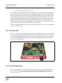
2.7.4 The Mezzanine board
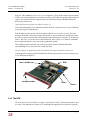
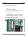
The mezzanine board is one physical implementation of the abstract RCE described above in
Section 2.7. It is a PCB board (100 mm x 80 mm) which hosts either one or two elements of RCE .
A mezzanine board plugs into any one of the five bays contained on a COB (see Sections 2.6.1
and 2.6.2).
Power (+6 VDC ) to this board is applied using two separate, but identical connectors. One
connector is assigned to each element of the board. Those connectors provide, in addition to
power, a presence sense pin as well as an enable pin for that power. The board’s two, internal
PDS (Power-Distribution-Systems) takes that input voltage, divides it down and distributes the
necessary, well regulated voltages to each element. Each PDS can source 25 Watts.
First release to reviewers
page 45