1
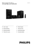
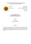
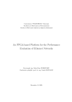
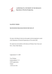
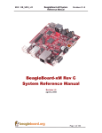
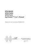
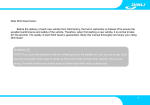
ATLAS Internal Note
December 15, 2004
ATL-TILECAL-2004-012
12/15/04
Standalone Software for TileCal ROD
Characterization and System Tests
J. Poveda, J. Castelo, V. Castillo, C. Cuenca, A. Ferrer,
E. Fullana, E. Higón, C. Iglesias, A. Munar, A. Ruiz-Martínez,
B. Salvachúa, C. Solans, J. Valls
IFIC
(CSIC – Universitat de València,
Dpt. de FAMN)
Valencia - SPAIN
Abstract
This note describes the programs XTestROD and XFILAR, developed for
the ATLAS TileCal ROD electrical characterization and system tests. All the
programs and GUI described here have been written in C and C++. These
programs allow to write/read the registers and configure the different
operation modes of all the modules in the ROD crate and the ROS computer.
Using this software standalone data acquisition runs can also be performed
through the VMEbus or the standard read-out cards in ATLAS.
1
INDEX
1
2
3
4
Introduction................................................................................................................... 4
Installation and Setup .................................................................................................... 4
Software Development .................................................................................................. 5
Using XTestROD.......................................................................................................... 7
4.1
The VMEbus Menu..............................................................................................9
4.2
The TTCvi Menu ...............................................................................................11
4.2.1
TTCvi L1A Trigger....................................................................................11
4.2.2
Bunch Crossing and Orbit Register ...........................................................11
4.2.3
Event/Orbit Counter Register.....................................................................11
4.2.4
B-Go Channels ...........................................................................................12
4.3
The ROD Final Menu ........................................................................................12
4.3.1
VME Controller .........................................................................................14
4.3.1.1 Local Register ........................................................................................14
4.3.1.2 IRQ Registers .........................................................................................14
4.3.2
Busy Registers............................................................................................15
4.3.2.1 Miscellaneous Register ..........................................................................15
4.3.2.2 Status Register........................................................................................17
4.3.2.3 Timing counters .....................................................................................17
4.3.3
Output Controller .......................................................................................17
4.3.3.1 Configuration Register ...........................................................................18
4.3.3.2 Status Register........................................................................................19
4.3.3.3 SDRAM Register ...................................................................................19
4.3.3.4 Dummy Register ....................................................................................20
4.3.3.5 Version Register.....................................................................................20
4.3.4
TTC Controller FPGA ...............................................................................20
4.3.4.1 Control Register .....................................................................................20
4.3.4.2 Status Register........................................................................................21
4.3.4.3 Dummy Register ....................................................................................21
4.3.4.4 Version Register.....................................................................................22
4.3.5
Staging FPGA ............................................................................................22
4.3.5.1 Configuration Registers .........................................................................22
4.3.5.2 RAM Data Transmission Registers .......................................................25
4.3.5.3 Link Configuration Registers.................................................................25
4.3.5.4 Status Register........................................................................................26
4.3.5.5 Temperature Registers ...........................................................................26
4.3.5.6 Dummy Register ....................................................................................26
4.3.5.7 Version Register.....................................................................................26
4.3.6
Dummy Processing Unit: FPGA PU..........................................................27
4.3.6.1 Data Format Registers............................................................................28
4.3.6.2 Configuration Register ...........................................................................30
4.3.6.3 Pulse and Set/Reset Busy Register ........................................................30
4.3.6.4 Status Register........................................................................................31
2
4.3.6.5 Read Internal FIFO ................................................................................31
4.3.6.6 G-Link counters .....................................................................................31
4.3.6.7 Dummy Register ....................................................................................31
4.3.6.8 Version Register.....................................................................................32
4.3.7
DSP PU ......................................................................................................32
4.3.7.1 DSP Booting submenu ...........................................................................33
4.3.7.2 Output FPGA submenu..........................................................................33
4.3.7.2.1 HPI Register .....................................................................................33
4.3.7.2.2 McBSP2 Serial Data Register..........................................................33
4.3.7.2.3 Control Register ...............................................................................33
4.3.7.2.4 Status Register..................................................................................35
4.3.7.2.5 Dummy Register ..............................................................................35
4.3.7.2.6 Version Register...............................................................................35
4.3.7.3 Input FPGA submenu.............................................................................35
4.3.7.3.1 Configuration/Status Register..........................................................35
4.3.7.3.2 Programming Register .....................................................................35
4.3.7.3.3 Version Register...............................................................................35
4.4
The DAQ Menu .................................................................................................36
4.4.1
Data Runs submenu ...................................................................................36
4.4.1.1 ROD Final PU – VME test mode ...........................................................37
4.4.1.2 ROD Final PU – S-Link test mode.........................................................38
4.4.2
Temperature Runs submenu ......................................................................38
5 Using XFILAR............................................................................................................ 40
5.1
The FILAR Menu...............................................................................................42
5.2
The DAQ Menu .................................................................................................43
Acknowledgements ........................................................................................................... 44
References ......................................................................................................................... 45
3
1 Introduction
The Read-Out Driver (ROD) is the intermediate link of the chain between the frontend electronics of the ATLAS Hadronic Tile Calorimeter (TileCal) and the general data
acquisition system of the ATLAS detector (TDAQ) [1].
Two different standalone Graphical User Interface (GUI) applications have been
developed for providing intuitive and easy to use tools to test and debug all aspects of the
ROD. These two applications are XTestROD and XFILAR.
XTestROD must be run in the ROD Crate Controller (RCC) and provides access
through the VMEbus to the ROD motherboard and the rest of the VME modules placed
in the crate (TTCvi, TTCpr, TBM, etc.). XFILAR must be run in the Read-Out System
(ROS) computer to manage the data acquisition cards (FILARs), which are connected to
the ROD through optical links.
Both programs use the same hardware and low level software libraries developed in
the framework of the TDAQ software for ATLAS. The programs XTestROD and
XFILAR, together with all the low level libraries developed for the ROD Final and ROD
Demonstrator prototypes, have been developed at IFIC-Valencia.
These applications are designed to be powerful tools for system tests and
standalone data acquisition software packages capable of taking data even in lo ng burn- in
runs, expected during production. They have been used to qualify pre-production ROD
hardware and firmware functionality and to debug the system, in dedicated laboratory
setups (in building 5 at CERN and at IFIC - Valencia) as well as in the 2004 Combined
Test Beam at CERN.
2 Installation and Setup
XTestROD and XFILAR are organized as standard CMT packages. These
packages have been compiled using version 3.2 of the gcc compiler and releases
01-00-00 of the ATLAS Dataflow and Online Software. XTestROD also uses the
following packages developed by the TileCal-Valencia group:
o
o
o
o
rod_demo_rcc
rod_demo_putius_rcc
bit3_rcc
TileVmeROD
The latest stable version of these packages can always be found in the TDAQ CVS
repository under the [atlasdaq]/detectors/Tile tree. Detailed information about the
software can be found in http://ific.uv.es/tical/rod_new/online_tdaq/index.html.
4
To download the software packages follow the steps described below:
•
•
Configure the following environment variables:
§
export CVSROOT=:ext:atdaq-sw.cern.ch:/atdaqcvs
§
export CVS_RSH=ssh
To retrieve version vXrYpZ of the package type:
cvs –co –r vXrYpZ –d PackageName/vXrYpZ detectors/Tile/PackageName
To compile the software, follow the steps described below:
•
Configure the environment variables needed for CMT, Dataflow and Online
Software configuration. The XTestROD_HOME and XFILAR_HOME
environment variables must also be defined to place the XTestROD and
XFILAR configuration files.
•
Go to the directory PackageName/vXrYpZ/cmt.
•
Type cmt config and source setup.csh for tcsh shell. This will create the
compilation and installation scripts and configure some CMT related
environment variables.
•
Type gmake && gmake install. This will compile and install the
PackageName package.
3 Software Development
XTestROD and XFILAR have been developed using the Glade interface builder
tool and the related C and C++ code files. Glade is a free program available for all Linux
distributions which allows the creation of user graphical interfaces in a visual way. Figure
1 shows the Glade program running and their components.
The main Glade components are the following:
•
Glade Main Window: it lists all of the windows and dialogs created in the
interface project. By double-clicking on an item in the list the corresponding
window or dialog is shown. Menu and toolbar commands enable the
developer to create new projects, load and save them and build the source
code files.
•
Widget Palette: it shows all the available widget for building the interface
(windows, dialogs, boxes, buttons, labels, radio buttons, check buttons, etc.).
To add new windows and dialogs to the interface, the developer simply selects
the icon in the Widget Palette. To add widgets to a window or dialog, the user
must select the widget in the palette and click on the position desired for it.
•
Property Editor: it allows the developer to change the properties of widgets,
such as the widget size or the label text. The Signals tab also allows the
5
developer to add signal handlers to widgets (for example, specify the function
to be called when a button is clicked).
•
Widget Tree: it shows all the widgets in the interface project and the
dependences between them.
Figure 1: XFILAR program development using Glade. From left to right, the Glade
Main Window, Property Editor, Widget Tree, Widget Palette and XFILAR interface
window can be seen.
Glade generates some files which can be edited and comp iled using a standard
compiler. XTestROD and XFILAR have been compiled as CMT package and its file
structure is shown in Figure 2. The cmt directory only contains the requirements file, with
all the setting for compilation and linking. In the src directory all the source files and its
corresponding headers are placed, either created by glade or by the developer. These files
are the following:
•
PackageName.glade: this is the Glade project file.
•
main.cpp: this is the main file for the program. It contains the code needed for
windows and dialogs creation and the default startup options.
•
support.cpp and support.h: these files are created by Glade and should not be
edited by the developer. They contain widget related functions.
6
•
interface.cpp and interface.h: these files are created by Glade and should not
be edited by the developer. All widgets and signal associated with them are
defined in these files.
•
callbacks.cpp and callbacks.h: these files are created by Glade and can be
edited by the developer at will. Here the developer can write the code
functions to be executed for the different widget signals.
•
PackageName_main.cpp and PackageName.h: these files were created by the
developer for convenience. They are auxiliary files containing functions used
during program execution.
•
PackageName_utils.cpp and PackageName_utils.h: these files were created by
the developer for convenience and contain some basic utilities used in the
package.
Figure 2: XTestROD and XFILAR CMT packages file structure.
4 Using XTestROD
XTestROD is a GUI application written in C and C++ which allows the user to
have access and configure all the ROD crate hardware cards used in TileCal for data
acquisition and ROD system tests. All the related registers of these boards can be read
and configured from XTestROD. At present, XTestROD may access the following
hardware:
§
ROD Final motherboard (production board).
§
ROD Demonstrator motherboard (prototype board).
§
TTCvi
§
TTCpr
§
TBM
§
VMEbus
7
The XTestROD ROD Demonstrator menu will not be described in this note as it
will not be used in further ROD developments. Note that in the final ATLAS setup, the
TTCvi will not be placed in the ROD crate, but in a separate 6U Trigger and Timing
Control (TTC) crate. However, this card is also placed in the ROD crate in laboratory test
setups.
Figure 3: XTestROD Main Window. Note the Hardware Status semaphores in the
upper part of the window (in this case only TTCvi and ROD Final are active).
Figure 4: XTestROD Set Options Window.
XTestROD must be run in the ROD Crate Controller (RCC) computer, which
provides access through the VMEbus to all the registers in the cards placed in the ROD
crate. This way the user can configure intuitively the modules. XTestROD supports two
different crate controllers: the VP-110 from Concurrent Technologies (the chosen by the
ATLAS collaboration) and the BIT 3 from SBS Technologies, used for tests.
8
shows a picture of the XTestROD Main Window. Note that the program
version number is displayed in the title bar. By selecting the Set Options menu from the
File menu in the menu bar the XTestROD Set Options Window (see Figure 4) appears.
From this menu the user must provide the default values used in XTestROD each time it
starts. The different settings accessible from the XTestROD Set Options Window are the
following:
Figure 3
•
Print command: the default print command.
•
Data Path: the directory where the data files taken using XTestROD will be
stored 1 .
•
InFPGA Boot File: the default boot file for the Input FPGA in the ROD DSPPU (see Section 4.3.7.1).
•
DSP Boot File: the default boot file for the DSP in the ROD DSP-PU (see
Section 4.3.7.1).
These settings can be changed at any time during the execution of XTestROD and
will be saved for future program sessions with the OK button. At the top of the Main
Window the Quit button terminates the program (this functionality is also implemented in
the Exit entry in the File menu in the menu bar). The Hardware Status panel shows the
access status for each module in the ROD crate (TTCvi, TTCpr, ROD, etc.) at any time.
The rest of the Main Window shows a notebook panel with different submenus associated
to the hardware mentioned above.
4.1 The VMEbus Menu
From the VMEbus menu, the user has read/write access to any address in the
VMEbus. A view of the panels for this menu is shown in Figure 5.
In order to have access to the VMEbus, the user has to specify the type of crate
controller to use (VP110 or BIT3), the VMEbus address, the memory window size and
the address modifier (A16, A24, A32). With the Access VME button, the VME bus is
opened. The status of the bus is always shown in the Bus Status entry.
Once the VMEbus is opened, the user has the possibility to read/write data (Data
entry label, in hexadecimal) into a specified offset in the bus from the Offset entry label
(in hexadecimal). The user must select the write/read mode to be Safe (which checks
whether VMEbus errors occur during the operation) or Fast (in this mode, VMEbus
errors are ignored, with the consequent increase in bus access speed). This is done from
the Write/Read Mode entry label. After a write/read operation, the mode used is displayed
in the Bus Status entry, as well as any eventual error detected. 2
1
Make sure the directory specified in the Data Path entry has writing permissions when using
XTestROD or XFILAR.
2
All the bus access in XTestROD will be performed in Safe mode by default unless no option is
provided.
9
Figure 5: XTestROD VMEbus menu.
Figure 6: XTestROD TTCvi menu.
10
4.2 The TTCvi Menu
The TTC-VMEbus Interface (TTC vi) module [2] is a 6U VME card which allows
programmable selection of the trigger source and synchronous signal timing relative to
the LHC machine orbit. The main function of the TTCvi is to select a trigger source from
either up to four Level 1 Accept (L1A) front panel (FP) test trigger inputs, an internal rate
programmable random trigger generator or triggers generated by a specific VME access.
In XTestROD, the TTCvi module is handled from the TTCvi menu (Figure 6),
where the user has access to the different TTCvi registers. XTestROD handles a single
TTCvi card as only one is needed for each ROD crate. At the top of the TTCvi menu
window the base VME address register of the module must be set. Once it is initialized
with the Access Hardware button, the TTCvi identifiers are automatically shown. The
user has the possibility to reset the card, read, write and dump to the screen all the TTCvi
registers, which are described in the following subsections.
With the Write All Registers and the Read All Registers buttons all registers are
written or read, respectively.
4.2.1
TTCvi L1A Trigger
The L1A Trigger register handles the L1A trigger generation in the L1A Generation
box (FP 0 to 3, VME or random) and the L1A random trigger rate in the L1A Random
Rate box (from 1 Hz to 100 kHz) in case random trigger is selected from the L1A
Generation. The user can also reset the L1A FIFO (L1A FIFO Reset button) and access to
the read-only L1A FIFO Empty Flag and L1A FIFO Full Flag.
From this menu one can also generate a single L1A when VME generation is
selected as the trigger source (Generate L1A button), enable and disable the trigger word
(Enable Trigger Word and Disable Trigger Word buttons) and get the trigger word
address, subaddress and external flag parameters (with the Get Trigger Word Param
button).
4.2.2
Bunch Crossing and Orbit Register
From this register one can set the source of the orbit generation with the Orbit
Generation radio buttons to be internal or coming from FP. The Bunch Crossing delay
(expressed in nanoseconds) can also be read (in the BC Delay entry).
4.2.3
Event/Orbit Counter Register
From this register, the user can select the counter register to be either the event or
orbit counter (Select Counter radio buttons ). The selected (event or orbit) value can also
be monitored in the Counter Value entry and the counter can be reset at any time with the
Reset Event/Orbit Counter button.
11
4.2.4
B-Go Channels
In the TTCvi, four VME-addressable FIFOs are provided which may be pre- loaded
with commands and data to be transmitted by B Channel cycles. There are thus a total of
four B channels. For each of the four channels, the actual transmission of the pre-loaded
information is initiated by a signal called B-Go, which can be generated either by writing
to VME or by an external signal applied to one of four front panel inputs. It is also
possible to start the cycle transmission as soon as the FIFO is not empty. Hence, from the
B-Go channels box register, the user can select the mode for the four B-Go channels in
the module.
The possible choices for the B-Go mode are FP Enable (enabling external B-Go
input), Synchronous (generating a synchronous cycle at the end of the inhibit signal),
Single (non repetitive cycles), FIFO (B-Go is generated as soon as the FIFO is not
empty) and Calibration Mode (only for channel 2).
4.3 The ROD Final Menu
The ROD Final motherboard (MB) is a 9U VME module [1] which can read up to 8
optical fibres from the TileCal front-end electronics (drawers). It has up to 4 mezzanine
cards, called Processing Units (PUs), to process the data online before sending it to the
Transition Module (TM) [3] installed at the back of the VME crate. Figure 7 shows a
scheme of the back-end electronics for TileCal.
Figure 7: Scheme of the ROD back-end electronics
The TileCal ROD has to read and process data from about 10000 channels every 10
µs (which is the expected ATLAS first level trigger latency) and it must be able to work
in real time. The data gathered from these channels is digitized in the Front-End Board
(FEB) electronics and transmitted to RODs with high-speed optical links. There are 256
12
digital optical links (1 per FEB electronics drawer) which the ROD should be able to
manage and process at a maximum level 1 trigger rate of 100 kHz. This data is then sent
to the ROS which is the next step in the ATLAS DAQ chain.
Reference [4] shows a detailed explanation of the low- level library used to access
and configure the ROD motherboard. This library is integrated in the TileVmeROD
package.
A view of the panels of the ROD Final menu is shown in Figure 8. In order to
access the ROD module, the user has to specify the slot number in the crate where the
card is placed and the type of crate controller to use (VP110 or BIT3). With the Access
Hardware button, the ROD is initialized and all registers of the different FPGA blocks
can then be accessed. There are specific buttons to read all the registers in the menu
(Read All Registers) and to write them (Write All Registers). From the ROD Final menu
the user may access to the different FPGA blocks of the ROD from a notebook subpanel.
Figure 8: XTestROD ROD Final VME Controller menu.
From the Processing Units Booting box panel the user can boot the PUs in the
ROD. From PU 1 up to PU 4 option menus the user selects the PU type placed in the
corresponding MB slot. The possible choices are Dummy PU (see Section 4.3.6), DSP
PU (see Section4.3.7) and Empty (no PU plugged). With the File selection entry buttons
the user selects the online software code files to load into the DSP PU Input FPGA
(InFPGA File button) and into the DSP (DSP File button). No code needs to be provided
for the dummy PU as no booting is needed for this device.
13
In case the DPS PU is selected, the selected software code is loaded and the PU is
booted by clicking on the Boot PUs button. Otherwise, in case the Dummy PU is selected
its presence is checked. The corresponding PU indicator turns green if these operations
have been successfully performed. More options for DPS PU booting can be found in the
DSP Booting submenu of the DSP PU menu (see Section 4.3.7.1).
4.3.1
VME Controller
The VME and Busy FPGA in the ROD MB is responsible for the VME interface
between the CPU and the ROD MB, as well as for handling the busy signals at the ROD
level3 [5]. The VME Controller submenu describes only the FPGA registers related with
the VME communication and is shown in Figure 8.
From this menu the user has access to the Local Register and the IRQ Registers of
the VME and Busy FPGA, described in the following subsections. From the Local
Register panel, a General Reset command can be sent to the ROD (all the programmable
devices will then be reset to their default values). The Force Busy signal, which is
activated during ROD initialization in order to avoid incoming triggers, can also be
deactivated from this box menu (Deactivate Force Busy button). Note that this line must
be deactivated in order to operate the ROD in a normal way. See Section 4.3.2 for more
details about busy signal handling in the ROD.
The values of the registers in this menu can always be dumped on the screen using
the corresponding Print buttons.
4.3.1.1 Local Register
From the Local Register panel, the base address of the ROD can be read and
written (in hexadecimal) and the Board ID can only be read (also in hexadecimal). The
Status Register word can also be read as a hexadecimal word. The content of this word
register is also shown in detail with bit information about the Force Busy signal state
(Force Busy On bit), the number of PUs ready (PU Ready bits), the Extern Data Bus bit
and the Quick Answer bit.
4.3.1.2 IRQ Registers
In the ROD there are 6 possible interruption (IRQ) outputs (IRQ1 to IRQ6) with 15
possible interrupt sources: the 8 DSPs, the 4 Output Controllers (OCs), 2 for the busy part
and 1 more in case the G-Link temperature exceeds a threshold. Each interrupt source is
stored in an Interrupt Request Register (IRR) and then transmitted to an Interrupt Service
Register (ISR), which generates the IRQ VME signal.
3
Only one FPGA in the ROD motherboard is responsible for the VME controller and the busy
registers. However, they have been split into two different menus in XTestROD, according to the
functionality instead of the physical device responsible for them.
14
With the Status Registers the state of the IRQ sources and outputs, as well as the
state of the IRRs and ISRs can be accessed by VME. With the Mask/Enable Register the
IRQ sources can be masked and the IRQ outputs enabled.
With the Reset IRQs button all the requested and pending IRQs are erased from the
IRRs and ISRs.
The IRQ registers are not implemented yet in XTestROD.
4.3.2
Busy Registers
In a ROD MB there are 8 busy input signals coming from the PUs (1 per DSP, with
2 DSPs per PU). These busy lines arise when the DSP is not able to accept incoming data,
either because it is processing previous data or due to an operation error of the device.
The busy lines may also be selected to come from VME (see Figure 10). The busy input
signals are logically “ORed” (Busy Or signal), with the possibility to be individually
masked. The Busy Out signal, if enabled, drives the busy out and is sent to the Trigger
and Busy Module (TBM) [6] through the P3 backplane of the crate and to a LED on the
ROD front panel.
After power the card on the Busy Out signal is forced in order to avoid incoming
triggers during the ROD initialisation. After startup the user must deactivate the Busy Out
line through the Deactivate Force Busy button in the VME Controller submenu (Section
4.3.1). A detailed description of the ROD busy logic can be found in reference [5].
The Busy Registers submenu from the ROD Final menu is shown in Figure 9. From
this menu the user can access to the Miscellaneous Register, the Status Register and other
busy related timing counters, described in the next subsections. Finally, a pair of buttons
in this menu allow the user to send by VME a busy signal (Send BUSY through VME
button) and an IRQ signal (Send IRQ through VME button) if the Busy source bit from
the Miscellaneous Register is selected to be VME (see below).
The values of the registers and counters in this menu can always be dumped on the
screen using the corresponding Print buttons.
4.3.2.1 Miscellaneous Register
The Miscellaneous Register can be written/read as a hexadecimal word or through
their individual bits according to their functionality. From this box panel the user can
configure the settings for the busy logic in the ROD. This busy operation mode can be
selected to be Manual or Normal. The Manual mode is the default after a general reset. In
this mode the Busy Out and IRQ signals are disabled (which allows the user to set all
registers to the desired values before normal operation). The Normal mode is the
operation mode for typical DAQ runs where the busy input signals come from the DSPs
in the PUs.
With the Busy source bit the user can select the busy source to be either the PUs or
VME (it selects thus the input to the busy OR operation, see Figure 10).
15
Figure 9: XTestROD ROD Final Busy Registers menu.
Figure 10: Busy scheme logic for the ROD.
16
With the Enable Busy and Enable IRQ check buttons the busy and IRQ ROD
functionalities can be enabled or disabled by writing into these bits. With the Mask Busy
check buttons the user may individually mask the DSPs in order to choose which of them
are taken as input to be ORed for the Busy Out signal.
4.3.2.2 Status Register
The Status Register word can be read (in hexadecimal) in this menu and its bit
content displayed. From this register, the busy input signal (Busy In) from all DSPs (no
matter whether they are masked or not), and the Busy Out (the logical sum of the busy
input signals coming from the unmasked DSPs) can be read. The FIFO Full and FIFO
Empty flags and the IRQ In and IRQ Out bits are also displayed.
4.3.2.3 Timing counters
Several timing counters can also be read from the Busy Registers submenu. The
unit of time in all these counters is chosen by the user in the Clock Divider entry (in
hexadecimal). The 40.08 MHz ATLAS clock is thus divided by 4 and by the Clock
Divider value.
The Duration Counter entry represents the time during which the ROD has been
busy. The value of this counter is written into a FIFO at fixed time intervals (which are
set with the Write FIFO Interval entry, in hexadecimal). This FIFO can be read at any
time, as well as its FIFO Empty and FIFO Full flags.
The Busy IRQ Counter shows the time that the ROD has been busy since the last
reset of the counter. If this value is larger than the Maximum count before IRQ entry (in
hexadecimal) an IRQ is sent. All the counters can always be reset either individually
(with specific buttons) or in a global way (Reset All Timing Counters button).
4.3.3
Output Controller
The OC FPGA of the ROD [7] is responsible for reading the event fragments from
the two output FIFOs associated to each DSP in the PUs. Hence there are four OCs in a
ROD motherboard, one per PU. The output data is sent either to a SDRAM memory (to
be read using a VME protocol) or to a serializer chip in the ROD motherboard. In this
case the data is sent to the ROS through four optical links, using four S-link Link Source
Cards (LSC) [8] in the TM, one per OC. The OC FPGA also formats the event including
a header and a trailer and manages the VME request, SDRAM and serializer chips.
The Output Controller submenu of the ROD Final menu is shown in Figure 11. In
this menu, after selecting which one of the 4 OCs in the ROD will be configured (Select
OC option menu), the user can access to the OC Version, Configuration, Status, SDRAM
and Dummy Registers.
The values of the registers and counters in this menu can always be dumped on the
screen using the corresponding Print buttons.
17
Figure 11: XTestROD ROD Final Output Controller menu.
Figure 12: Scheme of the OC working in Normal Mode (left) and in Staging Mode (right). Note the
different In/Out setting for the two OCs when working in Staging Mode.
4.3.3.1 Configuration Register
With the write/read Configuration Register the user can configure all the
parameters related with the output data transmitted with the ROD. The Configuration
Register word can be accessed as a hexadecimal word or by its bit functionality. By
writing into the Mask PU FIFO check buttons, the 2 FIFOs on the PU corresponding to
the selected OC can be masked. If the Enable S-Link check button is set, the data is sent
to the S-Link LSC through the TM. Otherwise, the data is stored in the SDRAM. The
18
Data Taking Mode (DTM) check button controls the data flow: when it is set, the data is
sent to the SDRAM or to the S-Link; otherwise no data is sent.
The user can select with the bankmax and rowmax bits the part of the SDRAM to
be filled with data 4 . When the Transfer All check button is deactivated, the word counting
and the End of Event word (0xE0E00000) are not transmitted. By setting the Enable Spy
bit, one event is stored in the SDRAM for VME read-out and monitoring purposes. See
Section 4.4.1 for a detailed description on the correct configuration of the OC bits for a
typical data acquisition run.
There is also the possibility with this register to set the OC to operate in Staging
Mode5 . In this case, the output data from one PU is sent to two OCs instead of one. To
configure the OC for working in Staging Mode, the Staging Mode check button must be
selected. In case the OC has to deal with data coming from its corresponding PU the
In/Out bit must be unset, and set if it has to deal to data coming from the other PU. This
bit has no effect if Staging Mode is not enabled.
For convenience, there are buttons in the panel for reading and writing all the bits
in this register.
4.3.3.2 Status Register
The read only Status Register contains information about the SDRAM and S-Link
status. This register word can be read as a hexadecimal word and its bit contents
functionality displayed. The Memory Size entry shows the number of words which are
stored in the SDRAM. The Memory Empty flag indicates that no words are stored in the
SDRAM. The Memory Full flag shows that the SDRAM has reached its maximum
capacity and the Memory Complete flag indicates that the selected capacity with the
bankmax/rowmax bits of the Configuration Register has been reached.
Other flags are automatically set when the S-Link fails to pass a test successfully
(Link Failure bit) and when no 0xE0E pattern appears in some event (EOE flag bit).
These last two flags can be reset independently with the Reset Link and Reset EOE Flag
buttons in the main Output Controller submenu. A global OC reset is also possible with
the Reset OC button.
4.3.3.3 SDRAM Register
With the SDRAM Register the user has access to the words stored in the SDRAM
memory. When the Data Available check button (in the Status Register) is enabled, by
reading this register the first word in the SDRAM is read (and removed from the
memory).
4
The SDRAM used in the OC has four banks of memory with 4096 rows each. Each row has a
capacity of 256 32-bit words. Hence each bank has a capacity of 4 KB. With these bits the user
selects up to which bank and row within this bank the SDRAM could be filled with data.
5
Note the difference between the Staging Mode in the OC FPGA and in the Staging FPGA,
explained in Section 4.3.5.
19
4.3.3.4 Dummy Register
This is a write/read register used for tests with no relevant information about the
status or configuration of the device.
4.3.3.5 Version Register
This is a read only register which contains the OC firmware version number (in
hexadecimal) where the first digit represents the version number and the last two the
revision number. For example, if the content of this register is 0x320, the firmware
version of the OC would be 3.20.
4.3.4
TTC Controller FPGA
The TTC FPGA [9] is responsible for providing the ROD with all the TTC signals
and information for the different trigger operation modes.
The TBM, placed in slot #5 in the ROD crate, receives the TTC signals from the
trigger system, does the optical to electrical conversion and distributes them to all the
ROD modules in the crate through the P3 crate backplane. This information is received
by the TTCrx chip [10] in the ROD and recovered by the TTC Controller FPGA, which
distributes it to all four PUs.
The TTC Controller submenu of the ROD Final menu is shown in Figure 13. Here,
the user can access to the write/read Version, Control and Dummy Registers and the read
only Status Register of the TTC FPGA, which are described in the following subsections.
The values of the different registers in this menu can always be dumped on the screen
using the corresponding Print buttons.
In addition, with several write only entries the user can provide the Bunch Crossing
ID, the Event ID, Trigger Type and the TType Sub-Address in a write/read entry when
working in VME mode (see below).
4.3.4.1 Control Register
The Control Register word may be accessed in hexadecimal format or by its bit
contents. With this register the trigger operation modes of the ROD can be selected with
the Trigger Mode radio button. The possible choices are the TTC mode (TTC signals
coming from the TTC system), the Local mode (TTC signals come now from a ROD
Injector module via an internal ROD connector) and the VME mode (all TTC signals are
generated by the VME interface).
In TTC mode, the clock source must be set to TTC Clock (the clock signal comes
from the TTCrx chip). In VME and Local modes the clock source must be MB Clock
(with a jumper in the motherboard this clock can be selected to be either a local clock
oscillator or a clock signal coming from the ROD Injector via a ROD internal connector).
From this register, the user can also select whether the ROD uses the so called
Double L1A Pulse Mode (where the L1A signal will last for two clock cycles instead of
20
one). From specific buttons, one can also reset the TTCrx chip (Reset TTCrx button),
reset the event counters in the Status register (Reset Event Counters button), clear the data
buffers in the acquisition cha in (Flush Buffers, only for VME trigger mode) and clear the
Status Register (Clear Status button).
Figure 13: XTestROD ROD Final TTC Controller menu.
4.3.4.2 Status Register
The Status Register of the TTC FPGA may be read as a hexadecimal word and its
bit contents displayed in the panel. From this register the user can check whether the
TTCrx chip is ready (TTCrx ready bit) and if the TTC clock is selected and present (TTC
Clock Selected and Present bit). There are also in this menu counters for the number of
errors in the single or double L1A pulse mode (Single L1A Pulse Mode: Errors and
Double L1A Pulse Mode: Errors entries), as well as how many times there has been a
non-double L1A trigger when operating in the double L1A pulse mode (Double L1A
Pulse Mode: Non double L1A entry).
4.3.4.3 Dummy Register
This is a write/read register used for tests with no relevant information about the
status or configuration of the device.
21
4.3.4.4 Version Register
This is a read only register which contains the TTC Controller firmware version
number, shown in hexadecimal, where the first digit represents the main version number
and the last three digits the revision number.
4.3.5
Staging FPGA
The Staging FPGA is responsible for receiving the incoming data into the ROD
from two different G-Link chips and route it to the PU. In Normal Mode operation, the
data from two G-Links is sent to a single PU. There is also the possibility to work in the
so called Staging Mode 6 , where the data coming from four G- Links is sent to a single PU
(using a bus between each pair of Staging FPGAs). Figure 14 shows a scheme of the
ROD operation in Staging Mode.
In addition, a special feature is provided for standalone tests of the ROD. The
Staging FPGA has a RAM memory where up to 1024 32-bit words can be stored. The
user can now configure the system in order to send this data to the PU, emulating the
transmission of events from the FEB.
The Staging FPGA submenu of the ROD Final menu is shown in Figure 15 and
Figure 16. From this menu, the user has access to all the VME configurable registers in
the FPGA. In the upper part of the panel the user selects which one of the four Staging
FPGAs in the ROD will be accessed with the Select Staging option menu. The version
number of the Staging FPGA firmware can be read and printed with the read only
Version Register. The other registers in the FPGA are accessed from two different
submenus : a Configuration submenu (Figure 15) and a Status submenu (Figure 16).
From the Configuration submenu, the user has access to the write/read Dummy
Register, the two Configuration Registers, the Link Configuration Register and the RAM
data transmission related registers. On the other hand, in the Staging FPGA Status
submenu, the read only Status Register and Temperature Register can be accessed.
The values of all the registers and counters in this menu can always be dumped on
the screen using the corresponding Print buttons.
4.3.5.1 Configuration Registers
From the Configuration Registers panel, the user can read/write the two
Configuration Registers (in hexadecimal) of the FPGA. The registers can be accessed as
a hexadecimal word or by its bit functionality.
6
Note the difference between the Staging Mode in the Staging FPGA and in the OC FPGA,
explained in Section 4.3.3.
22
Figure 14: Scheme of the ROD working in Staging Mode. Note how the output from Staging FPGAs #2
and #4 is sent to the Processing Unit corresponding to Staging FPGAs #1 and #3, respectively.
Figure 15: XTestROD ROD Final Staging FPGA menu: Configuration submenu.
23
Figure 16: XTestROD ROD Final Staging FPGA menu: Status submenu.
With these registers, the user can configure the Staging FPGA operation mode. As
mentioned before, the ROD can work either in Normal Mode (4 input channels are
processed by 2 PUs) or Staging Mode (4 input channels are processed by a single PU);
this can be chosen with the Staging Mode bit. When operating in Staging Mode, the
output from each Staging FPGA can be routed either to its corresponding PU or to the
near PU (see Figure 14). In the first case, the user should check the FEB1 and FEB2 bits
in the Enable Output entry, together with the Staging to own PU bit. This configuration is
the same when working in Normal Mode. On the contrary, if the Staging FPGA operating
in the Staging Mode has to be routed to the PU near its corresponding PU, the user must
select instead the FEB1S and FEB2S bits in the Enable Output entry and uncheck the
Staging to own PU bit.
In the ROD front panel there is one LED per input optical fiber. There are four
possible LED operation modes available in the ROD. The user can select one out of these
four modes from the LED Mode entry:
•
FEB Mode 1 (normal): the LED is on when an error in the data transmission
has occurred (FEB Error, see Section 4.3.5.4). Otherwise, the data link is ready
(FEB Link Ready, see Section 4.3.5.4)
•
FEB Mode 2: in this mode the LED is on when a Start of Event word is
received. This will only be visible with data rates up to 100 Hz.
24
•
RAM Mode: in this mode, the two LEDs associated to the two links of each
Staging FPGA indicate when an event is sent from the RAM to the PU (top
LED) and when the infinite loop is activated (bottom LED).
•
Counter Mode: if events with consecutive words are injected into the ROD, the
LEDs operating in this mode indicate when a non consecutive word is received.
The user can also select here whether the FPGA manages incoming FEB data (FEB
Data radio button) or sends data from the RAM (DATA RAM radio button). The user can
also enable or disable input data from the G-Links to the FPGA with the Disable Input
bit.
Finally, the PU not ready bit is related with the PU Ready bit in the Local Register
of the VME Controller menu (see Section 4.3.1.1).
4.3.5.2 RAM Data Transmission Registers
The user can select from the Send Events from RAM menu box of the Staging
FPGA Configuration panel the number of events to be sent to the PU (Nb of events to
send entry) or to send them continuously through an infinite loop (Infinite loop check
button). The number of words per event can also be set (Nb of words per event entry) as
well as the delay between events in the Delay between events entry (in steps of 25 ns).
There is also the possibility to duplicate the data in order to emulate the transmission
from two input FEB channels by activating the Control Word check buttons for both
FEBs. These control words are needed for the transmission at the PU level. By activating
the Enable Busy from DSPs bit, the transmission is stopped when the PU FIFO is full.
From the Configuration panel, the user can also start the transmission of data from
the RAM (Start Transmission Data From RAM button), write and read the available data
in the RAM (Data to RAM register) and set the address where the first word of the event
has to be read (Start Address register).
4.3.5.3 Link Configuration Registers
The write/read Link Configuration register must not be edited by the user, as it may
have critical consequences for the ROD performance. The default values after a General
Reset (issued from the Local Register panel in the VME Controller menu) are those to be
used for normal operation of the ROD and data taking.
However, the value of this register can be read/write either as a hexadecimal word
or by its bit contents with the corresponding check buttons. The DIV0 and DIV1 entries
are used to program the clock divider chain. The FEB 1 Equal and FEB2 Equal bits must
be set to 1 if lemo cables are connected to the ROD and to 0 if optical fibers are instead
used. The FEB 1 Flag and FEB2 Flag bits must always be set to 1.
25
4.3.5.4 Status Register
The read only Status Register can be accessed as a hexadecimal word. Its value is
shown in the corresponding entry and its bit contents displayed in the panel. The CAV
entry lines (Control Available Output) indicate whether the FPGA is receiving data or
not, and are used to frame the data. The DAV entry lines (Data Available Output ) indicate
whether the chip has received data frames. Both entry lines can be read for either FEB 1
or FEB 2. The FEB1 and FEB2 Link Ready signals indicate whether the fibers coming
from the drawer are connected with a good communication between them and the ROD.
The FEB1 and FEB2 Error signals indicate if an error in the data transmission has
occurred. There are also counters for the number of times the FEB Error signal has
happened. In addition, there are Internal FIFOs Real Time and Latched Flags entries for
the Empty/Full state of the two internal FIFOs defined in the Staging FPGA.
4.3.5.5 Temperature Registers
One of the most critical points of the G- link performance is its temperature [11].
For the TileCal ROD it must not exceed 75°C due to chip specifications. A set of
Siemens B57702-M103-G thermistors are placed close to each G- link chip and used to
monitor their temperature. The temperature values are read-out by one multichannel
MAX1110 ADC, which has eight analog inputs and a serial 8-bit digital output. The
output is connected to the staging FPGA number three of the ROD where the current
temperature for each G- link chip as well as the minimum and the maximum temperature
achieved by each chip since the last reset are stored.
From the Temperature Register menu box the temperature from all eight G-Links
can be monitored. The user has to specify the G-Link whose temperature is desired to
read in the G-Link Number entry. By clicking on the Read button the corresponding
register is read (in hexadecimal) and the Current, Maximum and Minimum temperatures
(in Celsius) are displayed in the corresponding entries. The value of the Maximum and
Minimum temperatures can always be reset with the Reset button.
4.3.5.6 Dummy Register
This is a write/read register used for tests with no relevant information about the
status or configuration of the device.
4.3.5.7 Version Register
This is a read only register which contains the Staging FPGA firmware version
number in hexadecimal where the first digit corresponds to the version number and the
last three digits to the revision number.
26
4.3.6
Dummy Processing Unit: FPGA PU
The dummy Processing Unit (or FPGA PU) of the final prototype ROD [1] is a
simple board designed to test the ROD in absence of final DSP PU and exploit the FPGA
features. There are up to four FPGA PU daughter boards per ROD. It is equipped with
two 8 kBytes IDT72V253 FIFOs (the same used for the final DSP PU) and an
APEX20KE FPGA, as seen in Figure 17. With this device one can test if the motherboard
is able to send data correctly to the PU and if the OC is able to read data from the two
FIFOs. Furthermore, DAQ runs can be taken using this dummy PU, although no online
energy reconstruction is possible as there are no DSP processors in this device.
The FPGA PU submenu of the ROD Final menu in XTestROD is shown in Figure
18 and Figure 19. From this menu the user has access to all VME registers of the FPGA.
The user has to select which one of the 4 FPGA PUs in the ROD will be accessed
from the Select PU option menu. The FPGA PU menu is divided in two different
submenus, each one related with the Configuration (Figure 18) and the Status (Figure 19)
FPGA PU registers.
From the Configuration submenu, the write/read Pulse and Set/Reset Busy,
Configuration and ROD Output Data Format registers can be accessed. From these
registers the user can customize the output data format coming out from the ROD.
From the Status submenu, the read only Status Register, Read Internal FIFO
Register, G-Link Counters and Event Counters can be accessed. From this submenu the
user can also have access to the write/read Dummy Register.
Figure 17: ROD dummy Processing Unit (or FPGA PU). The devices which form the dummy PU are
shown on blue and the LEDs and their functionality in Normal Mode are shown in red.
27
Additionally in the main FPGA PU menu a read only Version Register and specific
buttons to reset the internal and the external FIFOs (Reset Int FIFO and Reset Ext FIFO
buttons, respectively), the G-Links (Reset G-Link 1 Stag, Reset G-Link 2 Stag, Reset GLink 1 and Reset G-Link 2 buttons) and the Latched Flags (Reset Latched Flags button)
are provided.
The values of the registers and counters in this menu can always be dumped on the
screen using the corresponding Print buttons.
4.3.6.1 Data Format Registers
The ROD Output Data Format registers provide the words which form the header
for the two data fragments coming from each G-Link. For a detailed description of the
data format see reference [12]. The header words which can be customized are the
following:
•
Format Version Number: a 32-bit integer number which defines the version
number of the ROD data fragment header.
•
Source ID for either FEB1 or FEB2 : words which identify the source of the
fragments. They consist of a subdetector ID, Module Type and Module ID.
•
Run Number: a 32-bit integer number which identifies the data run number.
•
Extended Level 1 ID: a 32-bit word for the L1ID (Level 1 Trigger ID
generated in the TTCrx in ATLAS) identifier (24 lower bits) and the ECR
(Event Count Reset, 8 upper bits). This ECR signal resets the 24-bit L1A and
increments the 8-bits ECR counter.
•
Bunch Crossing ID (BCID): a 12-bit bunch crossing identifier word, generated
by the level 1 trigger system in ATLAS.
•
Level 1 Trigger Type: an 8-bit word which contains the information sent by
the level 1 trigger system about the event type. It is generated by the Central
Trigger Processor (CTP) in ATLAS.
•
Detector Event Type: identifies the type of the event, which can be either a
physics event (if set to 1), a pedestal event (if set to 4), a calibration event
from the Charge Injection System (CIS) (if set to 8) or a laser event (if set to
2).
•
Number of Words per Event: number of words in each fragment.
•
Sub-Fragment ID for either FEB1 or FEB2 : 32-bit words which identify each
of the sub- fragments associated to each event.
28
Figure 18: XTestROD ROD Final FPGA PU menu: Configuration submenu.
Figure 19: XTestROD ROD Final FPGA PU menu: Status submenu.
29
4.3.6.2 Configuration Register
From the Configuration Register panel the user can read/write the Configuration
Register as a hexadecimal word or access it through its bit functionality.
From this register the user can enable or disable the headers of the data coming
from each G-Link (Enable PU Header for G-Link/FIFO 1 and 2 check buttons). The
format of the headers can be chosen between the following data header format modes:
•
BCID, TType and Evt ID from VME : the header words for all events are taken
from the values provided in the ROD Output Data Format panel, including the
BCID, TType and Event ID.
•
BCID, TType and Evt ID from TTC FPGA: in this mode the BCID, TType and
Event ID words are taken from the TTC FPGA, while the rest from the values
provided in the ROD Output Data Format panel.
•
BCID from FEB, Evt ID incremented from initial VME value: in this mode the
Event ID is incremented event by event from an initial value provided by the
user in the ROD Output Data Format panel. The BCID is taken from the FEB
and the rest of the header words from the ROD Output Data Format registers.
•
BCID from VME, Evt ID incremented from initial VME value: in this mode
the Event ID is also incremented event by event from an initial value provided
by the user in the ROD Output Data Format panel. The rest of the header
words (including the BCID) are taken from the ROD Output Data Format
registers.
From the Configuration Register the user can also set the Busy Pulse Length (in
units of 25 ns) of the pulse busy signal sent from the PU for test purposes. The dummy
PU LED mode can also be selected to be:
•
Info displayed in LEDs: the LEDs display information about the Start of Event
and the Busy and FIFO state of the two FIFOs in the PU (see Figure 17).
•
LEDs in “Knight Rider”: the LEDs display just a flashy side-to-side light
(used only for tests).
There is also the possibility to specify in the FEB input entry whether the FEB
input going into the PU FIFO is coming from its corresponding Staging FPGA (FEB 1-2
-> FIFO 1-2 radio button) or from it near Staging FPGA (FEB 1-2 S -> FIFO 1-2 radio
button).
4.3.6.3 Pulse and Set/Reset Busy Register
With the Pulse and Set/Reset Busy register the user may send an interruption (IRQ
1 and IRQ 2 bits) or a busy signal for debugging purposes. From the Busy 1 and Busy 2
bits, the corresponding FIFO is set to be in busy state. From the Pulse Busy 1 and Pulse
Busy 2 bits, the busy signal is send as a pulse with a length specified in the Busy Pulse
Length entry of the Configuration Register.
30
4.3.6.4 Status Register
The read only Status Register can be accessed as a hexadecimal word and its bit
contents displayed in the corresponding entries. From this register the user can read
whether the PU is working in Staging Mode (Read Staging bit) and access to the Busy
and Full/Empty FIFO states of the PU through the Real Time Flags and Latched Flags
bits described below.
The Real Time Flags indicate the state of the Busy and FIFOs at the moment the
Status Register is read. The Latched Flags indicate whether this state has been reached
since the last reset of the ROD (a Latched Flag bit on means that at some instant since the
last reset the Real Time flag has been on).
There are Real Time Flags and Latched Flags for the External FIFOs Busy signals
and the FIFO Empty/Full states. There are also flags for the Almost Full/Empty state,
which indicates a FIFO 7 memory usage less than 1024 16-bit words for the Almost Empty
Flag and more than the total size minus 1024 16-bit words for the Almost Full Flag. By
using the Almost Full Flag as a busy signal instead of the Full Flag, a missing event due
to lack of memory space in the FIFO is prevented.
For the internal FIFOs in the FPGA there are Real Time Flags for the FIFO
Empty/Full states also accessible from this register.
4.3.6.5 Read Internal FIFO
From this panel the user can read the contents of the two internal FIFOs in the
FPGA PU (see Figure 17). Each FIFO contains 16-bit words although the contents of
both FIFOs are actually displayed as a single 32-bit word.
4.3.6.6 G-Link counters
From this panel the user can read the counters for the number of errors produced in
the G-Links data reception. The Link ready entry displays the number of rising edges
found in the Link-Ready signal. This signal, sent from the G-Links, indicates that the
startup sequence is complete and that data and control indications are valid. Any change
in this signal after startup would lead to errors in data reception. The Link errors entry
displays the number of times an error has been found in the data, at least in the C-field.
4.3.6.7 Dummy Register
This is a write/read register used for tests purposes with no relevant information
about the status or configuration of the device.
7
The specifications for the Almost Full and Almost Empty states are valid for the FIFO IDT72V253, used
in the FPGA PU.
31
4.3.6.8 Version Register
This is a read only register which contains the OC firmware version number (in
hexadecimal) where the first digit represents the version number while the last two digits
the revision number.
4.3.7
DSP PU
The DSP PU [13] is a more complex device than the dummy PU as it performs
digital signal reconstruction. It calculates precisely the energy deposit in the calorimeter
cell and the timing of these signals. Moreover it performs monitoring tasks and formats
the data for the next element in the electronic chain.
The DSP PU is composed of two blocks, each one with an input FPGA Cyclone
EP1C6, a TMS320C6414 DSP from Texas Instruments and an external output FIFO. The
DSP PU also contains an output FPGA Cyclone EP1C6 used for the VME and TTC
interface. Figure 20 shows a picture of the DSP PU. The input FPGAs and the DSPs can
be programmed via VME by uploading the corresponding code through the VME
interface.
Figure 20: Picture of the ROD DSP PU.
The DSP PU submenu of the ROD Final menu in XTestROD is shown in Figure
21, Figure 22 and Figure 23. From this menu the user can boot the DSP PU and have
access to all its VME configurable registers.
The user has to select which one of the 4 DSP PUs in the ROD will be accessed
from the Select DSP PU option menu. The DSP PU menu is divided in three different
submenus : DSP Booting (Figure 21), Output FPGA (Figure 22) and Input FPGA (Figure
23).
32
From the Output FPGA submenu, the read only Version and Status registers, the
write/read Control, McBSP2 Serial Data and HPI registers can be accessed.
From the Input FPGA submenu, the read only Version Register, the write/read
Configuration/Status Register and the write only Programming Register can be accessed.
4.3.7.1 DSP Booting submenu
From this menu the user can select the code files to load into the input FPGA and
into the DSP. Here the booting of the DSP PU may also be started. The files containing
the software code to be loaded can be selected with the File Selection buttons (InFPGA
File button for the input FPGA file and DSP File button for the DSP file). The selected
files are displayed in the Selected File labels.
The user can boot separately each of the two blocks which compose the DSP PU or
both blocks with the DSPs to Boot radio buttons. By clicking the BOOT DSP PU button
the selected DSPs and input FPGAs are booted with the corresponding files.
4.3.7.2 Output FPGA submenu
The user must specify whic h one of the two output FPGAs in the DSP PU will be
accessed from the Select OutFPGA option menu. The bit writing operations can be
performed in broadcast mode (i.e., write the same bit in both output FPGAs) by activating
the Write Broadcast radio button. From this menu the have access to the following
registers:
4.3.7.2.1 HPI Register
The Host Port Interface (HPI) is a 16-bit wide bus connected between the DSP and
the output FPGA through which the VME can directly access the DSP memory space. It
is mainly used for DSP booting, histogram reading and debugging purposes. From the
write/read HPI Register entry the user can read data from the DSP or write data into the
DSP while it is running.
4.3.7.2.2 McBSP2 Serial Data Register
The Multichannel Buffered Serial port 2 (McBSP2) si a bidirectional serial port
which connects the output FPGA and both DSPs. The write/read McBSP2 Serial Data
Register is used to exchange data between these devices (send commands to the DSP,
read the DSP status, etc.).
4.3.7.2.3 Control Register
The write/read Control Register word may be accessed in hexadecimal format or by
its bit contents. From this register the user can reset the DSP (DSP Reset bit) the HPI
(HPI Reset bit), the input FPGA (Input FPGA Reset bit) and the corresponding FIFO
(FIFO Reset bit). Moreover the user can access to the DSP Launch, HPI Burst and Input
FPGA not Config bits.
33
Figure 21: XTestROD ROD Final DSP PU menu: DSP Booting submenu.
Figure 22: XTestROD ROD Final DSP PU menu: Output FPGA submenu.
34
4.3.7.2.4 Status Register
The read only Status Register can be accessed as a hexadecimal word. Its value is
shown in the corresponding entry and its bit contents displayed in the panel. This register
contains information about the number of events contained in the McBSO2 FIFO (Nb
Events McBSP2 FIFO entry) and in the output FIFO (Nb Events Output FIFO entry), as
well as their Empty/Full flags (Output FIFO Flags and McBSO2 FIFO Flag entries). The
user can also read in this register the value of the GP11, GP12 and GP13 bits, as well as
the HPI INT, HPI Ready, InFPGA Nstatus and InFPGA ConfDone bits.
4.3.7.2.5 Dummy Register
This is a write/read register used for tests with no relevant information about the
status or configuration of the device.
4.3.7.2.6 Version Register
This is a read only register which contains the DSP PU output FPGA firmware
version number in hexadecimal where the first digit corresponds to the version number
and the last digits to the revision number.
4.3.7.3 Input FPGA submenu
The user must specify which one of the two input FPGAs in the DSP PU will be
accessed from the Select InFPGA option menu. The bit writing operations can be
performed in broadcast mode (i.e., write the same bit in both output FPGAs) by activating
the Write Broadcast radio button. From this menu one has access to the following
registers:
4.3.7.3.1 Configuration/Status Register
The write/read Configuration/Status Register word may be accessed in
hexadecimal format or by its bit contents. From this register the user can configure the
number of gains and samples used (Nb of Gains and Nb of Samples entries, respectively)
and the chunk size (size of Chunks entry).
4.3.7.3.2 Programming Register
The write only Programming Register allows the programming of the input FPGA
at any time directly from the VME interface, without using any software code files.
4.3.7.3.3 Version Register
This is a read only register which contains the DSP PU input FPGA firmware
version number in hexadecimal where the first digit corresponds to the version number
and the last digits to the revision number.
35
Figure 23: XTestROD ROD Final DSP PU menu: Input FPGA submenu.
4.4 The DAQ Menu
From the XTestROD DAQ menu (see Figure 24) the user can start data acquisition
runs with different settings. The DAQ menu is divided in two submenus : Data Runs and
Temperature Runs submenus. From the Data Runs submenu the user can take data
coming from real TileCal drawers or from custom data injector VME modules (ROD
Injector boards). From the Temperature Runs submenu the temperature from the 8 GLinks can be recorded for monitoring purposes.
4.4.1
Data Runs submenu
The Data Runs submenu contains the ROD Selection and Configuration panel and
a tab menu with the ROD Final Counters and ROD Demo Counters.
From the ROD Selection and Configuration panel the user can select which board
to be used for data taking (ROD Demo or ROD Final) and the trigger/output
configuration. The trigger sources for the ROD can be selected to be VME, TBM and
from a front panel (FP). The ROD Final allows also an internal trigger generation in the
PU. The selected output data can be:
•
VME: the data is read from the SDRAM in the OC as shown in Section 4.3.3.3
•
S-Link: the data is sent through the HOLA Link Source Cards (LSC) in the TM
to the FILAR PCI cards in the ROS computer.
36
Only the VME – VME and VME – S-Link modes are implemented for the ROD
Demo prototype and the PU – VME and PU – S-Link for the ROD Final.
From the ROD Final Counters and ROD Demo Counters the data acquisition run
settings can be configured and the event counters can be read. If ROD Final PU – VME
or PU – S-Link modes are selected the user sets which OCs and which of its two FIFOs
are enabled for data taking in the Enabled OCs for Test Modes box (of the ROD Final
Counters tab menu).
Once all the desired options are selected the user may start an acquisition run by
clicking on the Start button. With the Stop button the user can stop the run at any time.
The ROD comes back then to its initial state and all the data files are closed.
Figure 24: XTestROD DAQ menu: Data Runs submenu.
4.4.1.1 ROD Final PU – VME test mode
When the PU - VME ROD Final configuration is chosen, the user has to select in
the OC counters for PU – VME Mode panel the output data format from the Output file
format radio buttons, the counters refreshing mode (Auto or Manual), the VME
Write/Read mode and the number of Words to store.
From the Output file format radio buttons the user selects to store data on disk in
ASCII or binary format, to dump the data on the console (Dump on Screen option) or not
to record data to disk (No Data Logging option).
37
The event counters for all OCs can be refreshed automatically during the run by
activating the Refresh Auto option or manually with the Refresh OC Counters if the
Refresh Manual option is activated. The automatic counter refreshing mode is not
recommended for medium and high data rates.
The user can also select the VME Write/Read mode to be Save or Fast (see Section
4.1) and the number of words to be stored in the SDRAM (Words to store entry) before
starting the run. The number of words in the SDRAM can be read with the Memory Size
entry in the Status Register panel (Output Controller menu). Once the provided value is
achieved, all the words in the SDRAM are read using the SDRAM Register in the Output
Controller menu.
When the acquisition run starts, the busy logic of the ROD is automatically
configured to deactivate the Force Busy signal (VME Controller menu Local Register
panel), to set the PU as Busy source, to unmask the selected FIFOs (Mask Busy entry)
and to activate the Enable Busy bit (all in the Busy Registers menu Miscellaneous
Register panel).
4.4.1.2 ROD Final PU – S-Link test mode
In this mode, the ROD is configured to send the output data to the FILAR card
through the S-Link HOLA cards in the TM. This is done by unmasking the selected
FIFOs and activating the Data Taking Mode, Enable S-Link and Transfer All bits for the
enabled OCs in the Output Controller menu Configuration Register submenu.
These data can be read and saved to disk in the ROS computer using the XFILAR
program (see Section 5).
When the acquisition run starts, the busy logic of the ROD is automatically
configured to deactivate the Force Busy signal (VME Controller menu Local Register
panel), to set the PU as Busy source, to unmask the selected FIFOs (Mask Busy entry)
and to activate the Enable Busy bit (all in the Busy Registers menu Miscellaneous
Register panel).
4.4.2
Temperature Runs submenu
As shown in Section 4.3.5.5, the G-Link temperature is a critical point in the ROD
performance. In consequence, XTestROD has the possibility to take and record G-Links
temperature data in dedicated runs. The values of the G-Link temperature are obtained by
reading the Staging FPGA menu Temperature Register.
Once the run is started (by clicking the Start button) a series of consecutive G-Link
current temperature measurements are made after a time period (set with the Time
Interval entry) elapses. The amount of measurements made is set by the user in the #
events to average entry. XTestROD calculates the mean and its RMS for all the se
measurements (in ADC counts) and store them in an output binary file. After a series of
measurements finishes, the mean value for the temperature of all G- Links is displayed in
the Last Reading Temperature Values entries. The next series of measurements will start
after the time set in the Time Interval entry has again elapsed.
38
Figure 25: XTestROD DAQ menu: Temperature Runs submenu.
Figure 26: Format for the Temperature run output file.
The output binary file format is displayed in Figure 26. There are 20 float words
per record. It contains a header and a trailer word to frame the events, the value of the
time since the beginning of the run when the recording was made, the number of events
39
to average (for completion), and the mean and RMS values of the current temperature (in
ADC counts).
Two special cases must be considered:
•
When the # events to average entry is set to 1 the calculation of the RMS is
senseless and a -1 value is saved in the output file.
•
When the Time Interval entry is set to 0, a single series of measurements is
performed during the run. The values of all measurements are stored in the
output file without averaging. The total number of measurements is set in the #
events to average entry and a -1 RMS value is saved in the output file.
Note that during the run the name of the output data file, the number of points
recorded and the elapsed time during the last series of measurements are always
displayed on the screen.
5 Using XFILAR
The FILAR (Four Input Links for Atlas Read-out) [14] is a highly integrated PCI
interface card which can move data from up to four HOLA (High-speed Optical Link for
Atlas) S-Link channels to a 32-bit or 64-bit PCI bus running at 33 MHz or 66 MHz. All
channels are fully compatible with the HOLA LSC [7] placed at the ROD TM boards.
They can receive data at a speed of up to 160 MB/s. The FILAR PCI interface is based on
the design of the old S32PCI64 interface.
XFILAR is a standalone GUI application to be run in the ROS computer (where the
FILAR cards are installed). The data send from the ROD to the LSC in the TM is
received by the Link Destination Channels (LDC) [13] integrated in the FILAR card via
optical links. XFILAR controls the FILAR cards in the ROS computer and allows the
user to read the data transmitted from the ROD motherboard.
Figure 27 shows a picture of the XFILAR Main Window. From this window the
user has access to two different submenu panels, the FILAR menu and the DAQ menu,
described below. By selecting Set Options from the File menu in the menu bar, the
XFILAR Set Options Window (see Figure 28) appears. From this window the user must
provide the default values used in XFILAR each time it starts. The different settings
accessible from the Set Options Window are:
•
Print Command: the default print command.
•
Data Path: the directory where the data files taken using XFILAR will be
stored 8 .
8
See footnote #1.
40
Figure 27: XFILAR main window with the FILAR menu.
Figure 28: XFILAR Set Options menu.
From the DAQ Options in the File menu bar, the DAQ Options window shows up,
shown in Figure 29 (this window can also be opened from the Open Run Parameters
Window button in the Main Window DAQ panel). Here the user must select the settings
related to the data acquisition runs. These parameters are:
•
Data Output: the user can select either not to save data to disk (No Data
Logging radio button), to dump events on the screen (Dump on Screen radio
button) or to save them in a binary or ASCII file (Binary File and ASCII File
radio buttons, respectively). The files are created in the path defined in the Set
Options dialog with an automatic name which indicates the date and time when
the run started.
•
Maximum Number of Events per Channel: set the maximum number of events
to be stored per channel. Once this limit is achieved, the DAQ run is stopped
automatically. By setting the Infinite loop check button an infinite DAQ loop is
instead selected and the run can only be stopped manually by the user.
•
Refresh Counters: select whether the event and error counters are refreshed
either manually or automatically when a new event arrives (not recommended
for medium and high rates).
41
•
Check Data Online: if this option is activated, an online checking is performed
on the data. This option is meant for checking the correct data transmission from
the ROD Injector cards. If some event containing errors is found, a counter is
incremented and the error event and the previous one are written to an ASCII
file for a more detailed check.
Note that these DAQ settings can always be changed at any time during the
execution of XFILAR.
At the top of the Main Window, the Quit button exits the program (as with the Exit
entry in the File menu) and the Hardware Status entry indicates whether the FILAR cards
are being accessed.
Figure 29: XFILAR DAQ Options dialog bo x.
5.1 The FILAR Menu
From the FILAR menu (Figure 27) the user may select which FILAR cards will be
accessed (up to a maximum of four cards corresponding to a single ROS computer) and
which channels of these cards will be enabled (up to four channels per FILAR card).
With the Access Hardware button, all the selected cards are initialized and the
selected channels enabled. The page size configuration of the selected FIALR cards (from
256 bytes up to 4 Mbytes) can be set from the Page Size option menu.
The user can always reset at any time any of the FILAR cards (Reset Card buttons)
and dump the FILAR info rmation parameters to the console through the Print FILAR Info
on Screen button.
42
5.2 The DAQ Menu
From the DAQ menu (Figure 30) the user starts/stops the data acquisition run
according to the settings defined in the DAQ Options dialog window (Figure 29). Once
defined the desired parameters for the acquisition, the user starts the run by clicking the
Start button. The selected parameters, the number of enabled channels and the event
counters are shown in the window (see Figure 30). The Refresh Counters button updates
the event counters for the enabled channels.
The DAQ run is stopped when the maximum number of events is achieved or
manually at any time with the Stop button.
Figure 30: XFILAR DAQ menu.
43
Acknowledgements
The authors would like to thank Markus Joos for his help with the FILAR and
Crate Controller hardware and software, Oleg Solov’yanov for all his help with the
Dataflow, Online Software and the CVS repository and Andrei Kazarov for his help with
CMT.
Joaquín Poveda would specially like to thank Juan Valls, José Castelo, Belén
Salvachúa and the rest of the TileCal-Valencia group for their help with this document
and during the software development procedure.
44
References
[1]
Tile Calorimeter Read Out Driver. Firmware Developments for the Final Prototype.
J. Castelo. September 2004.
Proceedings of LECC 2004.
Hardware requirements for TiCal ROD.
J. Castelo et al., December 2004.
ATLAS Note in preparation.
The ROD Mother Board for the ATLAS Liquid Argon Calorimeter.
A. Blondel, D. La Marra, A. Léger, I. Riu, A. Straessner. June 2004.
ATLAS EDMS document ATL-AL-EN-0055.
[2] TTC-VMEbus INTERFACE TTCvi – MkII.
Ph. Farthouat, P. Gällnö. May 2000.
Rev 1.6, RD12 project, CERN.
ATLAS EDMS document 110746.
TTCvi Library for ROD Crate DAQ.
R. Spiwoks. February 2003.
ATLAS EDMS document ATL-D-ES-0012 .
[3] A 9U Transition Module for the ROD Demonstrator.
P. Matricon. June 2004.
ATLAS EDMS document ATL-AL-EN-0053.
[4]
TileCal ROD Motherboard Software Library - User's Manual.
B. Salvachúa. October 2004.
Master Thesis unpublished. ATLAS Note in preparation.
[5]
VME and BUSY FPGA for the ROD motherboard.
A. Blondel, D. La Marra, A. Léger, I. Riu, A. Straessner. December 2003.
ATLAS EDMS document ATL-AL-EN-0060.
[6]
The Trigger and Busy Module of the ATLAS LARG ROD System.
P. Matricon. June 2004.
ATLAS EDMS document ATL-AL-EN-0054.
[7]
OC (Output Controller) FPGA of the LArgROD board Description.
D. La Marra. April 2004.
ATLAS EDMS document ATL-AL-EN-0056.
[8]
HOLA High-speed Optical Link for ATLAS.
A. Ruiz, E. van der Bij, June 2002.
ATLAS EDMS document 330901.
45
[9]
TTC FPGA Version 2.00.
G.Perrot / F. Corageoud. September 2003.
http://dpnc.unige.ch/LArgROD/TTC_FPGA2_00.pdf.
TTC System Implementation for ATLAS Liquid Argon Detectors.
Laforge, B; Perrot, G. April 2004.
ATL-ELEC-2004-003.
[10] TTCrx reference Manual.
J. Christiansen, A. Marchioro, P. Moreira and T. Toifl. January 2003
http://ttc.web.cern.ch/TTC/TTCrx_manual3.8.pdf.
[11] A. Ruiz-Martínez, A. Munar et al.
ATLAS Note in preparation.
The ATLAS LARG ROD G- Links Cooling System.
F. Hubaut, B. Laforge, P. Repain, F. Rossel, D. Vincent. March 2004
ATL-ELEC-2004-002.
[12] The raw event format in the ATLAS Trigger & DAQ.
C. Bee, D. Francis, L. Mapelli, R. McLaren, G. Mornacchi, J. Petersen, F. Wickens.
February 2004.
ATLAS Communication ATL-DAQ-98-129. EDMS document ATL-D-ES-0019.
The Output Dataformat For RODfinal in ATLAS Combined Testbeam.
J. Castelo, July 2004.
Unpublished internal document.
TileCal ROD data format (2004 version).
http://tilde-solodkov.home.cern.ch/~solodkov/ROD_format.html.
[13] The TMS320C6414 DSP Mezzanine board.
J. Prast. August 2004.
ATLAS EDMS document ATL-AL-EN-0051.
[14] FILAR. Quad HOLA S-LINK to 64-bit/66 MHz PCI Interface. Users Guide.
E. van der Bij, W.Iwanski, M. Joos. May 2002.
ATLAS EDMS document 337904.
The FILAR driver and library.
M. Joos. December 2002.
ATLAS EDMS document ATL-D-ER-0004.
46