1
Figure 2. The IDT development board used in the
exercises.
one adjustable pulse source) that also could be read as a sixbit parallel input port. Three of the bits contain the current
status of the three input sources and the other three are
latched versions of the same input. These bits retain their
value until reset by writing (any value) to the port.
3.3 The simulators
The third part of the MipsIt environment is a set of simulators. There is one system simulator which mimics the evaluation board as faithfully as possible. While developing this
simulator it was our goal to be able to execute any binary
code developed for the target hardware platform. We therefore have to simulate the on-board monitor and all I/O
devices, including on-chip timers.
The full code compatibility has been achieved in the system simulator which is described in section 4. This simulator
also contains an animated cache simulator. We also wanted
to use simulation for microprocessor implementation studies. This resulted in a general micro architecture simulator
which is controlled by a simple hardware description language and animation control so that many different microprocessor implementations can be illustrated. This simulator
is described in section 5.
4. The system simulator
4.1 Overview
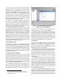
Figure 3 shows the system simulator with a few of its windows open. The top left window shows a simplified view of
the entire system: CPU, instruction and data caches, some
RAM, a console window and some I/O devices. The window
at bottom left shows the register contents of the CPU. The
top right window shows the eight-bit parallel I/O device
which consists of eight LEDs and eight binary switches. Just
as what we have in hardware. The 16-bit parallel I/O-port is
the only one from the hardware that is not implemented in
the simulator. The bottom right window shows the simple
interrupt sources. Two push-buttons and an adjustable pulse
timer.
The main reason for developing this simulator is because
it simplifies for the students to study computer organization
on their own, at home. Most students have access to PCs
with Windows and it is therefore easy for them to download
the simulators and development environment to start work
on their own.
However, as we designed the laboratory exercises, we
found that the simulator could actually be used also in the
class-room. Figure 4 shows the memory view in the simulator. The memory addresses are shown to the left and the contents is shown to the right as hexadecimal numbers and an
interpretation. In the current view the interpretation is the
disassembler view but other possible views are interpretations as unsigned integers, signed integers, single precision
floating point numbers and ASCII characters.
The dot to the left in the memory view shows a break
point and the line, also to the left, signifies that these instructions are currently in the instruction cache. The darker line
shows the current instruction being simulated.
With this view, the simulator became a powerful tool to
study instruction execution and the effect each instruction
had on the registers etc. Since the MIPS architecture does
not have vectored interrupts, it became cumbersome to single-step interrupt routines on the hardware and we therefore
used the simulator to study interrupt routines in this detail.
The students could also experiment with instruction coding,
making hexadecimal instruction codes by hand, entering
them in the memory and immediately see if they had coded
the instruction correctly. Floating point number coding
could be studied in the same way.
4.2 Cache simulator
Even with all the benefits as described above, these were not
the only purposes for developing the simulator. The major
driving force was to introduce animation to aid the students
to really understand the inner workings of cache memories.
We used the figures of a textbook as an inspiration as how to
present the caches graphically [4].
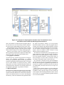
Figure 5 shows the cache view in the simulator. It shows
the current configuration of the data cache. The data and the
instruction caches can be configured independently. It
shows the entire cache contents with both tag and data store.
It also shows how the address presented by the processor is
divided into different fields for indexing, word select and tag