1
2
State Logic Processor Module (SLP)
GFK-0733A
Î
Î
Î
Î
ÎÎ
ÎÎ
ÎÎÎÎÎÎ
a45126
CPU BASEPLATE
C S
P L
U P
PC
DISCRETE/ANALOG/OPTION
Î
Î
Î
Î
Î
Î
ÎÎÎÎÎÎÎÎ
ÎÎ
Î
Î
Î
Î
Î
ÎÎ
ÎÎÎÎÎÎÎÎ
ÎÎÎÎÎÎÎÎ ÎÎ
ÎÎ
ÎÎ
ÎÎÎÎÎÎ
Î
Î
ÎÎ
Î
Î
ÎÎ
ÎÎ
Î
ÎÎÎÎ
EXPANSION BASEPLATE
DISCRETE/ANALOG/OPTION
EXPANSION BASEPLATE
NOTE
TOTAL MAXIMUM
DISTANCE FROM
MAIN BASEPLATE
TO LAST EXPANSION
BASEPLATE IS
50 FEET (15 METERS)
I/O EXPANSION CABLES
IC693CBL300 3 FEET (.9 METERS)
IC693CBL301 6 FEET (I.8 METERS)
IC693CBL302 50 FEET (15 METERS)
DISCRETE/ANALOG/OPTION
EXPANSION BASEPLATE
DISCRETE/ANALOG/OPTION
Î
Î
Î
Î
ÎÎ
Î
ÎÎ
Î
Î
Î
ÎÎÎÎÎ
ÎÎ
ÎÎ
ÎÎ
EXPANSION BASEPLATE
LEGEND:
SLP
STATE LOGIC PROCESSOR
CPU
MODEL 331 OR 341 CENTRAL
PROCESSING UNIT
I/O BUS
TERMINATOR
PLUG
1C693ACC307
DISCRETE/ANALOG/OPTION
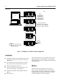
Figure 1. SLP Module in an IC693 PLC System Configuration
Installation
D Installation should not be attempted without referring to the State Logic Processor User’s Guide (see
reference 1).
D The IC693 SLP can only be installed in an IC693
The module should power up and blink the top LED,
indicating that power up diagnostics are in progress.
When the diagnostics have completed successfully the
top LED stays on.
PLC system that uses a model 331 or 341 CPU.
D Make sure baseplate power is off.
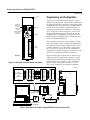
D Connect the battery to either of the battery connectors on the module. (See figure 2)
D Install the SLP Module in the baseplate. (Refer to
figure 1)
D Turn on power.
Memor y
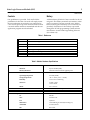
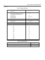
The SLP module has 46 Kbytes of user program
memory space. Additional memory exists for Input,
Output, Register, and other variable data (see table 3).
The battery which supports this memory is located
on the SLP module as shown in figure 2.