1
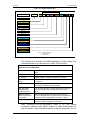
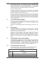
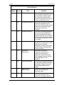
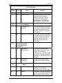
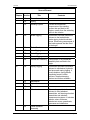
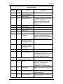
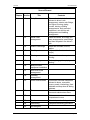
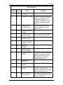
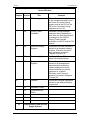
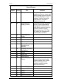
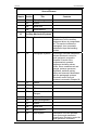
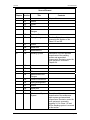
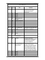
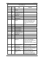
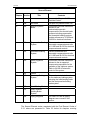
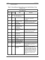
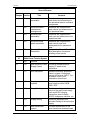
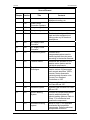
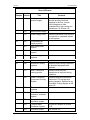
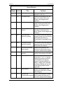
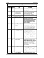
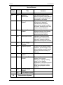
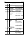
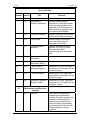
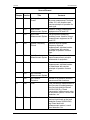
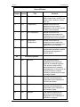
TRANSNET NUMBERING SYSTEM
FOR
INTERACTIVE ELECTRONIC
MANUALS
Document Number: RT/TE/SPC/0269
Document Reference: Transnet Numbering System
Document Date: 30 June 2009
Document Issue: 1
Transnet
Title
Number
Issue
Date
Prepared by
RT/TE/SPC/0269
:
Transnet Numbering System for IEMs
:
RT/TE/SPC/0269
:
1
:
30 June 2009
:
Waymark Infotech (Pty) Limited
Tom Higgins
Waymark
Approved by
Date
:
Date
Transnet
Waymark Infotech (Pty) Limited
P O Box 75434 Lynnwood Ridge 0040
Tel: (012) 369 0000
Fax: (012) 369 0500
Copyright © of this work is reserved under the Copyright Act of the Republic of
South Africa (No 98 of 1978) and the provisions of the Berne Convention. This
work or any part thereof may not be reproduced in any form or by any means
without prior permission in writing of
Transnet Limited unless in pursuance of the recommendations contained herein
30 June 2009
Issue: 1
Page i
Transnet
RT/TE/SPC/0269
TABLE OF CONTENTS
1.
INTRODUCTION
3
2.
PURPOSE
3
2.1
SCOPE
3
3.
REFERENCED DOCUMENTS
4
4.
ABBREVIATIONS AND ACRONYMS
4
5.
SPOORNET NUMBERING STRUCTURE
4
5.1
LOCO CLASS CODE (XXXXXXXXXX)
6
5.2
SERIES (NNNN)
6
5.3
THREE ELEMENT CODE (NN-NNN-XXXXXXXX)
6
5.3.1
First Element (Chapter Number) (NN)
6
5.3.2
Second Element (Section/Sub Section) (NNN)
7
5.3.3
Third Element (Equipment) (XXXXXXXX)
13
5.3.4
Mod Status (XX)
13
5.3.5
Equipment Variant (A)
13
5.3.6
Information Code (NNN)
13
5.3.7
Information Code Variant (A)
13
5.3.8
Item Location (A)
13
5.4
DOCUMENT REVISION RECORDING
13
30 June 2009
Issue: 1
Page ii
Transnet
1.
RT/TE/SPC/0269
INTRODUCTION
The introduction of the updated Class 9E, 11E and 18E locomotives and
the purchase of the new 15E and 19E locomotives introduced equipment,
particularly in the electronic control systems, that had not been used on
SA locomotives before. In addition, Transnet decided to use electronic
viewers in order for engineers and technicians to ‘view’ the technical
support documents for these new and updated locomotives over
Transnet’s Wide Area Network (WAN). This new method of viewing
technical manuals ‘electronically’ required that each ‘bit’ of data be
reduced to a relatively small ‘data module’ and allocated a unique identity.
Technical documents produced as data modules and viewed electronically
over a network are referred to as Interactive Electronic Manuals (IEM).
This series of events caused Transnet to review the numbering system
used for the development of technical documents that has been in use
over many years. The company Waymark Infotech Pty Ltd was selected to
work with Transnet's technical personnel to develop a numbering system
that satisfies the requirements of the new environment. In addition to the
points already listed, the basic requirements for the new numbering
system were:
2.
a.
The numbering system in use throughout various Transnet affiliations
should be retained as far as possible.
b.
The new system should make provision for the technical data sets for
future locomotive purchases.
c.
Uniformity between the different classes of locomotive must be
obtained. For example, the Main Compressor on the Class 18E
should have the same basic identity as the Main Compressor on the
Class 19E, even though they have different specifications and are
manufactured by different suppliers.
d.
Should the need arise, it should be possible to adapt the numbering
system to satisfy the requirements of other types of locomotive such
as diesel electric locomotives.
PURPOSE
This document provides Transnet with a formal numbering system, as well
as the approved data module breakdown, for use in the development of
technical data for all electric locomotives that will use IEMs.
Transnet have selected the aXcess EDMan data module management
software as their software tool for developing IEMs. The business rules
built into the EDMan software will automate a large percentage of the
effort involved in allocating a Data Module Code (DMC).
2.1
SCOPE
This document provides a breakdown of the numbering system to the
detail of a DMC. It also includes a breakdown of the 3-element code that is
used as the ‘heart’ of a DMC and includes the numbers currently used for
the 9E, 18E and 19E equipment.
The nature of changes within locomotives and their equipment will
30 June 2009
Issue: 1
Page 3
Transnet
RT/TE/SPC/0269
undoubtedly result in DMCs being required that are not catered for in this
document. When such a situation arises, the specific documentation
contractor should contact Transnet's Project Manager for advice on how to
number such modules.
3.
REFERENCED DOCUMENTS
The following documents are also applicable to the contents of this
document:
4.
a.
Transnet’s User Guide for Technical Authors, document number
RT/TE/PRO/0217, dated 30 June 2009.
b.
Transnet’s Document Type Definition Manual, document number
RT/TE/PRO/0218, dated 30 June 2009.
c.
Transnet’s aXcess Electronic Documentation Manager (EDMan)
User Manual, document number RT/TE/PRO/0214, dated 30 June
2009.
d.
Specification for Manual and Catalogues for Traction Vehicles,
document number CSS.213/6.05, dated August 1985.
e.
AECMA S1000D, International Specification for Technical
Publications Utilising a Common Source Data Base has been used
as an aid in compiling this document.
ABBREVIATIONS AND ACRONYMS
The following abbreviations and acronyms are used in this document.
Term
5.
Meaning
COE
Centre of Excellence (maintenance facility)
DMC
Data Module Code
IEM
Interactive Electronic Manual
Transnet
All Transnet affiliations involved with IEMs
WAN
Wide Area Network
SPOORNET NUMBERING STRUCTURE
Figure 5.1: shows the numbering structure for a data module to be
developed for a Transnet Electric Locomotive and for viewing as an IEM.
The sub-paragraphs of this paragraph elaborate on the details of the
elements of this numbering structure.
30 June 2009
Issue: 1
Page 4
Transnet
RT/TE/SPC/0269
Figure 5.1: Numbering Structure
Three Element Code
CODE STRUCTURE
XXXXXXXXXX
- NNNN -
NN
-
NN
N
-
XXXXXXXX -
XX
A -
NNN
A
-
A
Loco Class code
Series
Chapter Number
Section
Sub-Section
Equipment
Mod Status
Equipment Variant
Information Code
Information Code Variant
Item Location
Where: X = Alphanumeric character
N = Numeric character
A = Alpha character
The following is an example of a DMC applicable to a data module for a
maintenance task for a component on a Class 18E locomotive.
18E-0000-12-011-01-00A-950A-A
18E - Loco Class Code
Implies the 18E electric locomotive. Refer to paragraph 5.1
below
0000 - Series
Implies the baseline model. Refer to paragraph 5.2 below
12 - Chapter
Implies Chapter 12. Refer to paragraph 5.3.1 below
011 – Section/Subsection
Implies section 01 and sub-section 1. Refer to paragraph
5.3.2 below
01 - Equipment
Implies the first equipment within this sub-section. Please
note that this allocation is project specific.
00A - Mod Status
(Equipment) and
Equipment Variant
The 00 implies that this is original equipment and the A the
first of 26 variants. Refer to paragraphs 5.3.4 and 5.3.5
below.
950A - Information
Code and Information
Code Variant
The 950 implies general maintenance procedures, eg
remove and install, and the A implies that it is the standard
procedure. Refer to paragraphs 5.3.6 and 5.3.7 below.
A - Item location
Implies that the procedure will be performed on the
locomotive. Refer to paragraph 5.3.8 below
DMC 18E-0000-12-011-01-00A-950A-A refers to an 18E Electric
locomotive, baseline model (0000), chapter 12, data module section 01
and sub-section 1 with information relevant to the first component (01) for
30 June 2009
Issue: 1
Page 5
Transnet
RT/TE/SPC/0269
the driver's cab ventilator. The modification status and equipment variant
(00A) indicates that this is still the original component. The information
code and information code variant (950A) indicate it is the standard
maintenance procedure and will be performed on the locomotive.
Notes to the above example:
Only three characters are used for the Loco Class Code in this example
but please note that up to 10 characters can be used in order to allow for
variants to the same basic locomotive class.
Only two characters were used for the Equipment Code in this example,
but please note that up to eight characters can be used. Usually only two
are used in the case of mechanical components but up to eight might be
used in the case of electric components e.g. U1_RY1 will be for Relay No.
1 in Inverter Unit (U1).
5.1
LOCO CLASS CODE (XXXXXXXXXX)
This element identifies the applicable class for the documentation. It refers
to the highest level classification of an asset and will normally be the
complete electric locomotive.
Examples of codes identified for this number element are 18E, 9E, 11E,
etc.
5.2
SERIES (NNNN)
This element identifies the applicability of the data module on possible
locomotive series. This refers to the highest level classification of an asset
variant, such as the electric locomotive.
Examples of codes identified for this number element are 0000 which
implies the locomotive baseline, 0015 implies applicability to series 1
through 4 etc. This is input into the data module as a binary number to
cater for the variety of series’ that might be applicable to a locomotive
class.
5.3
THREE ELEMENT CODE (NN-NNN-XXXXXXXX)
The definitions and allocations for the Three Element Code are defined in
the following paragraphs and, as far as possible, comply with the
numbering system used for older locomotive types that do not have
electronic documentation. The major change to the previous 3-element
number is in the allocation of numbers to electrical chapters 20 to 28.
5.3.1
First Element (Chapter Number) (NN)
Codes identified for this number element are shown in Table 5.1 below.
Table 5.1: First Element (Chapter) Code Definition of Three Element Code
First Element
Chapter
Description
01
Vehicle Complete
02
Extract from Driver’s Manual
30 June 2009
Issue: 1
Page 6
Transnet
RT/TE/SPC/0269
First Element
Chapter
Description
03
General Mechanical Requirements and Procedures
05
Bogie
10
Body and Under-frame
12
Ventilation and Filtration Systems
15
Compressed Air and Vacuum Supply Systems
16
Compressed Air Operated Ancillary Equipment
17
Brake Systems
20
General Electrical Requirements and Procedures
21
Main Power Traction System
22
Auxiliary Systems
23
Driver Ancillary Electrical Systems
24
Locomotive Control
25
Communication Systems
26
Electronic Control Systems
27
Measurement and Detection Systems
28
Indication Systems
5.3.2
Second Element (Section/Sub Section) (NNN)
The Second Element codes, associated with the First Element Codes from
5.3.1 above, are presented in Table 5.2 below for chapters covering
mechanical systems.
Table 5.2: Second Element (Section/Sub-section) Code Definition of Three
Element Code
Second Element
Chapter Section
01
Contents
Vehicle Complete
000
30 June 2009
Title
General
This section provides a basic
introduction to the locomotive and
its functions as a whole with
cross-references where
applicable. It also includes
information for power circuits,
motoring, frame, underframe and
bogies.
Issue: 1
Page 7
Transnet
RT/TE/SPC/0269
Second Element
Chapter Section
30 June 2009
Title
Contents
010
Technical data
This section includes terms and
their meanings as applied to this
documentation. It also includes
the outline and technical data
relevant to the locomotive such as
traction and braking curves
020
Principal Dimensions
This section provides all principal
dimensions applicable to the
locomotive. Should contain a least
a side and end elevation figure
with primary dimensions
indicated.
030
Equipment Layout
This section includes the general
layout of all major equipment in
the vehicle body and the cab(s)
equipment layouts. An end view of
the locomotive showing the piping
and coupling arrangement should
be included.
040
Operating Instructions This section includes the
procedures for starting-up in each
different mode, external
examination, internal examination
and the stabling (shutting down)
of the locomotive.
050
Scheduled
Maintenance
This section includes all
scheduled maintenance by
frequency for all relevant
equipment. These should also
show 'shedding' periods and the
tasks applicable to each
shedding.
060
Lifting And Jacking
This section provides information
for, lifting the complete locomotive
with bogies, lifting the body and
replacing body/bolsters onto
bogies.
070
Mass And Axle Mass Loads
This section includes information
relevant to the mass and
axle/mass loads.
080
Painting
Provides information relevant to
the paint procedures of the
locomotive, including a painting
Issue: 1
Page 8
Transnet
RT/TE/SPC/0269
Second Element
Chapter Section
Title
Contents
diagram and location of logos.
090
02
03
30 June 2009
This section provides information
on safety factors that might
influence personnel. This will
include the fire extinguisher,
warning signs, use of warnings
and cautions in modules, etc.
Driver’s Manual
010
Preparation for
operation
020
Operating Procedures This section provides information
on procedures that are applicable
to technical personnel who are
required to motor (drive and
brake) and/or shut down the
locomotive.
This section provides information
on procedures that are applicable
to technical personnel who are
required to prepare a locomotive
for motoring.
General Mechanical
Requirements and
Procedures
010
Mechanical
Requirements
This section includes general
mechanical requirements such as
torques, lifting of heavy
equipment, etc. It will also contain
any specific Transnet regulations
applicable to mechanical systems
in general.
020
Mechanical
Procedures
This section includes general
procedures for welding, brazing
etc.
05
05
Safety Factors
Bogie
000
General
This section includes an
illustration and functional
description of the complete bogie.
010
Frame
This section includes information
relevant to the frame assemblies,
piping and the sanding system.
Issue: 1
Page 9
Transnet
RT/TE/SPC/0269
Second Element
Chapter Section
05
05
30 June 2009
Title
Contents
011
Frame Assemblies
012
Piping
013
Sanding System
Covers the mechanical
components of the sanding
system that are fitted to the
bogies, usually from the activating
valve to the nozzles.
020
Brake Rigging
This section includes information
relevant to the brake blocks,
brake rigging, brake blocks and
shoes, these being components of
the brake systems that are fitted
to the bogie.
021
Brake Blocks
022
Inner Rigging
023
Outer Rigging
024
Centre Rigging
025
Handbrake Assembly
Components of the handbrake
assembly that are fitted to the
bogie.
030
Spring Rigging
This section provides information
relevant to mechanical, hydraulic
and pneumatic spring rigging. It
covers bolsters, spring planks,
equalizing beams, bolster
anchors, vibration damping
devices and friction snubbers.
031
Mechanical
032
Hydraulic
033
Pneumatic
040
Wheel sets
041
Fixed Wheelset
Assembly
This section provides information
relevant to fixed wheelset
assemblies, self steering wheelset
assemblies and wheelset
measurement systems. It includes
wheels, axles, axleboxes,
attachment covers, gearwheels,
gearcases and odemeters.
Issue: 1
Page 10
Transnet
RT/TE/SPC/0269
Second Element
Chapter Section
05
05
30 June 2009
Contents
042
Self Steering
Wheelset Assembly
043
Measurement
050
Inter-bogie Control
051
Spring Boxes
052
Frame Assemblies
053
Safety Links
054
Safety Clamps
060
Weight Transfer
Equipment
061
Mechanical Weight
Transfer Equipment
Assembly
062
Pneumatic Weight
Transfer Equipment
Assembly
070
Unassigned
080
Motor Suspension
10
10
Title
This section provides information
relevant to spring boxes,
springbox to bogie assemblies,
safety cables and suspension
equipment.
This section includes information
relevant to mechanical weight
transfer equipment and pneumatic
weight transfer equipment.
This section includes all
information relevant to the traction
motor suspension systems and
equipment fitted to the bogie.
Body and Under-frame
000
General
This section includes information
relevant to the body layout,
underframe layout and
procedures for structural repairs.
001
Body Layout
Sides A and B and No 1 and No 2
End
002
Underframe layout
Location of all equipment attached
to the underframe
003
Structure Repair
Specific procedures for repairs to
the loco structure
Issue: 1
Page 11
Transnet
RT/TE/SPC/0269
Second Element
Chapter Section
10
10
30 June 2009
Title
Contents
010
Body Structure
This section includes information
relevant to driver’s cab
arrangement, exterior cab fittings,
roof layout, flooring, piping,
conduit, ducting, cleating
arrangements, body mounted
equipment, non-driver’s cab
arrangement and cladding
arrangement.
011
Driver’s cab
arrangement
Desks and seats, arm rests, sun
visor arrangements, small fittings
and horn lanyards in the driver’s
cab.
012
Exterior cab fittings
Steps and handrails, mirrors,
wipers
013
Roof layout
No 1 end, No 2 end and centre
roof(s)
014
Flooring
Cabs, corridor and compartment
flooring
015
Body ducting
Drains, piping, gutters, piping and
ducting
016
Body mounted
equipment installation
017
Non-driver’s cab
arrangement
018
Cladding
arrangement
020
Doors And Windows
This section includes information
relevant to doors, removable
covers, panels, interlocking, fixed
windows and drop-down & sliding
windows.
021
Doors
Side and end doors, compartment
doors and maintenance doors
022
Covers
Cab’s covers and machine
compartment covers
023
Panels
All control panels with legends
024
Interlocking
Complete interlocking procedure
025
Not assigned
Issue: 1
Page 12
Transnet
RT/TE/SPC/0269
Second Element
Chapter Section
10
10
10
30 June 2009
Title
Contents
026
Not assigned
027
Not assigned
028
Fixed windows
029
Drop down and
sliding windows
030
Under-frame
Structure
030-01
Drag Box
031
Underframe mounted
equipment
031-01
Cow catcher
031-02
Sanding system
031-03
Battery box
arrangement
032
Piping, conduit and
ducting
040
Couplers And Drawgear
This section includes information
relevant to the coupler and
drawgear arrangement and the
coupler release system.
041
Couplers and draw
gear arrangement
At both ends
042
Coupler release
system
050
Equipment Frames
and Equipment
Cubicles
This section includes information
relevant to all equipment frames
and equipment cubicles. Does not
include the electrical equipment
contained inside.
051
Frames
HT, LT and air equipment frames.
Desk frames, aircon mounting
frame, water tank frame and air
duct support frames.
052
Cubicles
The location of all equipment
frames is to be illustrated with
references out to the specific
This section includes information
relevant to the drag box,
underframe mounted equipment
installations and underframe
piping, conduit and ducting.
Issue: 1
Cow catcher, snad box and
battery box arrangement
Page 13
Transnet
RT/TE/SPC/0269
Second Element
Chapter Section
Title
Contents
equipment, examples of cubicles
are HSCB, toilet, and power
conversion equipment cubicles.
10
10
12
060
Insulation, lining and
trimming
061
Insulation
062
Lining and trimming
070
Sanitary System
071
Toilet system
072
Basin system
073
Water supply system
074
Drain system
This section includes information
relevant to the insulation, lining
and trimming used on the
locomotive.
This section includes information
relevant to the sanitary system,
including toilet, water storage,
waste disposal, basin and piping.
Refer out to applicable chapters
for toilet ventilation and lights.
Ventilation and Filtration
Systems
12
000
General
This section provides a
breakdown of different ventilation
systems, cooling systems, heating
and filtration systems provided for
the locomotive. Electronic control
for such systems is covered in
chapters 23 and/or 24.
12
010
Compartment
Ventilation
Provides information relevant to
introducing ambient conditions
into a compartment or cubicle and
includes systems such as
ventilator arrangements, monsoon
arrangements and electronic
cubicle ventilation.
011
Driver’s cab
ventilation
012
Machine
compartment
ventilation
30 June 2009
Issue: 1
Page 14
Transnet
RT/TE/SPC/0269
Second Element
Chapter Section
12
12
12
30 June 2009
Title
Contents
013
Non-driver’s cab
ventilation
020
Equipment Ventilation This section includes information
relevant to ventilation systems
responsible for providing
ventilation to specific equipment
and/or the direct environment
thereof.
021
Traction motor
ventilation system
022
Resistor enclosure
ventilation
023
Driver’s desk
ventilation system
024
Filter Reactor
ventilation system
025
Power Conversion
cubicles ventilation
system
026
Battery box
ventilation
027
Communications
Cubicle ventilation
030
Domestic Cooling
Systems
031
Air-conditioning
System
032
Ancillary Cooling
Systems
Used on Class 9E and 11E.
040
Equipment Cooling
systems
This section provides information
relevant to equipment that
provides cooling for non-domestic
systems and components.
041
Main Transformer
cooling system
This section provides information
on the components used to cool
the main transformer
Issue: 1
On Class 11E and 9E all TM
blower ventilation is covered
under 12-020.
On Class 11E and 9E the Desk
Fan is covered under 12-020-07.
This section includes information
relevant to all domestic cooling
systems. Electronic control for
such systems is covered in
Chapters 23 and/or 24.
Page 15
Transnet
RT/TE/SPC/0269
Second Element
Chapter Section
Title
Contents
042
PCC cooling system
This section provides information
on the components used to cool
the Power Converter Cooling
system such as the PCC on the
19E or the Converter Cooling
equipment on the 11E.
043
Cooling Tower
Ventilation
Describes cooling ventilation
equipment that is applicable to
more than one item of equipment,
for example on the 19E the
Cooling Towers provide
ventilation to the PCC and the TM
blowers.
050
Domestic Heating
Systems
This section includes information
relevant to all domestic heating
systems. Electronic control for
such systems is covered in
Chapters 23 and/or 24.
051
Foot Heating System
On Class 11E and 9E this is
called Cab Heating System.
12
060
Equipment Heating
Systems
This section includes information
relevant to all arrangements
associated with introducing
heated conditions (forced or
natural ventilation) to specific
equipment or systems.
Electronic control for such
systems is covered in Chapters
23 and/or 24.
12
070
Filtration
This section includes information
relevant to the different filtration
components.
071
Ventilation Filters
072
Compressed Air
Filters
073
Vacuum Filters
074
Oil filters
12
15
30 June 2009
Compressed Air and Vacuum
Supply Systems
Issue: 1
Page 16
Transnet
RT/TE/SPC/0269
Second Element
Chapter Section
Title
Contents
15
000
General
This section provides a
breakdown of the air, vacuum and
auxiliary supply systems including
a functional description of such
systems. Electronic control for
such systems is covered in
Chapters 22 and/or 24.
15
010
Compressed Air
Supply Systems
This section includes information
relevant to the compressed air
supply system including valves,
cocks, filters, pressure governors,
regulators, switches, piping,
drains and reservoirs. On Class
11E and 9E the Compressor is
covered under 15-010-01.
011
Compressed Air
Supply
012
Valves
013
Cocks
014
Filters
015
Pressure Governors,
Regulators and
Switches
016
Couplings and Piping
Arrangement
017
Drains
018
Reservoirs
019
Miscellaneous
020
Vacuum Supply
System
021
Vacuum Supply
022
Valves
023
Cocks
024
Filters
025
Vacuum Governors,
15
30 June 2009
This section includes information
relevant to the vacuum supply
system including valves, cocks,
filters, pressure governors,
regulators, switches, piping,
drains and reservoirs.
Issue: 1
Page 17
Transnet
RT/TE/SPC/0269
Second Element
Chapter Section
Title
Contents
Regulators and
Switches
15
15
30 June 2009
026
Piping Arrangement
027
Drains
028
Reservoirs
029
Miscellaneous
030
Aux Compressed Air
Supply Systems
031
Auxiliary Compressed
Air Supply
032
Valves
033
Cocks
034
Filters
035
Pressure Governors,
Regulators and
Switches
036
Piping Arrangement
037
Drains
038
Reservoirs
039
Miscellaneous
040
Reduced Auxiliary
Compressed Air
Supply
041
Valves
042
Cocks
043
Filters
044
Measurement and
Gauges
045
Pressure Governors,
Regulators and
Switches
Issue: 1
This section includes information
relevant to auxiliary compressed
air supply system including minicompressors, valves, cocks,
filters, pressure governors,
regulators, switches, piping,
drains and reservoirs. On Class
11E and 9E the Aux Compressor
is covered under 15-030-01
Page 18
Transnet
RT/TE/SPC/0269
Second Element
Chapter Section
16
16
16
30 June 2009
Title
Contents
046
Piping Arrangement
047
Drains
048
Reservoirs
049
Miscellaneous
Ancillary Mechanical Systems
000
General
This section provides a
breakdown of all the ancillary
equipment driven by compressed
air. This section includes the
pantograph, horn, pneumatic
windscreen wiper and sanding
system.
010
Pantograph Systems
This section includes information
relevant Electronic control for
such systems is covered in
chapters 22 and/or 24.to
compressed air operated
equipment including valves,
cocks, filters, measurement and
gauges, pressure governors,
regulators, switches, piping,
drains and reservoirs associated
with the pantograph systems.
Electronic control for such
systems is covered in Chapter 24.
011
Valves
012
Cocks
013
Filters
014
Measurement and
Gauges
015
Pressure Governors
016
Piping Arrangement
017
Drains
018
Reservoirs
019
Miscellaneous
020
Horn System
Description of the air operated
horn system and associated
components. Electronic control for
such systems is covered in
Issue: 1
Page 19
Transnet
RT/TE/SPC/0269
Second Element
Chapter Section
Title
Contents
Chapter 24.
16
16
30 June 2009
021
Valves
022
Cocks
023
Filters
024
Measurement and
Gauges
025
Pressure Governors
026
Piping Arrangement
027
Drains
028
Reservoirs
029
Miscellaneous
030
Sanding System
031
Valves
032
Cocks
033
Filters
034
Measurement and
Gauges
035
Pressure Governors
036
Piping Arrangement
037
Drains
038
Reservoirs
039
Miscellaneous
040
Windscreen Wiper
System
Issue: 1
The Horn Piping Assembly is
covered in this section on the
Class 11E and 9E.
Description of the air operated
components of the sanding
system and associated
components. Electronic control for
such systems is covered in
Chapter 24.
Description of the air operated
components of the windscreen
wiper system and associated
components. Electronic control for
such systems is covered in
chapters 24. On Class 11E and
9E the Sanding system is covered
in this section.
Page 20
Transnet
RT/TE/SPC/0269
Second Element
Chapter Section
16
16
Title
Contents
050
Sanitary System
051
Valves
052
Cocks
053
Filters
054
Measurement and
Gauges
055
Pressure Governors
056
Piping Arrangement
057
Drains
058
Reservoirs
059
Miscellaneous
060
HT Equipment Air
Supply
Description of the air operated
components of the sanitary
system and associated
components.
Description of the provision of air
to specific HT equipment.
061
062
063
17
17
30 June 2009
Filters
Brake Systems
000
General
This section provides a
breakdown of the braking systems
on the locomotive. Electronic
control for such systems is
covered in Chapter 24.
010
Automatic Train /
Loco Proportional
Brake System
This section includes information
relevant to the functional
operation of the gradual release,
direct release vacuum, electrovacuum and electro-pneumatic
control of the train/loco brakes.
On Class 11E and 9E the CCBII
system is covered in this section.
011
Valves
012
Cocks
013
Filters
Issue: 1
Page 21
Transnet
RT/TE/SPC/0269
Second Element
Chapter Section
014
Title
Contents
Measurement and
Gauges
015
016
Couplings and Piping
Arrangement
017
Reservoirs
018
17
17
30 June 2009
019
Miscellaneous
020
Straight Air Brake
System
021
Valves
022
Cocks
023
Not yet assigned
024
Not yet assigned
025
Not yet assigned
026
Couplings and Piping
Arrangement
027
Reservoirs
028
Not yet assigned
029
Miscellaneous
030
Computer Controlled
Braking II
This section includes information
relevant to the mechanical
components of the CCBII system.
Details of the electronic
equipment are covered in Chapter
26.
031
Electro-Pneumatic
Control Unit
This section includes information
relevant to the EPCU
032
Electronically
Controlled Pneumatic
Brake System
This section includes information
relevant to the equipment used in
the ECP Braking System
033
Wire Distributed
Power
This section includes information
relevant to the mechanical
components of the WDP system.
The electronic components are
Issue: 1
This section includes information
relevant to the operation of the
locomotive independent brake
system and/or train holding
system.
Page 22
Transnet
RT/TE/SPC/0269
Second Element
Chapter Section
Title
Contents
discussed in Chapter 26-070
Trainline Control.
17
040
Not Used
Left open for possible future use.
17
050
Electric Dynamic
Brake
This section includes information
relevant to the
mechanical/pneumatic
components of the electric brake
systems including regenerative
and rheostatic braking systems.
Include references to 21-050 and
24-030 for electrical interfaces.
051
Regenerative Braking
System
Discuss mechanical and
pneumatic components and refer
to 21-050 and 24-030 for electrical
components and controls.
052
Rheostatic Braking
System
Discuss mechanical and
pneumatic components and refer
to 21-050 and 24-030 for electrical
components and controls.
060
Safety Vigilance
System
This section includes information
relevant to the air operated
components responsible for the
operation of the vigilance system.
Refer to 24-060 for electronic
control of the system.
061
Valves
070
Stationary Braking
System
071
Hand/Parking Brake
072
Dual Pressure/
Holding Brake
System
080
Piping Diagrams
17
17
This section includes information
on the stationary braking system
including the hand/parking brake
and the dual pressure/holding
brake system.
On Class 11E and 9E piping
diagrams are covered in this
section.
The Second Element codes, associated with the First Element Codes of
5.3.1 above are presented in Table 5.3 below for chapters covering
30 June 2009
Issue: 1
Page 23
Transnet
RT/TE/SPC/0269
electrical systems.
Table 5.3: Second Element (Section/Sub-section) Code Definition of Three
Element Code
Second Element
Chapter Section
20
20
20
30 June 2009
Title
Contents
General Requirements for All
Electrical Systems
000
General
Electrical standards, HT
requirements, cable and
insulation
001
General electrical
practices
Information relevant to electrical
practices on the locomotive.
002
High voltage
requirements
003
Generic Electrical
Component
Specifications
004
Equipment Earthing
Procedures
010
Electrical wiring
components
011
Cable and insulation
specifications
012
Connection plugs &
sockets
013
Connectors general
014
Not currently used
015
Optical Fibres
General details and specifications
of optical fibres used on the
locomotive.
020
Wiring and assembly
diagrams
Wiring, circuit and electrical
assembly diagrams are normally
viewed via the SPC viewer and
reference should be made to the
applicable collections. On some
classes of locomotive the circuit
diagrams are covered in this
section.
Issue: 1
Information on how individual
electrical cabinets and frames are
earthed to the locomotive
Page 24
Transnet
RT/TE/SPC/0269
Second Element
Chapter Section
21
21
30 June 2009
Title
Contents
021
Electrical frame
assemblies
Describes the components in
each frame and references out
for operational data on individual
components.
022
Electrical cubicle /
compartment
arrangements
Describes the components in
each cubicle and references out
for operational data.
023
Electrical rack
assemblies
Describes the components in
each rack and references out for
operational data.
024
Electrical control
panel assemblies
Describes the components in
each control panel and
references out for operational
data.
025
Electrical Circuit
Description
Only used on Class 11E and 9E.
Brief description of main and
auxiliary power circuits
Main Power Traction System
000
General
010
Main Electrical Power
Supply System
Covers all components that
supply HT power to the
locomotive.
011
Roof equipment
Describe function & purpose of
items in system. Pantograph
control will follow in 24-011. Top
illustration of roof, brief
description of each item
012
Supply protection
systems
Components that protect the
main supply such as HSCB,
CBR, VCB
013
Supply Switchgear
Details on switchgear in the
circuit of the main power supply
such as AC/DC charging
contactors, panto isolators,
AC/DC changeover switches, etc.
014
Supply filtering
Describes equipment that
provides filtering of the main input
supply
015
Main transformer
system
Provides a description of the
main transformer and associated
Issue: 1
Page 25
Transnet
RT/TE/SPC/0269
Second Element
Chapter Section
Title
Contents
equipment with references out to
equipment cooling, etc
016
Power Factor
Correction Systems
017
Not yet assigned
018
Not yet assigned
019
Miscellaneous
21
020
AC Supply Power
Converter
21
030
DC Supply Power
Converter
21
040
Propulsion systems
Includes all HT
components/systems used to
switch/regulate the main power
according to the traction demand.
041
Traction motors
Describes the operation of the
traction motor system and the
individual components.
042
Propulsion
Switchgear
Describes the supply to the
traction motors via components
such as gate amplifiers, IGBTs,
inverter, electro-pneumatic
contactors and converter units.
Covers Four Quadrant
Controllers on 19E.
043
Main resistors
Also covers Armature Converter
on Class 9E and 11E.
044
Weakfield system
Includes Field converter on Class
9E and 11E.
050
Electric Braking
System
Includes all components/systems
used to switch/regulate the
electric braking systems. Refer to
Chap 17 for mechanical and
pneumatic components.
051
Rheostatic braking
system
Refer to Chap 17 for applicable
mechanical and pneumatic
components. Describe electrical
components involved in
21
30 June 2009
Earth return bushgear, AC down
lead and other equipment not
falling under any of the above
descriptions
Issue: 1
Page 26
Transnet
RT/TE/SPC/0269
Second Element
Chapter Section
Title
Contents
rheostatic braking operations with
refs to chap 26 for control
21
21
052
Regenerative braking
system
060
Electrical interlocking
and isolation
061
HT isolating system
062
HT interlocking
system
090
Earthing and Isolating
Equipment
22
30 June 2009
Refer to Chap 17 for applicable
mechanical and pneumatic
components. Describe electrical
components involved in regen
braking operations with refs to
chap 26 for control
Includes systems such as the
Earth Return Brushes, Isolating
Switches, etc.
Secondary/auxiliary electrical
systems/equipment that do not
form part of the
propulsion/braking circuit and
without which the locomotive is
unable to function properly.
Auxiliary Systems
000
General
010
Auxiliary Power
Supply Systems
Systems responsible for the
electrical supply used by the
auxiliary, driver ancillary,
locomotive control, electronic
control power supply and all other
secondary systems. Examples
include Motor Alternator circuit,
Motor Exciter circuit, Static
Inverters, etc.
011
Motor alternator
system
Covers primary aux power
supply system on 9E and 11E.
012
Motor exciter system
Covers battery power and control
system on 9E and 11E.
013
Battery, shore and
emergency supply
Describe each individual subsystem and the respective
components. Include circuit
diagrams to aid in understanding.
Covers 12 and 24V supplies on
9E and 11E.
Issue: 1
Page 27
Transnet
RT/TE/SPC/0269
Second Element
Chapter Section
22
22
22
22
30 June 2009
Title
Contents
014
Auxiliary and control
positive supply
Describe all components that
provide auxiliary electrical
supplies to the loco, include
circuit diagrams to help
understanding. Also covers aux
transformer on 9E and 11E.
015
Steam tender supply
016
Power Supply Units
020
Compressed air
supply systems
021
Main compressor
system
022
Auxiliary compressor
system
030
Vacuum supply
systems
031
Exhauster system
040
Equipment cooling
systems
Describe how cooling is provided
to electrical equipment and
cubicles.
041
Main Transformer
cooling system
Describe how the main
transformer is kept cool during
operation.
042
Power Conversion
Component Cooling
System
Describe how the components
inside the PCC are kept cool
during operation. Referred to as
Converter Cooling System on 9E
and 11E.
050
Forced ventilation
systems
051
Brake Resistor
enclosure ventilation
system
052
Driver’s desk
ventilation system
053
Traction Motor
Ventilation System
Covers Aux blower on 9E and
11E.
054
Converter blower
On 9E and 11E
Describe individual PSUs that are
not specific to a separate system
or sub-system.
.
Issue: 1
Page 28
Transnet
RT/TE/SPC/0269
Second Element
Chapter Section
Title
Contents
055
Brake resistor blower
On 9E and 11E
056
TM blower
On 9E and 11E
057
Radiator (oil cooler)
blower system
On 9E and 11E
22
060
Equipment heating
systems
Description of systems that
provide heating to specific
electronic/electric equipment
22
070
Compartment
pressurization
systems
Methods and associated
equipment for providing
pressurization inside
compartments or cubicles.
23
23
23
23
30 June 2009
Driver Ancillary Electrical
Systems
This section includes the first
level system breakdown
description of all the Driver
Ancillary Electrical Systems,
including a block diagram that
illustrates the interaction of the
various sub-systems with interactive links to their respective
system descriptions.
000
General
010
Domestic cooling
systems
General description, with
references to all domestic cooling
systems on the loco.
011
Air conditioner system
Describe the purpose of the air
conditioner system and of the
items. System circuit diagram.
System interaction at start up.
Ref to frame assembly in Chap
20 and to Chap 12 for
mechanical components.
012
Fridge System
Show location and circuit
description for fridge.
020
Domestic ventilation
systems
General description, with
references to all domestic
ventilation systems on the loco.
021
Toilet ventilation
circuit
Describe the purpose of the toilet
ventilation system and of the
items. System circuit diagram.
030
Domestic heating
General description, with
Issue: 1
Page 29
Transnet
RT/TE/SPC/0269
Second Element
Chapter Section
Title
Contents
systems
references to all domestic heating
systems on the loco.
031
Hot plate circuit
Describe the purpose of the hot
plate circuit and of the items.
System circuit diagram and
locations.
032
Foot heater circuit
Describe the purpose of the foot
heater circuits and of the items.
System circuit diagram and
locations.
033
Warming Drawer
circuit.
Describe the purpose of the
microwave circuit and of the
items. System circuit diagram and
locations.
23
040
Doors ancillary
electrical systems
This section includes all electrical
equipment and the control thereof
associated with doors e.g.
Electronically Controllable Doors,
etc
23
050
Windows ancillary
electrical systems
This section includes all electrical
equipment and the control thereof
associated with windows.
051
Electrical windshield
wiper system
Describe the purpose of the
windscreen wiper system and of
the items. System circuit diagram.
23
060
Domestic electrical
sockets
Describe domestic electrical
sockets, their supply and location.
23
070
Lighting
Purpose of lighting. List subsubsystems -71 to -73. Lighting
supply and protector and timer
circuit diagram How lighting
system in general operates e.g.
delays, voltage limits. Describe
emergency lighting and see-mehome lighting systems where
applicable.
071
Cab Lighting
Describe the purpose of cab
lighting and of the items. System
circuit diagram
072
Corridor and
Compartment Lighting
Describe the purpose of corridor
and compartment lights and of
the items. System circuit diagram.
30 June 2009
Issue: 1
Page 30
Transnet
RT/TE/SPC/0269
Second Element
Chapter Section
30 June 2009
Contents
073
Exterior Lighting
Describe the purpose of exterior
lights and of the items. System
circuit diagram
074
Instrument and
Gauge Lighting
Describe specific additional
lighting that illuminates
instruments and/or gauges.
24
24
Title
Locomotive Control
000
General
This chapter contains all the
electrical control systems,
diagrams and circuits associated
with the main electrical power
system and locomotive motion
control systems
010
Main Electrical Power
Supply Control
System
This section includes information
relevant to the control of the main
electrical power supply. This
section includes the pantograph
control system and the primary
circuit breaker control system.
011
Pantograph Control
Describe the purpose of
pantograph control and of the
items. System circuit diagram.
Mention auxiliary compressor and
main air systems support and
status indication Ref chap 16 &
21 use in conjunction with chap
16 (flow diagram, "fill in" electric
blocks)
012
HSCB control
Describe the purpose of HSCB
control and of the items. Mention
HSCB control instances (e.g. by
Agate) and status indication ref
HSCB itself. Link to chap 21
Normal open & close as well as
trip conditions
013
Emergency System
Describe the purpose of
emergency system and of the
pushbutton. Describe operation
using the circuit diagram. Consist
and alone conditions and
leading/trailing.
014
Current Balance
Describe what happens when
Issue: 1
Page 31
Transnet
RT/TE/SPC/0269
Second Element
Chapter Section
Title
Contents
Protection System
24
30 June 2009
CBR trips. Describe operation
using the circuit diagram
015
PFC Control
016
VCB Control
Describe the operation of the
VCB control circuit using
applicable diagram. Covered
under 24-012 on 9E and 11E.
017
AC/DC Change over
control
Describe the operation of the
AC/DC control circuit using
applicable diagram.
020
Propulsion Control
System
Describe the purpose of the
propulsion control system. State
modes of operation. Methodology
of control. Driver interface
description. Refer to startup
control procedure (chap 1
currently) Referring back to 2140, describe system level
operation. List sub-subsections
021
Stand-Alone, Lead &
Trail Control
Describe the stand-alone, lead &
trail control concept. What
happens on LT circuit, how is
loco configured (contactor wise
for leading or trailing)
022
Forward & Reverse
Control
This section includes all the
control circuits/equipment
responsible for Forward and
Reverse Operation. This General
portion of this section includes
the sequence chart, traction effort
curves and simplified diagrams of
the main power circuit during
Forward and Reverse Operation
023
Series, Parallel and
Transition Control
Describe the way series, parallel
& transition control is achieved
referring to 24-20 and 21-40 and
S59.Describe configurations for
series, parallel & transit. For 18E
use same transition figs as in 6E1
024
Motoring Notching
Control
Describe the way motoring
notching sequencing works
referring to 24-20 and 21-40. Ref
to tractive effort curves in chap 1.
Issue: 1
Page 32
Transnet
RT/TE/SPC/0269
Second Element
Chapter Section
Title
Contents
Referred to as Motor and Braking
Control (Traction Control) on 9E
and 11E.
24
24
30 June 2009
025
Weakfield Control
This section includes all the
control circuits/equipment
responsible for Weakfield
Operation. This General portion
of this section includes the
sequence chart, traction effort
curves and simplified diagrams of
the main power circuit during
Weakfield Operation
026
Manual Cut-out
This section includes all the
control circuits/equipment
responsible for Cut-Out
Operation. The effect of cutting
out equipment must be indicated
as well as the process to do so.
027
Slow speed control
The purpose and method of
selecting slow and/or 2/3 rd
speed must be explained.
Reference must be made to the
tractive effort for each mode.
Covers Bogie/Motor Cut-out on
9E and 11E.
030
Electric Braking
Control
This section includes all the
electrical circuits/equipment
responsible for
rheostatic/electrical braking
operations.
031
Rheostatic Braking
Control
Definition of rheostatic braking
must be supplied as well as effect
of this operation.
032
Regenerative Braking
Control
Definition of regenerative braking
must be supplied as well as effect
of this operation.
040
Pneumatic Braking
Control System
Describe the way pneumatic
braking control is achieved
referring to the system items and
24-40.Ref to braking in chap 17
041
Pneumatic Braking
control
Describe the specific components
involved in this operation.
042
Park brake Control
Describe the specific components
Issue: 1
Page 33
Transnet
RT/TE/SPC/0269
Second Element
Chapter Section
Title
Contents
involved in this operation.
24
25
30 June 2009
050
Adhesion
Optimisation
This section contains all the
electrical systems responsible for
minimising the slipping/sliding of
the wheels on the tracks.
051
Sanding Control
System
Operation of the sanding system
referring to its elements,
indications and the speed
sensor/control system interface.
Automatic & manual mode, refer
buzzer, screen indications.
052
Wheelslip Control
System
Operation of the wheelslip control
system referring to its elements,
indications and the speed
sensor/computer interface.
053
Wheel slide Control
Operation of the wheel slide
control system referring to its
elements, indications and the
speed sensor/computer interface.
054
Electric Weight
Transfer
060
Vigilance System
070
Trainline Control
System
071
Locomotive Trainline
Control
080
External Control
Signals
081
Track Magnet System
Purpose of the vigilance system,
operation, (times, setting up trip,
reset) indications and the control
system interface and listing of
elements.
Purpose of the trainline control
system. Fwd, reverse,
emergency, leading & trailing
using a circuit diagram.
Application of the trainline control
system for locomotive control.
Show wiring diagrams, socket
locations
Communication Systems
Issue: 1
Page 34
Transnet
RT/TE/SPC/0269
Second Element
Chapter Section
Title
Contents
000
General
Purpose of communication
systems & listing of subsystems 10 and -30
010
Driver
Communications
System
Purpose & operation of driver
communication systems, listing
sub-subsystems
011
Communications
Radio System
Operation and system description
of radio communications.
012
Mobile Phone System
Describe mobile phone
installation.
013
Music &
Entertainment
Equipment
Describe music & entertainment
interfaces and components.
014
Train Cab System
Description the operation of TCS
including components, interfaces
and locations.
25
020
Triton System
Provides brief description of
function and equipment of the
Transnet Triton communications
system.
25
030
Tracking & Navigation
Systems
Describe tracking & navigation
systems
031
GPS
Interface of GPS with other
control systems. Describe
equipment, locations, supplies,
etc.
032
Onboard Computer
System
Describes the system and
equipment used to aid the driver
to navigate and track progress.
040
Telemeter Systems
25
25
26
26
30 June 2009
Electronic Control Systems
000
General
This section contains all the pin
definitions, circuits diagrams and
software associated with
Electronic Control
equipment/systems.
010
AGATE System
Description of AGATE system,
listing sub-subsystems -11
through -15. Used for MITRAC
system on 9E and 11E.
Issue: 1
Page 35
Transnet
RT/TE/SPC/0269
Second Element
Chapter Section
Title
Contents
011
Power Supply
Describe system power supplies
012
Controllers &
Interface Definitions
Describe controllers and
connections. Complete interface
(input and output) tables where
applicable. List circuit cards and
their locations in controller units,
for example (MPU/RIOMs)
013
Display & Indication
Describe operation of DDUs and
how to access different screens.
014
Fault Codes
Describe how to access fault
codes and where they are
displayed on the DDUs.
015
Communications
Networks
Describe interfaces. Local FIP
and train FIP, RS 232 & 485,
Data download, DDU
programming, MPU connection
plug
016
Data Loggers & Event
Recorders
017
Programming &
Diagnostic Utilities
26
020
Train Control &
Monitoring System
Description of TCMS, listing subsubsystems -021 through -026 as
for above system.
26
030
Train Cab System
Description of TCS, listing subsubsystems -031 through -036 as
for above system.
26
040
Computer Controlled
Braking (CCBII)
Description of CCBII, listing subsubsystems -041 through -046 as
for above system.
27
Measurement and Detection
Systems
000
30 June 2009
General
This chapter contains all the
measurement and detection
systems. The entire system must
be described from the point of
measurement /detection up to
where the data is electronically
converted and "handed" over for
indication/display or control
purposes
Issue: 1
Page 36
Transnet
RT/TE/SPC/0269
Second Element
Chapter Section
27
Title
Contents
010
Voltage, Current &
Power
General notes on voltage, current
& power measurement, list items
under -011 with locations and
concise principle of operation for
each type
011
Main Power
Measurement System
Used for voltage measurement
equipment on 9E and 11E.
012
Aux Power
Measurement System
List all systems measuring
auxiliary power. Used for current
measurement equipment on 9E
and 11E.
020
Speed, Frequency,
Period
General notes on speed,
frequency & period
measurement, tabulate location
of listed items with concise
principle of operation for each
type
021
Axle Speed
Measurement System
Description of operation of axle
speed measurement principle
and details of equipment.
030
Pressure
General notes on pressure
measurement, tabulate location
of listed items with concise
principle of operation for each
type
031
Air & Vacuum
Measurement System
032
Air Pressure
Detection
Details of air pressure detection
sensors and their locations.
27
040
Flow
This includes the measurement of
the flow rate of liquids/gasses or
the flow limit detection thereof
(HIGH/LOW) E.g. Diesel
consumption measurement using
a flow meter system, Low air flow
detection, etc.
27
050
Liquid Levels
This includes the measurement of
various liquid levels or the level
detection thereof (HIGH/LOW)
eg. Diesel tank level
measurement system, Low oil
level detection, etc.
27
27
30 June 2009
Issue: 1
Page 37
Transnet
RT/TE/SPC/0269
Second Element
Chapter Section
Title
Contents
27
060
Digital Feedback
Digital feedback indicating the
status (open/close, on/off) of any
switch, relay, contactor, control
arm, etc.
27
070
Temperature
Details and functions of
equipments that measure
temperature and provide signals
to their control systems.
071
Air Temperature
Details and functions of
equipments that measure the
temperature of the air in an area
and signal their control systems.
072
Component
Temperature
Details and functions of
equipments that measure the
temperature of components and
signal their control systems.
080
Fire Detection System
Description of the operation of
components that detect possible
fire and provide signals to a
control system.
27
28
Indication Systems
000
General
This section provides a
breakdown of the types and
methods of indication systems.
This section contains all the
electrical/electronic Indication
systems/panels. It also serves as
a quick reference to simple
indication systems that form part
of a larger system.
28
010
Bells & Sirens
This section includes all the
electrical circuits/equipment
responsible for the operation of
the bells and sirens.
28
020
Lights
This section includes all the
electrical circuits/equipment
responsible for the operation of
the indication lights.
28
030
Gauges
This section includes all the
electrical circuits/equipment
responsible for the operation of
indication on gauges.
30 June 2009
Issue: 1
Page 38
Transnet
RT/TE/SPC/0269
Second Element
Chapter Section
Title
28
040
Matrix Panels
28
050
Displays
5.3.3
Contents
This section includes all the
electrical circuits/equipment
responsible for the operation of
indication circuits reflecting on
displays.
Third Element (Equipment) (XXXXXXXX)
The Third Element codes are used for all applicable equipment related to
the Chapter/sub-section. This numbering element is user definable and
starts with 01 for the first component and can go 99 components for a
specific sub-section. For components that have been allocated a
component designator, the third element number will be this designator,
for example -B22 for the Brake Handle and -KREV for the Reverser
Contactor.
When the EDMan software is used, the allocation of data module codes as
per this document can be automated by means of a pick list action and the
rules of allocating the data module codes can be built into the underlying
database. During the use of the above defined numbering system,
deficiencies in the numbering system might be identified. Subsequent
upgrading of the functional definition and application software will be done
in conjunction with the developer and/or other users of the code, following
the approved Configuration Management procedures.
5.3.4
Mod Status (XX)
This element identifies the modification status of the equipment. This will
therefore start at 00 for all components and as a modification is
implemented on a component the element will increase e.g. 00, 01, 02,
0A, 0B etc.
5.3.5
Equipment Variant (A)
Used for alternative equipment differing in design but not enough to
change the subject number of the three-element code equipment. For
example one of two air conditioning units can be installed on the Class
18E but their fit, form and function are identical.
5.3.6
Information Code (NNN)
This element is used to identify the type of information contained in a
specific data module. Examples of Information Codes applicable to electric
locomotives are contained in Table 5.4 below.
Definitions have been compiled using the AECMA Specification S1000,
AE-A-04-03-0000-00A-040A-A, Chapter 4.3, dated 31 May 2004 as a
guideline. Where applicable, categories have been omitted and the
terminology has been changed to be suitable for the Transnet
30 June 2009
Issue: 1
Page 39
Transnet
RT/TE/SPC/0269
environment. It is recommended that the latest issue of this AECMA
Specification be consulted when any definition requires updating or
expansion.
Present documentation available within the Spoornet environment is not
broken down into data modules. This documentation can be numbered by
using the higher levels of the Information Code, for example 280 for
general inspections. As circumstances change and/or documentation is
converted into electronic media, the documentation can be broken down
into data modules and the lower level Information Code allocations can
then be implemented, for example 281 for scheduled inspections and 282
for unscheduled inspections.
Although Information Codes 001 to 009 make provision for front matter
information (pre-amble pages such as title pages, abbreviations, table of
contents, etc.) these codes need not be allocated and pre-amble pages
can be seen as part of the documentation (or data module).
Table 5.4: List of Information Codes
INFOCODE
DESCRIPTION
COMMENTS
000
Description and Operation
General description and theory of
operation of a system, sub-system or
equipment. Details of the structure and
content of 000 data modules for the
different levels are contained in the
Author’s Guide.
005
Abbreviations and Acronyms
Lists of abbreviations and acronyms used
in the IEM. Does not include standard
ISO abbreviations such as AC, DC, etc.
014
Component Lookup Table
Alphanumeric listing of component
designators (items of equipment) with
reference to the chapter and section
where details can be obtained. 014A is
used in chapter 3 for mechanical
components and 014B is used in chapter
20 for electrical components.
017
List of Related Data
References to Transnet specifications
and instructions that are applicable to the
specific locomotive or to all locomotives,
for example Transnet’s High Voltage
Regulations
018
Chapter Contents
Brief description of each system/subsystem, taken from this specification.
There will be a 018 module for each
chapter in the IEM.
021
Reference Module
Used to describe components that are
identical to another component except for
their inputs, outputs and location.
Reference must be made to the Transnet
Author’s Guide for details on the content
and function of reference modules.
110
Controls and Operation
Used to describe the function of controls
and indicators on display screens.
Specific screen content is to be covered
in the applicable description of that
30 June 2009
Issue: 1
Page 40
Transnet
RT/TE/SPC/0269
INFOCODE
DESCRIPTION
COMMENTS
function.
120
Interlock Earth and Unearth
Procedure
Description of the interlock system and
the procedures to earth and unearth the
locomotive.
131
Setting-up Procedure
Set-up a locomotive, system or
equipment for operation.
242
Service
Perform a lubrication service to
equipment.
251
Clean
Specialised cleaning procedures for a
component.
272
Straightening Procedure
280
Inspect
Procedure to confirm a component is
serviceable. Inspections are usually ‘time’
related and details on when specific
inspections should be conducted must
also be included in chapter 01-050.
340
Test
Procedure to perform a test of a system,
sub-system or equipment to confirm it is
operational.
351
Penetrant Inspection
Procedures for inspections that penetrate
into the surface of the component such
as penetrant dye and infra red.
360
Fits and Clearances
Details on fits and clearances for specific
equipment. Details can be included in the
applicable maintenance or overhaul task
if not too lengthy.
450
Test and Fault Finding
At maintenance level.
460
Test and Fault Finding
At overhaul level.
621
Araldite Bonding
Specification
950
Maintenance Procedures
including:
Inspect
Remove
Clean
Repair
Service
Check\Adjust
Fits and Clearances
Install
Test
Provides all procedures applicable to
tasks conducted at maintenance level (on
or adjacent to the locomotive). Where a
specific task is lengthy, a separate
module must be compiled and reference
made to that module from the 950
module. When a specific time or
occurrence related inspection forms part
of a maintenance procedure it should be
addressed in its own
-280 module.
960
Overhaul Procedures
including:
Disassemble
Clean
Inspect
Check/Adjust
Repair
Provides all procedures applicable to
tasks conducted at overhaul level (in a
specialised workshop, depot or COE
installation).
30 June 2009
Issue: 1
Page 41
Transnet
RT/TE/SPC/0269
INFOCODE
DESCRIPTION
COMMENTS
Assemble
Test
5.3.7
Information Code Variant (A)
Used for different data modules applicable to the same subject and type of
information. "A" is always used for the first procedure and "B" for the
second and so on. For example the procedure to fill the Main transformer’s
cooling oil using different containers might be different and would therefore
have an ‘A’ and a ‘B’ module.
5.3.8
Item Location (A)
Used to define the area in which a task will normally be performed, e.g. A
for onboard the locomotive, B for at a workshop and C at a COE.
5.4
DOCUMENT REVISION RECORDING
The revision / version of a document is not seen as part of the document
number, but is an important identifier of the document status and is an
essential part of the configuration management/control process.
In a paper document the revision/version of a document is contained in the
header or footer of each document page as well as on the document title
page. For an electronic document an electronic tag contains the
revision/version control information. The information required for
revision/version control purposes is as follows:
a.
Issue number.
b.
Issue date.
c.
Configuration management responsibility.
d.
Originator.
e.
Applicability.
f.
Quality control status.
The issue number is a direct indicator of the configuration control status of
a document. During the development of a document issue numbers of
000.00, 000.01 to 000.0n are allocated. Once a formal review by Transnet
has approved a document for use, the issue number of the document is
upgraded to 001. From this point onwards this document is under formal
Transnet configuration control. Changes to the document may only be
done after a Change Request has been authorised by the Transnet
configuration control process.
Revisions of the document during the development stage after the Change
Request has been authorised for implementation, are identified by Issue
001.01, Issue 001.02, etc. These issues of the document are however not
for official use within Transnet and are only for use of the project team
implementing the authorised change. After formal review of the updated
document and approval for use within Transnet, the document revision is
30 June 2009
Issue: 1
Page 42
Transnet
RT/TE/SPC/0269
upgraded to Issue 002.00. Issue 002.00 then becomes the only revision of
the document authorised for use within the Transnet environment.
When using Transnet's electronic documentation system (EDMan),
documents of any issue status are under configuration control as per the
inherent functions/features of the software. Documents with an issue
status Issue 00X.01, Issues 00X.02 etc as indicated in this paragraph are
however not formally under configuration control in terms of the official
Transnet configuration management system.
30 June 2009
Issue: 1
Page 43