1
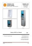
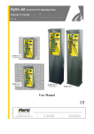
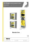
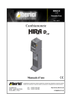
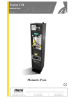
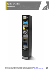
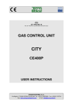
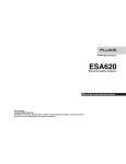
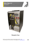
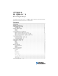
Dry Change Outdoor money changer / token dispenser
Operator’s manual
Rev. 1.02
In-Wall mount
Wall-mount
Free stand
User Manual
DRY CHANGE ALBERICI
Rev. 1.02
Manual
Pagina 1
NOTICE
This manual has been prepared with the utmost care. Nevertheless, it is not
possible to assure at any time the exact correspondence of the descriptiosn to the product features.
Alberici SpA shall not be held liable by the User for any damage, losses, or third party claims
arising from any uses of the manual or of the product .
2
CONTENTS
1.
Package content............................................................................................................................ 5
2.
Product description ...................................................................................................................... 5
3.
Reception and Handling ............................................................................................................... 7
4.
Parts Denomination ...................................................................................................................... 7
5.
Dimensions................................................................................................................................... 8
6.
Installation .................................................................................................................................... 9
7.
Switch-on ................................................................................................................................... 12
8.
Operation .................................................................................................................................... 12
9.
Set up.......................................................................................................................................... 14
10. Messages .................................................................................................................................... 22
11. Maintenance ............................................................................................................................... 24
12. Cleaning of the note recycler ..................................................................................................... 25
13. Disposal of the product .............................................................................................................. 26
14. Terms of Guarantee ................................................................................................................... 26
15. Customer Service ....................................................................................................................... 26
Revisione n°
1.00
1.01
1.02
DRY CHANGE ALBERICI
Rev. 1.02
Data
16.04.12
12.10.12
22.07.15
STORICO REVISIONI
Modifica
Creazione
Hopper S11 invece di HopperOne
Nuovo frontespizio
Note
Manual
Pagina 3
4
Dear Customer,
we would like to thank you and congratulate for your choice. We trust that you will appreciate the
quality and performance of our HYDRO JET control station.
This machine operates by cctalk protocol, the well-established serial communication mode that
provides security and precision.
Please pay careful attention to the information highlighted by the following signs:
IMPORTANT NOTICE REGARDING THE OPERATOR’S SAFETY AND THE PROPER FUNCTIONING
OF THE EQUIPMENT.
IMPORTANT NOTICE REGARDING DANGERS AND RISKS DUE TO ELECTRICITY.
IMPORTANT NOTICE REGARDING DANGERS AND RISKS DUE TO HIGH GEMPERATURES.
GENERAL INFORMATION.
Please read carefully this handbook, to obtain the most from your HYDROJET Station
1.
Package content
The package contains:
1. The Alberici DRY CHANGE unit
2. One pair of security keys
3. User manual (this manual)
4. Options requested, packed separately (i.e. vandal-proof bar, heater kit,
floorstand, in-wall frame, and the like: see page 7)
This product has been packed with the utmost care. If you receive it damaged or incomplete, please
notify immediately your findings to the Carrier, and collect it only under conditional signature.
The packing material, wooden pallets included, must be disposed off according to your Country
laws and regulations. The product itself, once dismissed, must be disposed off according to the
same laws and regulations.
2.
Product description
2.1
Intended use
The DRY CHANGE equipment provides change of notes and coins to coins (one programmable denomination) or to
tokens (one programmable value). It is designed for outdoor installation and functioning, without direct exposure to
weather conditions. It is recommended that it is sheltered from both rain/hail and sun rays.
It is available with floor-stand, for wall-mount, and for in-wall embedding.
This equipment has been certified IP54. However, it is always advisable to install it in a position conveniently
protected against bad weather and strong light.
DRY CHANGE ALBERICI
Rev. 1.02
Manual
Pagina 5
2.2
Available functions
- Change of notes and coins to one denomination coins
- Change of notes and coins to tokens (with or without bonus)
- Programming of coin / token value
- Accounts control on display (only through buttons on the board, or by remote keypad)
- Free custom-configuration (only through buttons on the board, or by remote keypad)
- Interactive User Menu; the User can switch to his preferred language among 5 available
2.3
General Data
Classification:
Protection degree:
Overall dimensions:
Weight (options not considered):
Power supply:
Nominal power:
Peak power:
Operating temperature:
Operating humidity conditions:
Installation:
System components:
Power supply box
Control board
Interface relay board
Display
Banknote reader
Coin Hopper
Coin acceptor
RFID keys cashless reader
Class I equipment ( CEI EN 60335-1), Category IV (CEI EN 55014-2)
IP 54 min. (EN 60529)
400 mm (l) x 698 mm (h - 1698 with floor-stand) x 264 mm (p)
55,50 Kg (wall-mount) - 75,50 Kg (with floor-stand)
24 Vac - 50 Hz
174,80 W (0,76 A)
303,60 W (1,32 A)
0°C ÷ +50°C
40 % ÷ 90% non-condensed
Wall-mount, or embedded into wall (blind niche or open cut-out), or on floorstand.
Power switching 280 W con filtro antidisturbi, e ventilato
Alberici Dry Change CMS ccTalk
Alberici 8PR, each relay 3 A (nominal value)
LCD blue 2 x 16
VEGA ccTalk with stacker (capacity: 300 notes)
HopperOne S11 ccTalk (capacity: 1200 coins/tokens diam. 24mm)
AL66SC wet-proof
Alberici ACS Mifare®
Default currency is the Euro. Please ask in advance for different needs.
2.4
Reference Norms
Development, design and production have been made according to the following EU regulations:
1998/37/CE
On equipments
2004/108/CE (ex 89/336/CEE)
EM compatibility
2006/95/CE (ex 73/23/CEE)
Low voltage equipments
CEI EN 60335
Safety of Electrical equipment
CEI EN 60529
IP Protection
2.5
Warning
- Comply with the instructions in this manual
- Switch power off before any maintenance operation
- Use only within the recommended temperature/humidity range
- Do not expose the machine to direct sun light or to incandescent light (> 3000 Lux)
- Do not use the machine when the ambient temperature and humidity are not within the
recommended Operational range
- When in presence of car exhaust gas or smoke, clean and check the components regularly and frequently.
- Do not favour contact with dusts or chemical moisture or sprays, water or other liquids
- Instal indoor
- Wipe clean by a dry piece of cloth (or slightly wet with alcohol)
- Do not use thinners or organic solvents
- Comply with the instructions given in this manual.
6
3.
Reception and Handling
After testing, the unit and its fittings get carefully packed and separately boxed.
The box(es) get(s) secured to a wooden pallet, so as to reduce to reduce possible damages from
loading/unloading and freight operations.
3.1
Reception
Upon receiving the unit, make use of a forklift truck to move the boxes.
Before signing the reception papers, check the outer state of the boxes. Then open the boxes and
check that the goods have not been damaged during transport. If any damage appears, inform the
forwarder and have your complaint written on the reception papers. Then write “with reserve of
further checking” and sign it. Keep a copy signed by the forwarder.
If the unit(s) must be stored before installing it, keep it inside its box, and store it in a place
protected against deep cold, heat and humidity.
3.2
Opening the box
Cut the tightening belts (take care against possible “whip-lash”. Then remove nylon covers and
protection films.
Take out the fastening staples from the box and open it. Take care not to scratch the unit surfaces
while pulling it out of its box.
Place the unit in upright position.
Please notice: all the packing materials, wooden pallet included, must be recycled or disposed of in
compliance with the existing European, National or local Regulations.
4.
Parts Denomination
OPTIONS
EXTERNAL VIEW
Cashless reader
for RFID keys
Display
AA-0105
Vandal-proof bar Kit
AA-0106
Heater Kit
AA-0116 Printer
Kit
Stop/Language
choice button
Security lock
AA-0901 Protection
shield for coin
acceptor
AA-0117
AA-0119 change
GROUND Footstand
AA-0111
Wall-mount plate
AA-0126 Fastening
plate for GROUND
Footstand
AA-0125
Frame for inwall mount
Coin acceptance
Notes
acceptance
Coins/Token
collection
Protection
screen
(Optional) Printer
DRY CHANGE ALBERICI
Rev. 1.02
AA-0127 Concrete
fitting plate for
GROUND
Footstand
Manual
Pagina 7
POS. COD. ART.
DESCRIZIONE
A
AE-0804
PS Power box
B
SH-1521-1000
ChangeOne
CMS, with display
C
LED-0100
1 x 5-led bar
D
HP-S114
HopperS11 ccTalk STD
E
C-070503-000
Drawer release button
(for Hopper Refilling)
INSIDE VIEW
G
M
I
B
N
D
F
LB-MC0E-0100
Note vaidator VEGA
ccTalk
E
G
C-0701013-000
Security lock
A
H
GE-66SC
Electronic coin acceptor
AL66S ccTalk
O
I
PL-MD0T-000H
Vandal-proof RGB
luminescent pushbutton,
12V
L
AA-0106
Heater Kit optional
M
CH-BC00
ACS ccTalk reader for
RFID keys
N
ADESI-070
Identifying plate
O
AA-0116
Printer kit optional)
5.
H
C
L
F
Dimensions
All measures in mm
900,0
400,0
400,0
8
6.
Installation
6.1
Cautions and dangers when installing
The unit must be installed by qualified technicians, skilled in handling, preparation and mounting,
electric connections, and start-up.
Handle the equipment safely. Make use of safety gloves and shoes. Take care of stability, to
prevent any risk of danger to people.
Even though power supply is 24Vac, keep it disconnected during installation and any further
maintenance or servicing.
Do not modify the circuits in the unit. Any change could impair the correct functioning of the
safety circuits.
The power line must comply with the Norm CEI 64-8/7.
In particolare il conduttore di messa a terra deve essere
inderogabilmente conforme alle prescrizioni, e comunque
avere sezione non inferiore ai limiti stabiliti dalla norma CEI 64-8/4.
Si raccomanda di porre la linea sotto la protezione di un interruttore differenziale da 10A , per
poter agevolmente togliere l’alimentazione caso di operazioni di manutenzione.
6.2
Mounting
The equipment has been certified as IP54 protection degree. However, it is recommended to instal it away from
direct weather agents as rain/hail and sunlight..
6.2.1 Wall-mount :
IT IS ESSENTIAL
THAT THE WALL IS SOLID ENOUGH
TO SUPPORT THE HANGING WEIGHT OF THE UNIT.
40,0
Y
X
X
420,0
X
205,0
See § 6.2.2.1 for electrical connections.
Y
X
720,0
Take the following steps:
1) Fasten the frame to the wall by fischer-bolts,
through the 6 x Φ 10 mm bores (X).
2) Slip the cables through into the unit.
3) Hang the unit onto the four studs (Y), then
tighten the M8 nuts and washers.
95,0
Prepare the wall outlet of the cables corresponding to the
140x80 mm cut-out of the plate.
401,0
160,5
X
X
Y
80,0
The dedicated frame (codice AA-0111) must be used to
fix the Hydro Jet cabinet to the wall.
140,0
140,0
250,0
DRY CHANGE ALBERICI
Rev. 1.02
Manual
Pagina 9
6.2.2 Wall-mount, embedded (blind back):
MAKE SURE
THAT THE WALL IS STRONG ENOUGH TO
SUSTAIN THE WEIGHT OF THE UNIT WITH ITS EMBEDDING
.
Preset the 500x720x210 mm recess for housing the embedding framework (cod. AA-0125): see quotes in the
drawing below.
-
Prepare the 4 holes with anchor plugs for 10mm screws on the back of the recess, corresponding to holes .
pinpointed as ‘X’ in the drawing (vertical inter-axis 420mm, horizontal inter-axis 330mm).
-
Lay the frame in position, and slip the cables through the cut-out “Z”. Fasten the frame to the recess by the
anchor screws.
-
Slip the power cable into the equipment, then fasten the latter onto the 4 holes “Y” (M8 thread).
-
See § 6.2.2.1 for electrical connections.
210
420
180
40
95
500
X
800
720
420
Y
Y
X
205
140
80
Z
45 40
250
40 45
6.2.3 Wall-mount (pass-through embedding):
MAKE SURE THAT THE WALL IS STRONG ENOUGH TO SUSTAIN THE
REAR-WEIGHING BURDEN OF THE UNIT WITH ITS EMBEDDING
Preset the 500x720 mm cut-out for housing the framebox and the unit. See quotes in drawing below.
10
-
Preset 8 holes for Φ10mm screws along the cut-out sides, corresponding to the points “K” in the drawing.
-
Insert in the “K” holes eight M8 threaded bars, long as much as the wall/panel depth plus at least 15 mm.
Set the framebox; fasten the M8 nuts and relevant washers (see figure below).
-
Slip the power cable until inside the equipment, then fasten firmly the equipment itself upon the 4 threaded
holes “Y”.
-
See § 6.2.2.1 for electrical connections.
20
20
WALL or PANNEL
150
K
9
500
Y
150
6
120
260
BOX OUTER FRAME
120
6.2.4 Floorstand mount:
Make sure that the basement is even and strong enough to sustain the weight of the unit with its floorstand.
The pedestal must be secured to the basement by a floor fixing plate (or by the plate for embedding in concrete).
The following operation is better carried out
by 2 persons.
-
Drill 4 holes (Z) on the basement, and fit anchor plugs
in.
Set the plate and fasten it by anchor screws.
Open the floorstand door, fit the floorstand on the plate
according to the latter’s 6 studs.
Take care that the level is horizontal; if necessary, add
spacer washers between the plate and the pedestal base.
Firmly tighten the floorstand by the washers and M8
nuts provided.
Move the power cable up until out of the pedestal. See
§ 6.2.2.1 for electrical connections.
6.2.2.1
175
75
180
z
20
230 120
z z
z
200
230
400
Electrical connections
The power line must be disconected during installation.
Slip the power cable into the equipment by the rear side cut-out. Complete the wires by a 10 Amps 3-pins plug,
and connect it to the machine socket.
If the pedestal includes the “CHANGE” writing, it is possible to make this luminescent: seize the cable from the
equipment power box, slip it through the rear cut-out, then connect it to the cable ready inside the pedestal.
Lock back the pedestal door.
DRY CHANGE ALBERICI
Rev. 1.02
Manual
Pagina 11
7.
Switch-on
Open the equipment door, then release the Hopper drawer by the latch at the right side, and draw the Hopper outwards.
Pour the Tokens or the Coins inside the hopper.
PLEASE TAKE CARE! Refill the Hopper always and only when the machine is off!
Push the hoper back to its operating position. Turn to 1 the switch of the power box, and close the door.
The unit will check the status of the components in the circuit. When the check ends, the display will show the stand-by
message, that can be changed according to the Owner’s wish (see sect. PROMO, in 9.3.9 Menu Functions):
CHANGEONE
Promo
This message appears together with
the following one:
GIVES COINS
or
1,00 €
GIVES TOKENS
0,50 €
The unit is ready for operation.
8.
Operation
Never operate the unit when the door is open!!!
When introducing a banknote or a coin, the display will show the amount, and the unit will automatically pay out the
equivalent value in tokens or coins.
In case the inserted amount is higher than the exact multiple of theavailable token/coin value, the display will show the
remaining credit. Top up the missing amount to obtain an additional change in token(s)/coin(s).
WARNING: if there are no more tokens/coins in the hopper, the unit will not be able to change the whole inserted
amount. The display will show the remaining credit. Switch the unit off, refill the hopper, and turn power on again: the
remaining credit shall be paid and cancelled.
8.1
RFID keys reader
8.1.1 Operation with User Key
When inserting a compatible RFID key (same password of the reader), the available credit gets shown:
If credit is not enough:
If credit is sufficient:
Insert money
Press green button
to load credit
Insert coins and/or notes until the desired value is
The “CHANGE” button will lit steady green. Press it to
attained, and press the green flashing button.
get the change.
Wait until the following message disappears:
To load more credits, insert as many notes and/or coins as
you want to add up. Then, insert the key. The display will
Data are being stored
…….
prompt you to:
Press
CHANGE
The “CHANGE” button will lit steady green. The key
contains credit now. Therefore it can be removed, or
Press the “CHANGE” button to transfer the inserted
the green button can be pressed to get the change.
credit onto the key. Then remove the key.
12
8.1.2 Operation with Service or Master Key
Insert the Service Key (white) or the Master Key (black) to get access to the Service Menu (no need to open the
machine). Otherwise it is necessary to open the machine and act on the menu buttons behind the display.
The Service menu allows to: 1) initialize the User Keys, as well as 2) check the Accounts Data.
The Service Key is allowed to reset the Partial Accounts data, while the Master Key can reset all Accounts and - if
the printer is installed - also print Account records (see procedure at page 17).
Insert
Service or
Master Key
Press
green button
INITIALIZE
KEYS
ACCOUNTS
4 seconds
4 seconds
Notes IN
0,00 €
Insert key
to initialize
Insert
User Key
Coins IN
0,00 €
DO NOT REMOVE
THE KEY…..
Wait ……
(*)
Coins OUT
0,00 €
KEY
INITIALIZED!
Remove the
initialized key
Cashless IN
0,00 €
(*) If the key is
not compatible,
the message:
“KEY NOT
ENABLED” is
displayed
Insert key
to initialize
Insert another
User Key, or
after 10 seconds:
Cashless OUT
0,00 €
Automatic
exit
Tot. Left Credit
Paid:
0,00 €
Reset
Partial data
Confirm Reset?
4 seconds
Remove Service Key
All partial reset
Automatic
exit
Automatic
exit
DRY CHANGE ALBERICI
Rev. 1.02
Manual
Pagina 13
9.
Set up
9.1 Default configuration
Default presettings are as follows:
PCBoard Parameters
Type of distribution
Bonus
Level Sensors
= AUTOMATIC
= DISABLED
= DISABLED
Hopper HopperOne [ccTalk]
Coin/Token value
= € 0.50
AL66S [ccTalk] coin acceptor
€ 0.50 - …. - € 2.00
= ENABLED
VEGA Note reader [ccTalk]
€ 5.00 - …. - € 100.00
= ENABLED
If unwanted modification are made, the default configuration can be restored from the control board buttons (on the
board housing, behind the display) as follows:
- press OK (cfr. 7.3.1 SCROLL MENU), then:
- by UP or DOWN find RESTORE DEFAULT CONFIGURATION , then
- press again OK; the message ” Default Configuration restored” will be displayed.
PLEASE NOTE: the command RESTORE DEFAULT CONFIGURATION will reset also the default PIN code ( 0000 ).
9.2 ACS Reader for RFID Keys
If the unit is equipped with the ACS reader, it is possible to get access to useful functions,
depending on the key used:
OPERATION
1. Inizialize Service and User keys
2. Load Credit on keys
3. Check Accounts (totals and partials)
4.
5.
6.
7.
8.
9.
Check Accounts (partials only)
Print Accounts
Reset Accounts Data (all)
Reset Accounts Data (partials only)
Reset of paid residual credit
Access to (optional) Refill
MASTER KEY
(BLACK) FOR THE
SERVICE KEY
(WHITE) FOR THE
OWNER
MANAGER
YES
YES
(from Menu)
YES (depending
on board version)
YES
YES
YES
YES
YES
YES
NO
NO
USER KEYS
(COLOURED)
NO
YES
(from reader)
NO
NO
YES
NO
NO
YES
YES
YES
NO
NO
NO
NO
NO
NO
The Master key allows to initialize and identify the Service Key(s). Access to this sensible
function is allowed only by entering the PIN code.
Whenever the Master Key or the Service Key gets access to the Accounts menu, the shown data are
automatically downloaded in the key. Each key can contain up to 10 downloaded sets, from the
same unit or from different units.
14
9.3 Menu Functions
9.3.1
SCROLL THE MENU
To enter the menu and navigate it, make use of the 3 keys located behind the board display side.
CMS board for DRY
CHANGE
+
+
P
P
R
O
G
PR
RO
OG
G
--
O
O
K
OK
K
(when Printer is included,
CCS board with CMS
software must be used)
S
S
T
P
ST
TP
P
Rear View
P
P
T
PT
T
T
T
S
T
TS
ST
T
P
P
4
/
7
R
G
B
3
R
G
B
2
R
G
B
1
P4
4/
/7
7R
RG
GB
B3
3R
RG
GB
B2
2R
RG
GB
B1
1 S
S
P
1
SP
P1
1
PWR IN
C
C
C
1
2
CC
C1
12
2
C
C
C
T
CC
CT
T
2
2
4
24
4
R
R
E
G
RE
EG
G
P
P
W
R
PW
WR
R
O
O
U
T
OU
UT
T
P
P
W
R
PW
WR
R
IIIN
N
N
2
2
4
1
2
G
N
D
24
41
12
2G
GN
ND
D
POWER IN
24 12 GND
CC12
COIN ACCEPTOR & RFID KEY READER
CCT 24
HOPPERONE S11
PWR OUT
Pin 1. CCT
Pin 2. GND
Pin 3. +12V
Pin 4. +24 V
RGB 1,3
Pin 1. MICRO N.O.
Pin 2. LED R (rosso)
Pin 3. +12V
Pin 4. LED B (blu)
Pin 5. GND
Pin 6. LED G (verde)
[ NOTE VALIDATOR or
ACS READER for RFID KEYS (12V) ]
[PUSHBUTTONS RGB: RGB1 = Printer; RGB3 = Select/Language]
OK button
enter the set-up menu or chosen menu; confirm chosen data
+ / – buttons
surf the menu; modify figures or characters
To exit the menu, click + (UP) or – (DOWN) until EXIT voice shows,
then confirm Exit by the OK key.
9.3.1.1
RESET OF RESIDUAL CREDIT:
If there are not enough coins in the hopper to fulfil the whole exchange request, the remaining
credit shall be displayed and retained in memory. Switch off the machine, fill the hoppers, and
switch on again: the remaining credit shall be paid out.
As an alternative, it is possible to cancel the message of remaining credit by an additional pushbutton or switch keylock (not provided), and pay manually the credit left. Just connect the pushbutton or switch key-lock between pins 1
and 5 (common GND) of socket p4/7.
The cancelled remaining credit will be recorded in the Show Accounts menu (see section 9.3.4).
Notice: access to some sub-menus is protected by the PIN.
DRY CHANGE ALBERICI
Rev. 1.02
Manual
Pagina 15
9.3.2
MENU STRUCTURE
CHANGEONE
Promo
SHOW
PERIFERAL UNITS
EXIT
MENU
SHOW
ACCOUNT RECORDS
RESET
ACCOUNT RECORDS
SET UP
PERIFERAL UNITS
EMPTY THE
DISPENSER
RESTORE
DEFAULT CONFIG.
PROMO
BONUS
SET UP
LANGUAGE
EXIT
MENU
16
CHANGE PIN
(appears only if equipment is preset for
dispensing TOKENS)
9.3.3
SHOW PERIPHERAL UNITS
This function shows the state of the input and output devices, for instance:
NOTE VALIDATOR
CONNECTED
9.3.4
COIN COUNTER
CONNECTED
NOTE DISPENSER
EMPTY
COIN ACCEPTOR
DISCONNECTED
a.s.o.
CHECK ACCOUNT RECORDS
SHOW
ACCOUNTS
RESET
ACCOUNTS
Exit
Total in
00,00 €
IN:
OUT:
00,00 €
00,00 €
Total out
00,00 €
Remained Credit
Paid
00,00 €
Last partials
cancelled
(*)
Banknotes in
00,00 €
Banknotes out
00,00 €
Coins out
00,00 €
Coins in
00,00 €
(*) Reset of the remaining credit: if and when the relevant contact circuit has been preset (see section 9.3.1.1), it is possible to switch the
reset button or key to cancel the unpaid amount. The Operator will then manually pay the credit left to the Customer, while the cancelled
amount will be recorded in the Accounts section (see 9.3.5 RESET ACCOUNTS).
-
Press OK: the display will show the total amounts introduced (TOTAL IN). Press UP, and OK if
you want to exit the ACCOUNTS menu.
Or else, press DOWN to check the total amounts dispensed (TOTAL OUT).
Press DOWN to go on browsing the submenu.
Notice: whenever the Partial Amounts record get cancelled (see section 9.2.3 RESET ACCOUNTS), the previous value
recorded in “Last Partials cancelled” gets replaced by the amount that has just been reset.
PRINT ACCOUNTS: when the machine includes the printer and the RFID Keys Reader, it is possible to get a strip reporting
the sate of the accounts. Proceed as follows:
1. Insert Master (Black) key.
2. Display shows “Account Records”: hold the greenlit (Lang.) pushbutton pressed until display shows “Partials in”
(depending on board version, it can show other descriptions).
3. Navigate the Accounts menu until finding “Print Accounts” (depending on board version), or else go straight to 4.
4. Press Printer Pushbutton (“STAMPA RICEVUTA”): its light will flash yellow as long as the printing goes on.
9.3.5
RESET OF ACCOUNTS
To use this sub-menu it is necessary to digit the PIN code. This function allows to cancel the account records (both paid
out and cashed in) of the machine.
RESET
ACCOUNTS
(*)
Exit
For each of the 4 digits of
thePIN, use UP and DOWN to
highlight the figure wanted, then
confirm by OK. At the end, the
display will show:
Once entered the PIN,
the display will show:
DRY CHANGE ALBERICI
Rev. 1.02
Reset
Total Amounts
Reset
Partial Amounts
Enter PIN
All Partials
cancelled
0
All Totals
cancelled
Exit
PLEASE NOTE: when re-configuring the unit from token
dispenser to coins dispenser, always activate RESTORE DEFAULT
CONFIGURATION and then RESET ACCOUNT RECORDS.
If not done, memory of the bonus given would fauls the audit.
Manual
Pagina 17
9.3.6
PERIPHERAL UNITS SET UP
It is possible to configurate by this menu the cctalk coin acceptor, the ccTalk note validator, the ccTalk hoppers, the
pay-out mode and the keys mode.
PERIPHERAL UNITS
EMPTY OUT
HOPPERS
SETUP
Set up
Note validator
Exit
5 < 10 > 20 50 100
OK OK OK OK OK
5 10 < 20 > 50 100
OK OK OK OK OK
< 5 > 10 20 50 100
NO OK OK OK OK
5 < 10 > 20 50 100
NO OK OK OK OK
2,00
OK
< 5 > 10 20 50 100
OK OK OK OK OK
Set up
Coin acceptor
< 2,00 >
OK
1,00
OK
< 1,00 >
OK
0,50
OK
2,00
OK
1,00
NO
1,00
OK
0,50
OK
2,00
NO
< 1,00 >
OK
< 0,50 >
OK
0,50
OK
< 2,00 >
NO
0,50
OK
(**) DO NOT USE TOKENS in HopperCD!
Set up
Cashless
Set up
COINS
Set up
Dispense mode
(**)
Set up
TOKEN
(**)
Set up
TOKEN + CHANGE
(*)
Set up Hopper 1 :
1,00 €
Level sensors
enabled
(***)
(***)
Dispensing mode
MANUAL
Dispensing mode
AUTOMATIC
(*)
Set up Hopper 2 :
0,50 €
(*) Press Down or Up
to modify amounts in
discreet steps of 0,05
€ each
(***) available only in
HAMMER1 CD+CD
Level sensors
disabled
- Note Validator setup
All the programmed note values (5-to-100 GBP) get automatically enabled. To modify this default condition, press OK
to get to the first option (ex. 5 €) and highlight it, then press UP or DOWN to reverse its state. Press OK to shift to the
next option (ex. 10 €).
Set up
Note validator
< 5 > 10 20 50 100
OK OK OK OK OK
< 5 > 10 20 50 100
NO OK OK OK OK
5 < 10 > 20 50 100
OK OK OK OK OK
5 10 < 20 > 50 100
OK OK OK OK OK
- Coin selector setup
Among the accepted coins (0.05-to-2 €), the following ones get enabled by default: 0.50 € - 1.00 € - 2.00 €. To modify
this condition, press OK to get to the first option (ex. 2 €) and highlight it, then press UP or DOWN to reverse its state.
Press OK to shift to the next option (ex. 1 €).
18
Set up
Coin acceptor
< 2,00 > 1,00
OK
OK
0,50
OK
< 2,00 > 1,00
NO
OK
2,00
OK
0,50
OK
2,00
OK
< 1,00 >
OK
1,00
NO
0,50
OK
< 0,50 >
OK
- Dispensing Mode setup
Allows to choose whether to dispense COINS or TOKENS or TOKENS+CHANGE, and whether the DISPENSING MODE will
be AUTOMATIC or MANUAL.
It also permits to monitor the level of the coins in the hopper(s) by the electronic sensors.
SET UP
DISPENSING MODE
Set up
TOKENS
(**) NOTICE:
option TOKEN+CHANGE
available only in BIG CHANGE,
not available in DRY CHANGE
(*) Use keys Down and Up to modify values
Hopper 2 does not show in DRY CHANGE
Set up
COINS
(*)
(*)
Set up Hopper 1:
1,00 €
Set up Hopper 2:
0,50 €
(**)
Dispense mode
AUTOMATIC
(**)
Set up
TOKENS+CHANGE
Dispense mode
MANUAL
Level sensors
enabled
Level sensors
disabled
NOTA: monitoring of level sensors is disabled by default. This means that the board does not know when the hopper is
empty, so it will send the pay-out command even if there are no coins available.
If instead the monitoring has been enabled, and there are not enough coins in the hopper, the display will warn that the
hopper is empty. There are yet contained 20 coins approximately, to be able to complete the change payout.
PLEASE NOTE: IF AND when re-configuring the unit from token dispenser to coins dispenser, always activate
RESTORE DEFAULT CONFIGURATION and then RESET ACCOUNT RECORDS. If not done, the memory of
the bonus given would make the accounting false.
- Cashless Set up (only if the ACS reader is built-in)
At first pressing OK to enter this menu, the display will request to initialize the key reader. Do as follows.
Insert the Master Key (black). Work out one 6 digits PIN code, write it down and keep it in a safe place.
Press the OK button: you will be prompted for entering the PIN code.
Enter PIN
Insert the 6 digits PIN. To enter each of the 6 digits, make use of the
0
UP and DOWN buttons. When the desired character is displayed,
confirm it by the OK button.
After entering the 6th character, the display will prompt for confirming the PIN code. Enter it again: initialization of the
key reader will start. The Master Key gets initialized as well.
Antenna
Once the process is complete, the confirmation message appears:
initialized!
The display will return to “Peripheral Units Setup”.
DRY CHANGE ALBERICI
Rev. 1.02
Manual
Pagina 19
Go again to “Cashless Set up”, and press OK button to initialize the Service key(s) and/or the User Keys. This time the
4 digits PIN of the unit will be requested (see section 9.3.13 Change PIN).
To create another Master Key, it will be necessary to use again the 6 digit PIN.
Let us now initialize the Service key - insert it:
Init. Service
Key
Insert Service Key
(white)
Let us now initialize the User key
Init. User
Key
Do not remove the
key
Wait……
Key
initialized!
Remove the
initialized key
Wait……
Key
initialized!
Remove the
initialized key
- insert it:
Insert User Key
(coloured)
Do not remove the
key
NOTICE:
it is possible to load the User Keys either by the
same key reader in the unit (see section 8.1.1), or
by the ACR programming station (K-P4N-000007).
9.3.7
ACR programming station
for RFID keys (K-P4N-000007)
EMPTY OUT THE HOPPER
Use this function to make the selected hopper pay out all the contained coins / tokens.
EMPTY OUT
HOPPER
EMPTY OUT
HOPPER 1
Exit
total
nnn,nn €
When depletion has been completed, the paid out value will be displayed.
9.3.8
RESTORE DEFAULT CONFIGURATION
To use this sub-menu it is necessary to digit the PIN code.
The following message will briefly appear
RESTORE DEFAULT
EnterPIN
after the PIN has been entered, then the
CONFIGURATION
0…
message DEFAULT CONFIGURATION
RESTORED will be shown again.
If a wrong number is inserted, the following message will appear:
DEFAULT CONFIG.
RESTORED
PIN error
WARNING: in case of reset, the system sets back to default configuration. The PIN code will be reset to the default
0000 setting. Account records shall not be cancelled.
9.3.9
PROMO
It is possible to preset an advertisment on the display. Press OK:
Digit text
------------------------
Press again OK, the pointer will highlight the first digit: by UP or DOWN, choose the character that you want to insert,
then confirm by OK. The pointer will highlight the following digit.
Once digit nr. 16 has been confirmed, the message gets stored.
20
9.3.10
BONUS SET UP
This function will operate only if at least the hopper nr. 1 is preset for paying tokens. Take care to set up all hoppers
parameters. Bonus function is disabled by default.
BONUS
Bonus
ENABLE?
Bonus settings
stored
Bonus
DISABLE?
LEV
0
EURO
1€
PCS
1
LEV
1
9.3.11
PCS
1
(*)Use Up key to modify
values
(*)
(*)
NOTICE: in case of mistakes
made, do confirm the wrong
programmed data, then reprogram correctly.
EURO
1€
LEV EURO
1
10€
PCS
11
LEV EURO
1
10€
LEV EURO
2
10€
PCS
11
LEV EURO
2
10€
PCS
1
PCS
11
LEV EURO PCS
1 2..3..10 €
1
LEV EURO PCS
1
11..12.. €
1
SET UP LANGUAGE
LANGUAGE
SETUP
Seleziona lingua
ITALIANO
Choose your language
ENGLISH
Waehlen Ihre Sprache
DEUTSCH
9.3.12
CHANGE PIN
The PIN code allows to get access to the discretional menus of the system.
The PIN code is made up by 4 figures (each of them from 0 to 9), so that there are 10,000 combinations available.
If the PIN code is not correct, the User is given another 4 tries before the board gets blocked-up by its security interlock.
The system can be started again by switching it off and on again.
ATTENTION: the default PIN code is 0000
The settings in the following menus can be modified by using the PIN code:
MODIFY PIN - RESET ACCOUNTS - RESTORE DEFAULT CONFIGURATION
DRY CHANGE ALBERICI
Rev. 1.02
Manual
Pagina 21
To modify the existing PIN, press OK, and digit the old PIN code: to digit each code figure, use keys UP and DOWN to
set each character, then confirm it by OK. Once the 4th character has been confirmed, confirm by OK the old PIN:
Enter PIN
0
MODIFY PIN
New PIN
0
To digit the new PIN code, use first the UP and DOWN keys to set each figure, then confirm it by OK. Once the 4th
figure has been confirmed, confirm by OK the whole new PIN.
As every single figure gets confirmed, an asterisk takes its place, so preserving secrecy.
NOTICE: when DEFAULT CONFIGURATION is restored, the PIN code gets reset to 0000.
7.3.13
EXIT MENU
Press OK to go back to stand-by condition:
Exit Menu
in progress…
EXIT MENU
10.
Messages
10.1
Messages of faulty operation
When this warning appears:
CHANGEONE
Promo
DRY CHANGE
OUT OF SERVICE
please check the state of the Peripheral Units:
COIN ACCEPTOR
CONNECTED
NOTE VALIDATOR
IN ERROR
HOPPER N. 1
DISCONNECTED
The above messages mean that:
the coin acceptor is connected and functioning
there has been a problem with the note reader
hopper n. 1 is disconnected.
The following information can appear:
(PERIPHERAL UNIT)
CONNECTED
(PERIPHERAL UNIT)
the named peripheral unit (coin acceptor, or cashless reader, or 8PR relay board,
a.s.o.) is correctly operating
the named peripheral unit has not been detected
DISCONNECTED
(PERIPHERAL UNIT)
ERROR
(PERIPHERAL UNIT)
NOT SUPPORTED
BANKNOTE
NOT ENABLED
22
the named peripheral unit has been detected but
there has been a malfunction
the named peripheral unit has been detected but
it is not supported by the control board
A disabled note denomination has been introduced, and rejected
10.2
Code RI (Control Board blocked)
The ‘Code RI’ message means that there has been an event that makes it wise to hold the EPROM from operating.
If and when it pops up, hold down the 3 OK, UP e DOWN keys at the same time for 5 seconds.
Such operation will reset the machine to its default configuration. It will then be necessary to re-program the setup
according to the needs.
In case that the ‘Code RI’ message pops up again after releasing the 3 keys, it means that the EPROM has been
damaged: it will be necessary to replace the board.
10.3
Messages from the note reader
The Leds in the front entry of the validators inform about malfunctions. The following chart shows the possible cases:
State of the
unit
Colour
Nr. of
flashes
Error description
Suggested solution
The machine display will also report an error
none
Power off
none
Communication with
control board interrupted
Out of service
none
Out of service
yellow
none
variable
Jammed notes
red
variable
Rejected notes
yellow
variable
Diminished
acceptance
rate
yellow
variable
DRY CHANGE ALBERICI
Rev. 1.02
CPU out of service
ROM or RAM out of
service
notes or parts clogging the
reading path
Configuration
malfunctioning
DIP switches have been
wrongly set
Sensors are dirty
Sensors malfunction
The machine display will also report an
error. Check that the dip-switches are
correctly set
The machine display will also report an
error. Check connections and cables inside
the validator
See Vega manual, chart 13, according to the
number of flashes
Check the reading path
See Vega manual, chart 13, according to the
number of flashes
See Vega manual
Clean the sensors in the reading path
See Vega manual, chart 14, according to the
number of flashes
Software not updated to
Check that the note and its minting year are
recently minted notes
consistent with the software update version
Sensors are dirty
Clean the sensors in the reading path
Check the flashing pattern, then See Vega
Sensors calibration required manual, chart 14, according to the number of
flashes Carry out the calibration test.
Manual
Pagina 23
11. Maintenance
!
PLEASE PAY ATTENTION! Switch power off before opening the validator.
- Retrieving Banknotes
1. Pull the Release Handle to free the Cash Box
from the Frame and pull the Cash Box forward.
2. Rotate the Thumb Lock Knob counterclockwise
and drag down the Cash Box Door
3. With the Cash Box Door open, retrieve the Banknotes
3
1
2
- Clearing a Banknote Jam
A
1. Do not power up the validator during this operation.
2. Press buttons A and lift the Upper Validation
Section open.
3. Remove the Course Reversing Guide Cover by
pressing in on the two buttons B.
4. Turn the Thumb Lock Knob C to gain access to the
jammed Banknote
5. Remove the jammed Banknote or any foreign object
jamming the transport path.
B
C
- Clearing a Banknote jammed in the stacker
1. Do not power up the validator during this operation.
2. Remove the cash box.
3. Rotate the Cash Box Banknote Transportation
Gear in the necessary direction to remove the
jammed Banknote.
Transportation Gear
24
12.
Cleaning of the note recycler (only for BIG CHANGE UNIT)
CAUTION:
Do not use alcohol, thinner or citrus based products for cleaning any inner or outer surfaces.
Cleaning the Banknote Recycler’s Transport path is very important. Adhering Iron powder or dirt on the Recycler’s
Sensors may cause poor performance or errors. Perform a scheduled clean-ing at least once a month to keep the
Recycler Transport path clean. Use a dry, soft, lint-free cloth or a Cotton swab to wipe dirt and stains from the Magnetic
and Optical Sensors, Rollers and Belts. If necessary, blow the inside of the Unit clean with a compressed air jet to
remove clinging foreign objects. Pay attention not to scratch the sensors lenses.
How to clean the sensors:
1. Make sure that power is off.
2. Open the upper cover flap.
3. Clean each sensor and its path.
a
Wipe clean by a lint-free piece of cloth:
a – Input Sensor
b – Validation Sensor
c – Side Sensor
d – Escrow Sensor
b
d
c
f
e
g
b
h
Clean by pressurized air:
e – Recycler flap Sensor
f – Stacker door flap Sensor
h – Cash box present Sensor
i - Pusher mechanism home position Sensors
a
Clean by cotton swab:
g – Stacker input Sensor
i
DRY CHANGE ALBERICI
Rev. 1.02
Manual
Pagina 25
13.
Disposal of the product
WARNING! DISPOSE OF ACCORDING TO THE GOVERNING LAW
IN YOUR COUNTRY!
This equipment may not be treated as household waste. Instead, it must be
handed over to the applicable collection point for the recycling of electric and
electronic equipment.
By ensuring that this product is dised of correctly, you will help to prevent
potential negative consequences for the environment and human health, which
could otherwise be caused by inappropriate waste handling of this product.
For more detailed information about recycling of this product, please contact the
Dealer where you purchased this product.
14.
Terms of Guarantee
The manufacturer will fix malfunctions arising from production faults in this machine or parts of it within 12 months
from the date of sale.
All communications referring to guarantee repairs or replacements must be accompanied by the product serial number
and the copy of the sale invoice.
To obtain your guarantee repair, please send the part to the Dealer where you purchased the machine, together with the
following documents:
- copy of the sale invoice
- delivery note stating “returned for guarantee repair”
- detailed report of the problem found and the circumstances in which it occurs.
Before sending the product, please get in touch with your Dealer or with Alberici S.p.a. (+39 051 944300); very
malfunctions can be fixed via a simple phone call, saving you costs and time.
Alberici S.p.a. will verify that warranty is applicable, i.e. that problem is not caused by:
- transport damages
- damages from incorrect installation or wrong configuration
- installation in premises or areas not complying with the prescribed safety requirements
- intentional or unwilled tampering
- wrong or careless use or maintenance
- non-compliance with precautions prescribed (see Chapter 4. Caution)
- natural disasters, vandalisms, intentional or unintentional damage
Guarantee is considered automatically expired if outer and inner labels are missing.
Transport costs of repaired products are at the Customer’s charge.
15.
Customer Service
Alberici S.p.a. will be pleased to offer all the necessary information on use, ordinary maintenance and technical service.
Please call (+39) 051 944300 and specify if your request concerns information on use or technical support.
26
DRY CHANGE ALBERICI
Rev. 1.02
Manual
Pagina 27
28
NOTA
La Alberici S.p.A. si riserva il diritto di apportare modifiche alle
specifiche tecniche dell’apparecchiatura descritta in qualunque momento e senza preavviso,
nell’ambito del perseguimento del miglioramento continuo del proprio prodotto.
DRY CHANGE ALBERICI
Rev. 1.02
Manual
Pagina 29
®
Via Miglioli 23
40024 Castel San Pietro
Terme (BO) – ITALY
30
Progettazione e produzione di sistemi di pagamento, accessori per videogames e macchine vending
Design and manufacture of payment systems, accessories for videogames and vending machines
Tel. + 39 051 944 300
Fax. + 39 051 944 594
http://www.alberici.net
[email protected]