1
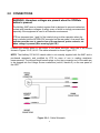
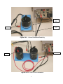
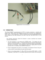
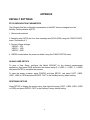
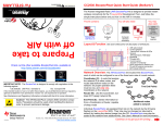
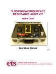
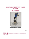
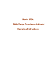
RESISTANCE/CURRENT METER
Model 863/6487
BASIC OPERATING INSTRUCTIONS
6/08
TABLE OF CONTENTS
1.0 GENERAL ………………………………………………………………………………. 3
2.0 CONNECTIONS ……………………………………………………………………….. 4
3.0 OPERATION …………………………………………………………………………… 7
4.0 REPROGRAMMING ………………………………………………………………….. 9
4.1 Test Voltages ……………………………………………………………….. 9
4.2 Sampling Rate ……………………………………………………………….10
APPENDIX
DEFAULT SETTINGS ………………………………………………………………………11
LIST OF TABLES
TABLE 1 Exponential Equivalents ……………………………………………………….. 3
TABLE 2 Suggested Test Voltages ……………………………………………………… 8
LIST OF ILLUSTRATIONS
FIGURE 2.0-1 Cable Schematic …………………………………………………………. 4
FIGURE 2.0-2 Surface Resistance/Resistivity …………………………………………. 5
FIGURE 2.0-3 Volume Resistance/Resistivity …………………………………………. 6
FIGURE 2.0-4 Point-to-Point Resistance ………………………………………………. 6
FIGURE 2.0-5 2-Point Resistance ………………………………………………………. 7
FIGURE 4.1-1 Source Voltage Adjust …….………………………………………………8
2
1.0 GENERAL
The Model 863/6487 is a high-resolution programmable picoammeter containing a ±505V DC
variable voltage source. It provides an ohms function (V/I) with direct readout for utilization as
a wide range resistance meter. It provides a vacuum fluorescent display of the measured
parameters along with analog and digital (RS-232 and IEEE-488) outputs. A complete set of
detailed operating instructions is contained in the Keithley User’s Manual supplied with each
instrument.
The following instructions are limited to the set-up and measurement of resistance or
resistivity utilizing the ETS 800 series resistance/resistivity probes or test fixtures or any
other compatible probes or test fixtures. The cable supplied has been specially adapted for
direct interface with probes equipped with standard .162” banana jacks.
The Model 863/6487 when used as a resistance meter measures over the resistance range
of 0.8 ohms to 5 x 10¹⁷ ohms (by V/I calculation). Test voltage is adjustable from 0 to ±505
Volts. Selectable current limits of 2.5mA, 250uA and 25uA for the 50V and 500V ranges, with
a 25mA additional limit for the 10V range are provided. Specified measurement accuracy is
better than 0.6% between 1 x 10³ to 1 x 10¹² ohms after a one hour warm-up period. The
instrument does not use exponents in the readout of resistance, but rather, the symbols of K
for kilohms, T for terohms, etc. TABLE 1 below lists the relationship between displayed
symbols and the corresponding exponents.
Indicated Range:
Ω
KΩ
MΩ
GΩ
TΩ
PΩ
Exponential Equivalent:
100
103
106
109
1012
1015
Table 1 – Exponential Equivalents
The instrument is preprogrammed at ETS to provide the most common measurement
parameters required in current EOS/ESD, EIA, ASTM and Military Standards and
specifications. If other test voltages or sampling intervals are desired, the procedures for
reprogramming these parameters are contained in SECTION 4.0 - REPROGRAMMING.
3
2.0 CONNECTIONS
WARNING: Hazardous voltages are present when the OPERate
button is pressed.
The Keithley 6487 uses an interlock system that is designed to prevent inadvertent
contact with hazardous voltages. A safety cover or fixture is strongly recommended,
especially if the equipment is used in a Production environment.
ETS has jumpered pins 1 and 2 of the interlock plug to allow operation when the
plug is inserted into the INTERLOCK connector on the rear panel. As a result, the
operator must be sure to remain clear of the equipment, probe contacts, etc.
when voltage is present (Blue warning light ON.)
Connect the desired probe or test fixture to the Model 863/6487 using one of the setups
shown in Figures 2.0–2,3,4 & 5. The cable schematic is shown Figure 2.0-1.
NOTE: The Keithley 237-ALG-2 triaxial cable is not normally supplied with the 6487 and is
purchased separately and modified by ETS for ease of use in making resistance
measurements. The red and black banana plugs on the triax connector end of the cable are
to be plugged into the Voltage Source connectors (red=HI, black=LO) on the rear panel of
the 6487.
Figure 2.0-1: Cable Schematic
4
Ground Plane
To external
Ground
connection
Ground Plane is used when measuring insulative materials per ASTM D257
Insulating
Plane
Insulating Plane is used when measuring static dissipative materials per ESD S11.11
Figure 2.0-2: Surface Resistance/Resistivity
5
Conductive
Plane
Insulated
Plane
V-Source
Ground
Figure 2.0-3: Volume Resistance/Resistivity
Sense
Not connected
V-Source
Red cable
supplied with
Model 850
Figure 2.0-4: Point-to-Point Resistance
6
Figure 2.0-5: 2-Point Resistance
3.0 OPERATION
The Model 863/6487 is preprogrammed at ETS to measure resistance or resistivity with
either a 10V, 100V or 500V test voltage by selecting one of the three user configurations,
USR0, USR1 or USR2 respectively. (USR0 is programmed as the power-up default setting.)
Other voltages can be easily selected by the user at any time. See SECTION 4.0 of this
manual.
The following instructions should be followed to ensure consistent and accurate
resistance measurements:
1. Turn the instrument on by pressing the POWER switch. The display will cycle
through a self-check program. It is recommended that the instrument be allowed to
warm up for one hour prior to use. However, the instrument can be used immediately
after turn on if necessary. If the instrument is used on an ongoing basis the power
should be left on in standby mode (OPERATE switch off.)
2. Place the appropriate test probe on the sample to be measured. Ensure that good
surface contact is made between the probe and the sample.
3. Select a test voltage of either 10, 100, or 500V by selecting USR0, USR1, or USR2
respectively. (Press SETUP, use RANGE up/down arrows to select USR, then press
7
ENTER.) The instrument is defaulted at the factory for USR0 (10V). See Section 4.1
for selecting other test voltages.
4. To begin a test and take a reading, press the OPER push button. A blinking dot on
the display will flash each time a sample is taken at an approximately six (6) second
sampling rate that is preset by ETS. If another sampling rate is desired, refer to
Section 4.2 for resetting the RATE value.
AUTORANGE is enabled as the default. With AUTORANGE enabled (AUTO
indicator on), the instrument will automatically adjust to the correct measuring range.
Occasionally, it may be necessary or desirable to utilize manual ranging. When using
manual ranging, choose an appropriate range value based on the voltage source
setting and the expected measured resistance: I=V/R. Press either the ▼ or ▲
range pushbuttons to select the desired range. This will automatically disable the
AUTORANGE mode. (Note: The resistance range selected is not shown on the
meter, only the current range is displayed.)
To reinstate AUTORANGE, press the AUTO pushbutton. The AUTO indicator will
light on the display.
NOTE:
When measuring low resistances, the test voltage must be reduced so
that the set maximum current is not exceeded. When this level is
exceeded, the display will indicate OVRFLOW (overflow) or I-LIMIT. To
determine the maximum voltage that can be used, calculate:
V = IR.
= (25x10-3) R
or
= (2.5x10⁻³) R
(10V or less)
(>10V)
The lowest resistance that can be measured is 0.8 ohms. TABLE 2
lists the suggested voltages for different minimum resistances.
Resistance Range: (Ω)
Test Voltage: (Volts)
0.5
5
50
500
5K
50K
250K
0.01
(25mA)
0.10
|
1.00
|
10.00
|
10.00 (2.5mA)
100.00
|
500.00
|
Table 2 – Suggested Test Voltages
8
5. There is a delay while the instrument measures and calculates the next displayed
value. In addition, there may be an additional delay due to electrification of the
material. This is a charging effect and will depend on the material being measured. It
is more noticeable at the higher resistance ranges. Continue the test until the
readings appear to stabilize. At the conclusion of the test, turn off the voltage source
by pressing the OPER pushbutton (blue warning indicator off). This returns the
instrument to the standby mode.
NOTE:
The Model 863/6487 reads only measured resistance. Resistivity
probes and test fixtures that have multiplication factors such as the
ETS Model 803B (x10 built-in), must have these multiplication factors
applied to the displayed reading to convert resistance to resistivity.
4.0
REPROGRAMMING
The Model 863/487 is preprogrammed at the factory to enable the user to immediately place
the instrument into service as a precision wide range resistance meter, meeting most
common resistance and resistivity test specifications.
This section covers reprogramming the instrument to default to other test voltages and
sampling rates. Refer to the Keithley manual for information on reprogramming other
parameters.
4.1 Test Voltages
Open circuit test voltages from 0 to 505 Volts can be selected by the user. The new
values will remain in memory until they are either changed or the instrument is turned
off.
Press either of the VSOURCE up/down arrows to enter the voltage adjustment mode.
Then press either the ◄ or ► pushbuttons to move the cursor (flashing digit). Each
digit may then be changed individually by pressing the ▲ or ▼ pushbuttons under VSOURCE until the correct value is obtained. Repeat this sequence until all of the digits
are set to the desired level then press ENTER.
If the current limit prompt appears, in most cases you may skip it by pressing EXIT
after adjusting the voltage.
9
Figure 4.1–1: Source Voltage Adjust
4.2 Sampling Rate (TRIGGER INTERVAL)
The sampling rate (RATE) is set by ETS for the maximum sampling rate (NPLC:60.00) using
the CONFIG RATE menu. This presents a more stable display when making high resistance
measurements. The sampling rate is expressed in terms of the Number of Power Line Cycles
(NPLCs). See page 4-4 of the Keithley Manual for a detailed explanation.
There are two ways of changing the sampling rate:
Press the RATE key to select SLOW, MED (Medium) or FAST
or
Press the CONFIG then RATE keys to enter the desired number of power line cycles
(NPLCs) between samples. To convert into time: One power line cycle at 60Hz = 16.66 ms;
50Hz = 20 ms. This number can range from 0.01 to 60 for 60Hz or 0.01 to 50 for 50Hz
power. The arrow keys are used for entering the number in the same manner as described in
section 4.1 for adjusting source voltage.
10
APPENDIX
DEFAULT SETTINGS
ETS CONFIGURATION PARAMETERS
The following lists the configuration parameters in the 6487 that are changed from the
Keithley Factory defaults by ETS:
1. Ohms mode selected
2. Sampling rate (RATE) set for a slow sampling rate (NPLC:60.00) using the CONFIG RATE
menu. See section 4.2
3. Source Voltage settings:
USER0 – 10V
USER1 – 100V
USER2 – 500V
4. USER0 is selected as the power on default using the CONFIG SETUP menu.
SAVING USER SETUPS
To save a User Setup, configure the Model 863/6487 for the desired measurement
application, then press SAVE and select the desired setup (0 = USR0, 1 = USR1, 2 = USR2)
and press ENTER to complete the process.
To save the power on-setup, press CONFIG and then SETUP, and select FACT, USR0,
USR1, USR2 or GPIB and press ENTER. FACT is the Keithley factory default setting.
RESTORING SETUPS
Press SETUP to display the restore menu, then select the setup (FACT, USR0, USR1, USR2
or GPIB) and press ENTER. FACT is the Keithley Factory default setting.
11