1
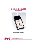
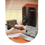
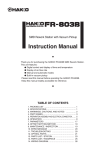
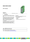
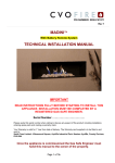
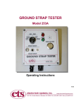
RESISTANCE/RESISTIVITY PROBE
SYSTEM
Model 823-847
Operating Instructions
5/09
1.0 DESCRIPTION
The Model 823-847 Resistance/Resistivity Probe System incorporates an ETS Series
800 Resistance Probe mounted in a press to provide controlled force to the sample
under test to measure surface and/or volume resistance (optional volume resistance
metal plate electrode required). A 6” (152mm) sq. acrylic plate is attached to the base of
the press, using Velcro to provide the insulated surface specified in ESD STM11.11.
The optional 4” (102mm) sq. metal electrode is placed on top of the acrylic plate to
provide either the guard specified in ASTM D257 or become the bottom electrode to
measure volume resistance.
Resistivity is calculated from the measured resistance using the geometry of the specific
electrode configuration. Figure 1.0-1 shows a standard Model 823-S4F probe with an
array of spring-loaded flat electrodes, designed to measure the surface resistance of
non-flat surfaces. When configured with S4K or S4B pointed electrodes as shown in
Figure 1.0-2 and mounted into the press, the Model 823-823-S4K-847 System is
capable of measuring the resistance of both the outer layers and an adjacent buried
conductive layer of penetrable, multi-layer material such as ESD safe paperboard.
Other configurations may include the ETS Model 803B or the Model 850 Resistance
Probes. With the appropriate adapters the System can be configured to accommodate
other probe designs such as the ETS Series 840 Resistance Probes.
Figure 1.0-1: Model 823 Resistance/Resistivity Probe
ETS Probes are based on the concentric ring electrode configuration specified in ASTM
D 257, IEC Publication 93 (1980), ESD Association ESD STM11.11 (Surface
Resistance) and STM11.12 (Volume Resistance) and other similar resistance/resistivity
standards. The geometric design of the concentric rings normally provides a surface
resistivity calculation equal to 10x the measured resistance (Rm). Volume resistivity is
calculated using the center electrode geometry (A=area of electrode cm2) and the
thickness (t cm) of the sample
ρv = a/t Rm Ohms-cm.
The Model 823 is a modified Model 803B Probe configured with an array of 54 springloaded electrodes instead of the specified solid conductive rubber electrodes. The 2.5”
outer and 1.2” inner diameter electrodes plus a weight of 5 pounds meet the
requirements of ESD STM11.11 and STM11.12, the electronics industry standards for
measuring surface and volume resistance of planar materials. For many materials, the
2
measurements obtained with the Model 823 correlate very closely with measurements
taken with the standard Model 803B.
The Model 850 is a 2.5” diameter solid electrode Probe that can be used to measure
volume resistance.
Figure 1.0-2: Model 8200-823-S4K Surface Resistance Measuring System
The Model 823 consists of an outer ring of thirty-six (36) and an inner ring of eighteen
(18) equally spaced spring-loaded electrodes. The diameter of the standard flat
electrode is 0.156” (3.96mm) and the force required to fully compress a single electrode
is 5 oz. (140 g). Therefore, the total force required to fully compress all of the electrodes
is approximately seventeen (17) pounds (7.6 kg).
The electrodes are installed into individual sockets to facilitate replacement when
required. Available electrode configurations for the Model 823 Probe are shown in
Figure 1.0-3.
Conductive rubber
Figure 1.0-3: Available electrode configurations
3
For those applications where it is desired to penetrate deeper into the test material it is
suggested that the S4B pin configuration be used.
2.0 SET UP
The Model 8200 System can be used with any resistance meter that has standard
banana cable connections and meet the range and accuracy requirements specified for
the measurement. ETS can provide standard or custom adapters to for use with meters
having different connectors or cables.
The Model 823 Probe and press are shipped separately. The basic press adjustments
are preset at the factory. The press incorporates an aluminum adapter that screws on to
the ¼-20 treaded stud located on the top of the Probe. The press is shipped
disassembled and requires the user to install the press assembly onto the base and
attach the Probe.
To install the press assembly onto the base place it into the hole located at the rear of
the base and secure it by tightening the hex nut sufficiently so the assembly does not
rotate.
To install the Model 823 Probe onto the press remove the wrench located at the rear of
the press assembly under the retaining knob. Place the wrench on the nut shown in
Figure 2.0-1 and screw the Probe in until it is tight. Replace the wrench so it does not
get misplaced.
If using the ETS Series 840 Probes, shown in Figure 2.0-2 the adapter will incorporate a
BNC connector to which the probes will be attached.
Model 841 is a .875” (2.2 cm) diameter concentric ring
Probe with a single .156” (.4 cm) diameter center
electrode and 7, .100” (.25) diameter outer electrodes on
.438” (1.1 cm) centers. Minimum measurement size is a
.5” (1.3 cm) diameter surface with a .438” (1.1 cm) deep
cavity.
Model 842 is a 1.5” (3.8 cm) diameter concentric ring
Probe with an inner ring of 5, .156” (.4 cm) electrodes and
an outer ring of 17, .156” diameter outer electrodes on
.875” (2.2 cm) centers. Minimum measurement size is
1.25” (3.2 cm) with a .25” (.64 cm) deep cavity.
Model 844 is a .875” (2.2cm) diameter 2-point Probe with
2, .156 (.4 cm) diameter electrodes spaced .25” (.64 cm)
between centers. Minimum measurement size is .75” x
.188” (1.9 x .48 cm) with a .438 (1.1 cm) cavity.” Also
available with .125: dia. conductive rubber electrode tips.
4
Model 845 is a 2.5” (6.4 cm) diameter single point Probe
with the standard conductive rubber electrode. Electrode
resistance is less than 100 Ohms. It is a 1 lb (2.2 kg)
version of the ESD Assoc. S4.1 and NFPA specified 5 lb
Probe.
Figure 2.0-2: Series 840 Probes
Vertical adjust knob
Hex nut
Figure 2.0-1: Installation of Probe onto press assembly
Plug the cables into the respective banana jacks and secure to the mounting slots as
shown in Figure 2.0-3. As an example, the cable from the ETS Model 871 is shown
snapped into the slots. Cables from other meters may have to be secured differently
With the press handle in the full up position and the assembly at maximum height, the
tips of the electrodes are approximately 1” (25mm) above the acrylic test bed. To adjust,
loosen the knob holding the press assembly to the vertical shaft and reposition as
necessary. This is the basic setting and may be necessary to readjust to compensate
for sample thickness.
Figure 2.0-3: Complete test set-up
5
3.0 OPERATION
3.1
Surface Resistance
For surface resistance measurements the red jack or plug is connected to the
outer ring and should be connected to the V-Out or red connector on the meter.
The black jack or plug is connected to the inner ring and should be connected to
the SENSE or black connector on the meter. The GROUND jack or plug is
connected to the meter ground via the green banana plug. If the meter does not
have a ground connection, then leave the green banana plug loose. If the V-Out
and SENSE connections are not defined then plug the banana plugs into the
resistance meter jacks.
To make a surface resistance measurement using the standard Model 823
Probe, simply place the sample on the acrylic surface and apply sufficient
pressure to compress the spring-loaded electrodes approximately half way as
shown if Figure 3.1-1. When measuring non-planar materials the spring travel of
each electrode will compensate for both non-perpendicular placement of the
probe and uneven test surfaces. For uneven surfaces apply sufficient additional
pressure so that all electrodes are at least partially compressed. Approximately
10 pounds (4.5 kg) of force should be sufficient to partially compress all the pins.
To make a measurement with the Model 823-S4K or S4B Probe different levels
of force may be required depending upon the surface being measured. When
measuring the outside layers of a planar material 5 lbs of force (weight of the
Model 823 Probe) should, in most cases, be sufficient to provide stable
measurements. To measure a buried layer it is necessary to apply enough
additional force on the Probe to both fully compress the electrodes and to
penetrate the outer layer.
Figure 3.1-1: Applying pressure
When the handle is pulled down all the way the electrode pins should be fully
compressed when a test sample is in place and measurement of the buried layer
is desired.
6
NOTE:
The resistance of the buried layer must be lower than the resistance of the outer
layer that is being penetrated. Sufficient force will have to be applied to ensure
that the pins penetrate the outer layer and make total contact with the buried
layer. Be careful not to apply excessive force.
To measure just the outer layer, apply just enough force for the pointed pins to
make contact with the surface. Be careful not to apply too much force as this may
cause the pins to penetrate the outer layer.
3.2
Volume Resistance
The Models 823-S4F and 850 Probes can also be used to measure volume
resistance. The center ring of electrode pins remains connected to the SENSE
input of the resistance meter. The VE output of the resistance meter is connected
to the metal plate electrode that is placed on top of the acrylic plate. The
resistance is then measured through the material.
The volume resistivity is calculated by multiplying the measured resistance by the
surface area of the SENSE electrode divided by the thickness of the material. For
these probes, the area used in the calculation is the number of center pins times
the area of each pin in centimeters. The area of each pin is 0.123cm2. Therefore,
the total measuring area used in the calculation for the Model 823 is 18x.123 =
2.22cm2. For the Models 804 and 850 the area of the center electrodes is 0.85
and 31.9 cm2 respectively.
3.3
Using Model 823 without the Model 847 Press
To use the Model 823 without the Press simply remove the Probe from the press
assembly. A spare handle is included. Simply screw it onto the ¼-20 stud
protruding from the top of the Probe. Tighten sufficiently so that the handle lines
up parallel to the input banana jacks.
3.4
Using Models 803B & 850 Resistance Probes with the Model 847
The Model 847 Press can also be used with existing ETS Model 803B and 850
Probes. For the Model 803B, place the probe on the sample and lower the
handle until the aluminum adapter fitting touches the top of the handle as shown
in Figure 3.4-1. Then apply additional force necessary to obtain a stable reading.
This configuration is very helpful in obtaining stable measurements when the
planer test sample is not totally flat such as sample test plaques.
If using the Model 850 Probe it will be necessary the remove the aluminum
adapter fitting. It will be necessary to grip the fitting with a pair of pliers and
rotating the nut using the supplied wrench
7
Figure 3.4-1: Using Press with Model 803B Probe
4.0 MAINTENANCE
The standard Model 823 should not require any service if care is exercised in its use.
However, if one or more spring-loaded contacts become damaged or if the pointed pins
become dull, they can be easily replaced by taking a small needle nose pliers to remove
them. Replacement contacts are available from ETS and are installed simply by
inserting them into the socket and then pushing them in all the way in. Use a piece of
wood or other relatively soft material to insert the pointed pins.
5/09
8
5.0 WARRANTY
Electro-Tech Systems, Inc. warrants its equipment, its accessories and parts of its
manufacture to be and remain free from defects in material and workmanship for a
period of one (1) year from the date of invoice., ETS will, at it’s discretion, either replace
or repair without charge, F.O.B. Glenside, similar equipment or a similar part to replace
any equipment or part of its manufacture which, within the above stated time, is proved
to have been defective at the time it was sold. All equipment claimed defective must be
returned properly identified to the Seller (or presented to one of its agents for
inspection). This warranty only applies to equipment operated in accordance with
Seller's operating instructions.
Seller's warranty with respect to those parts of the equipment that are purchased from other
manufacturers shall be subject only to the manufacturer's warranty. The Seller's liability
hereunder is expressly limited to repairing or replacing any parts of the equipment manufactured
by the manufacturer and found to have been defective. The Seller shall not be liable for
damage resulting or claimed to result from any cause whatsoever.
This warranty becomes null and void should the Resistance/Resistivity Kit, or any part
thereof, be abused or modified by the customer of if used in any application other than
that for which it was intended. This warranty to replace or repair is the only warranty,
either expressed of implied or provided by law. It is in lieu of all other warranties and the
Seller denies any other promise, guarantee, or warranty with respect to the equipment
or accessories and, in particular, as to its or their suitability for the purposes of the buyer
or its or their performance, either quantitatively or qualitatively or as to the products
which it may produce. The buyer is expected to expressly waive rights to any warranty
other than that stated herein.
ETS must be notified before any equipment is returned for repair. ETS will issue
an RMA (Return Material Authorization) number for return of said equipment.
Equipment should be shipped in the original packaging. If this is not possible, the
equipment should be packed in a sufficiently large box of double wall
construction with substantial packing around all sides. A description of the
problem along with the contact name and telephone number must be included in
formal paperwork and enclosed with the instrument. Electro-Tech Systems, Inc.
will not assume responsibility for additional cost of repair due to damage Incurred
during shipment as a result of poor packaging.
9