1
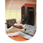
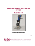
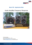
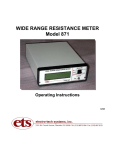
Model 870A
Wide Range Resistance Indicator
Operating Instructions
Table of Contents
1.0
Introduction
1
2.0
Equipment Description
2.1 Standard Model
Figure 2.0-1 Model 870A Wide Range Resistance Indicator
2.2 Optional Accessories and Configurations
2.2.1 Analog Meter Readout
2.2.2 Volume Resistivity
2.2.3 Surface Resistance Probe - Model 850
Figure 2.2.3-1 Model 850 Surface Resistance Probe
2.2.4 Personnel Resistance to Ground Configuration
1
1
2
3
3
3
3
4
4
3.0
Operation
3.1 Resistivity Measurements
3.1.1 Surface Resistivity Measurement Considerations
Figure 3.1.1-1 Microscopic Electrode/Rigid Surface Contact
Figure 3.1.1-2 Volume Effects in Ps Measurements
3.2 Resistance-to-Ground Measurements
Figure 3.2-1 Resistance To Ground Test Set-Up
3.3 Point-To-Point Resistance Measurements
Figure 3.3-1 Point-To-Point Resistance Measurement
3.4 Volume Resistivity
Figure 3.4-1 Measurement of Volume Resistivity
3.5 External Probe
3.6 Battery Replacement
4
4
5
5
6
7
7
8
8
8
9
9
9
4.0
Analog Meter Readout (Optional)
Figure 4.0-1 Analog Meter Module
4.1 Reading The Model 870M Meter
10
10
11
5.0
Maintenance
11
6.0
Calibration Check
Table 1 Calibration Chart
12
13
1.0 INTRODUCTION
Many applications require a point-to-point surface resistance or surface resistivity measurement
to be made on a pass/fail basis. Products such as packaging material, work bench surfaces,
chair mats, floor surfaces and conductive conveyor belts have resistive properties that may vary
from less than 102 to greater than 1012 ohms. Current standards require that these products meet
specific resistance requirements.
The Model 870A Wide Range Resistance Indicator is a compact, precision instrument that
performs both resistance and resistivity measurements. Measuring accuracy in the 102 to 107
ohms range is ±2% and in the 108 to 1011 ohms range is ±5%.
It is an ideal instrument for checking the resistance/resistivity requirements specified in the ASTM
D 257, EIA-541, NFPA 99, ESD Association Standards, ASTM F150 and applicable DOD
standards.
A unique reversible electrode assembly enables the user to select either a 2.5 inch diameter
electrode or a concentric ring electrode configuration.
The Model 870A incorporates user selectable test voltages of 10 and 100 volts. In the 10 volt
range, the entire resistance range of 102 to 1011 ohms can be measured. In the 100 volt range
only the resistance range of 104 to 1011 can be measured. By having user selectable test
voltages, the instrument meets the measurements requirements specified in EOS/ESD and EIA
specifications. The Model 870A can also be used for any measurement where test voltages of 10
or 100 volts may be utilized.
2.0 EQUIPMENT DESCRIPTION
2.1
Standard Model
The Model 870A Wide Range Resistance Indicator is a compact, precision instrument that
accurately indicates the resistance and/or resistivity characteristics of material. The
instrument incorporates a unique set of electrodes that enable a single instrument to
measure point-to-point and point-to-ground resistance, surface and volume resistance and
resistivity.
The resistance electrode consists of a 2.5 inch diameter conductive silicone rubber disc
with a hardness of 65 durometer that is mounted on one side of the plug-in electrode
assembly. This electrode conforms to the requirements specified in NFPA 99, ASTM F150
and ESD Association Standards. External jacks are provided for connecting the Model
870A to a ground point or to an external probe.
The 2.5 inch diameter carbon loaded electrode has a volume resistivity of 8 ohm-cm. When
placed on a surface, the electrode adds approximately 25 ohms series resistance to the
measurement. This additional resistance must be taken into account when using the lowest
resistance range. However, current requirements usually specify a lower resistance limit of
103 to 105 ohms. At these levels, the error introduced by the electrode resistance is
negligible.
1
The resistivity electrodes consist of a concentric ring configuration where the inside
diameter of the outer electrode is 2.25 inches and the outside diameter of the solid interior
electrode is 1.2 inches. This configuration also meets the requirements specified in
surface and volume resistance ESD S11.11 and ESD DS11.12 respectively.
The ratio of the concentric rings, as specified in ASTM D257, is 10. Hence, to convert a
surface resistance measurement to a surface resistivity value only requires multpilying the
measurement by 10, Ps = 10 Rm or reading the surface resistivity directly by using the red
scale.
Figure 2.0-1
Model 870A Wide Range Resistance Indicator & Accessories
These silver impregnated silicone rubber electrodes have a volume resistivity of .01 ohmcm which adds approximately one (1) ohm series resistance to the measurement.
The Model 870A Wide Range Resistance Indicator is capable of accurately indicating
resistance in (9) decade steps from 102 to 1011 ohms using the 10 volt range. When using
the 100 volt range, the two lower resistance decades (102 to 103 ohms and 103 to 104
ohms/sq.) are made inoperable. The 100 volt power supply is turned off when these
ranges are selected.
Three LED point source readouts indicate whether the measured resistance is within the
selected range (continuous green light), under the selected range (flashing yellow light) or
over the selected range (flashing red light). A pulsating audio tone is also provided to
indicate out of range measurements. This tone can be switched on or off by the user.
The Range Select switch has two scales. The black scale covers the nine (9) decade
resistance range from 102 to 1011 ohms. The red scale covers the nine (9) decade
resistivity range from 103 to 1012 ohms/square.
2
The total probe weight of the Model 870A is 5 pounds as required by applicable
specifications. The unit measures only 5.25”W x 3.0”D x 6.50”H including the convenient
carrying handle.
The instrument is powered by two (2) standard 9 volt alkaline batteries (Duracell MN1604 or
equivalent). A built-in battery low detection circuit automatically indicates when the
batteries are near the end of useful life.
2.2
Optional Accessories and Configurations
2.2.1
Analog Meter Readout
An optional plug-in module with a 2.5 inch analog meter is available to convert the
Model 870A Wide Range Resistance Indicator to a Wide Range Resistance Meter.
The face of the meter contains a three (3) decade scale that is colored in yellow,
green and red, corresponding to the UNDER, PASS and OVER Range LED
indicators. The UNDER and PASS scales are calibrated to measure resistance
with two (2) digit precision. The addition of the analog meter also expands the
overall range of the Model 870A to a resistance range from 10 to 1 x 10¹² ohms and
to a resistivity range from 1 x 10² to 1 x 10¹³ ohms/square.
2.2.2
Volume Resistivity
Volume resistivity may be calculated from the measurement of the resistance
through a known thickness of material. The Model 870A can be used to measure
this resistance; thus, an accurate calculation of its volume resistivity can be made.
The ASTM D 257 formula for volume resistivity, Pv, can be used to calculate the
volume resistivity as follows:
Pv = A
t
Rm ohms-cm
A = Area of measuring electrode in cm2
t = Thickness of test specimen in cm
Rm = Measured resistance in ohms
2.2.3
For the Model 870A the area of the 2.5 inch diameter (3 cm) electrode is 31.67
cm2, hence,
Pv = 31.67 Rm ohms-cm
t
Surface Resistance Probe - Model 850
To accurately measure the point-to-point resistance of a flat surface requires a
second circular probe whose weight, size and hardness are identical to the circular
electrode in the Model 870A.
The Model 850 Surface Resistance Probe is designed to meet these requirements
as well as those set forth in NFPA 99, ASTM F150 and ESD Association
Standards. The overall dimensions of the Model 850 Probe are 2.75 inches in
diameter and 5.375 inches high, including the handle. The Probe has a weight of
5.0 pounds and contains a 2.5 inch diameter silicone rubber electrode having a
hardness of 65 durometer and as shown in Figure 2.2.3-1.
3
Figure 2.2.3-1
Model 850 Surface Resistance Probe
2.2.4
3.0
Personnel Resistance to Ground Configuration
The Model 870A can be used to accurately measure the resistance-to-ground of
personnel grounding systems such as wrist and heel straps, conductive footwear,
etc. A personnel resistance to ground configuration can be assembled by the user
by using the 2.5 inch diameter electrode and placing the Indicator on an isolated
Test Bed and connecting the external output to ground. Touching the metal plate
will then give an accurate indication of the resistance to ground of the test subject.
WARNING: This test should be performed at a test voltage of 10 volts. Using 100
volts may present a shock hazard.
OPERATION
The Model 870A Wide Range Resistance Indicator is an easy to use instrument for checking the
resistive characteristics of material on a pass/fail basis. The instrument consists of four (4)
controls: POWER, AUDIO, RANGE SELECT and TEST VOLTAGE. The POWER switch turns
the unit on, which is indicated by one of the RANGE LEDs illuminating. The AUDIO switch
enables the user to disable the pulsating out-of-range audio indicator. The RANGE SELECT
switch determines which resistance/resistivity decade will be indicated by the PASS indicator.
The TEST VOLTAGE select switch determines which test voltage is being used for the
measurements. The measurement capability of the instrument is disabled when the 102 to 103
ohm or the 103 to 104 ohm/sq. ranges are selected with the TEST VOLTAGE set at 100 volts.
3.1
Resistivity Measurements
The Model 870A can measure the surface resistivity of virtually any homogeneous, flat
surface that is at least 2.75” in diameter.
Select the concentric ring electrodes of the electrode assembly by plugging the assembly
into the three (3) banana jacks located on the acrylic plate.
Turn the POWER switch to ON and select the desired TEST VOLTAGE. Set the RANGE
SELECT to the desired PASS range. If a specific resistance/resistivity is not specified or
4
known, then just place the Indicator firmly on the test surface and wait at least 10 seconds
before taking a reading. A PASS indication will indicate that the measured resistivity is
within the decade range selected. A yellow or red indication will indicate the measurement
is below or above the selected decade. Rotate the RANGE SELECT until a green PASS
indication is obtained. Check the range selected. The measured resistivity will be
accurately indicated as being within that decade.
The pulsating audible tone will sound whenever the indicated resistivity is either over or
under the selected decade range. The tone can be disabled by the user if desired by
placing the AUDIO switch in the OFF position.
3.1.1
Surface Resistivity Measurement Considerations
For most film and foam materials the standard 5 pound weight of the Model 870A
Indicator is sufficient for the electrodes to make total contact with the material
surface. However, for rigid materials such as table tops, plastics, cardboard, etc,
additional force which will have to be determined by the user, may have to be
applied to the Indicator to ensure total contact. Microscopically, these surfaces are
generally not smooth and are uneven as illustrated in Figure 3.1.1-1.
In most cases the application of additional pressure will cause the measured
resistance reading to decrease. This is a result of both lower contact resistance
and the total electrode/surface contact area (greater number of parallel resistance
paths). Optimum contact pressure is obtained when the resistance/resistivity
indication is stable.
Another area that must be considered when attempting to make a surface
resistivity measurement is the composition of the material being evaluated. The
materials defined in ANSI/ASTM D-257 are homogeneous, insulating types.
However, in many specifications the materials are nonhomogeneous and relatively
conductive. A surface resistance measurement in accordance with ESD S11.11
should be used for these materials.
Figure 3.1.1-1
Microscopic Electrode/Rigid Surface Contact
5
The surface resistivities of materials having relatively low volume resistivities
cannot be easily measured because the volume and surface resistivities interact.
The current path between the electrodes is not only across the top surface but also
through the material. Therefore an ESD 11.31 surface resistance measurement
should be made.
Similarly, the surface resistivities of materials that are coated with, or laminated to,
a conductive surface cannot be measured. The surface resistance may actually be
very high but the volume resistance may be relatively low. Therefore, the
measured resistance may be that of the surface resistance path between the
electrodes in parallel with the series combination of the two volume conductive
paths and the conductive layer as shown in Figure 3.1.1-2.
Another material type is the composite. These materials generally consist of a
high resistance resin loaded with conductive fibers. The surface resistivities of
these materials is essentially nonmeasurable. What is actually being measured is
the net resistance of the series/parallel combination of the conductive fibers
connecting the parallel bar electrodes.
Another very important consideration in measuring surface resistance/resistivity is
the time of electrification. This is the time for the effective capacitance of the
material to charge up. At this time, the current flow through the material reaches
steady state and its flow is then a function of only the resistance of the material.
Effective material capacitance is generally quite low. For low resistance materials,
the RC time constant, T, is very short. On the other hand, for high resistance
materials the time constant can become quite long.
Figure 3.1.1-2
Volume Effects in Ps Measurements
6
Resistances that are measured before the full time of electrification has occurred
will appear to be lower than the actual resistance of the surface. This difference
can be several orders of magnitude. ASTM D 257 recommends a time of
electrification of 60 seconds, but in many measurements a shorter time may be
used or a longer time may be required. Usually for small sample specimens with
resistances less than 1012 ohms, an electrification time of 10 to 15 seconds is
sufficient. On the other hand, with large surfaces such as table tops the
capacitance is relatively large and 60 seconds may not be long enough. Here the
user may either wait for the complete electrification to obtain a true resistance
measurement or specify the measurement at the 60 second electrification time
point for a relative resistance measurement. A rule of thumb, “When in doubt,
allow more time than less time!”
3.2
Resistance-to-Ground Measurements
Select the resistance electrode by unplugging the electrode assembly and inverting it to
expose the 2.5 inch diameter electrode. Connect the 5 foot red banana-to-banana cord to
the RED EXT PROBE banana jack located on the side of the unit. Connect the other end
to the groundable point using either the banana plug or the alligator earth clip adapter
supplied. See Figure 3.2-1.
Turn the POWER switch to ON and select the desired range.
Place the instrument firmly on the test surface and wait at least ten (10) seconds (or allow
enough time for electrification) before reading the Indicator. Rotate the selector switch until
the green PASS LED lights.
Since the 5 pound weight of the Indicator provides the specified contact pressure, no
additional pressure should be applied. The effects of electrification time discussed in
Section 3.1.2 should also be observed when making the resistance-to-ground
measurement particularly if the resistance range is above 1010 ohms.
Figure 3.2-1
Resistance To Ground Test Set-Up
7
3.3
Point-To-Point Resistance Measurements
Follow the procedure outlined in Section 3.2 for resistance-to-ground measurements
except connect the RED EXT PROBE cable to a Model 850 Surface Resistance Probe as
shown in Figure 3.3-1 below.
Figure 3.3-1
Point-To-Point Resistance Measurement
Place the Model 870A and the Model 850 at the required separation and take the
measurement as described in Section 3.2
3.4
Volume Resistivity
Select the 2.5 inch electrode as described in Section 3.1. Connect the isolated Test Bed
(optional accessory) to the RED EXT PROBE output jack located on the side of the Model
870A as shown in Figure 3.4-1. The volume resistance will be made between the 2.5 inch
diameter electrode and the isolated Test Bed as described in ESD 11.12 for volume
resistance and ASTM D257 for volume resistivity. The 1.2 inch inner electrode cannot be
used for volume resistance because the outer electrode is always connected to the
measuring system.
8
Figure 3.4-1
Measurement of Volume Resistivity
Turn the POWER switch to ON and select the desired range.
Place the test sample on the isolated Test Bed and then place the Model 870A Indicator
on top of the sample. The indicated resistance range will be the volume resistance of the
sample. To obtain the volume resistivity, the thickness of the test sample must be
measured. The volume resistivity may then be calculated as follows:
Pv = 31.67 Rm ohms - cm
t
If a non-metric measuring instrument is used, the measurement must be converted to cm.
Note: 1 mil = 2.54 x 10⁻³ cm
3.5
External Probe
The Model 870A has external banana jacks to accept other resistance measuring probes
having a 2-wire input (Voltage (Red) and Sense (Black)) such as the ETS Models 821,
822 and 824.
3.6
Battery Replacement
The Model 870A Indicator uses two (2) standard 9 volt alkaline batteries. A Battery Low
circuit is built into the instrument to warn the user when the batteries are approaching the
end of their useful life.
1.
When the battery voltage drops below 13 volts the BAT LO indicator will light. When
the battery voltage drops below the minimum voltage for specified operation the
instrument will shut down completely. No LED indicators will illuminate and no audible
tone will sound.
2.
UNDER or OVER range signals will flash more rapidly than normal.
9
3.
4.
Audible beep tone signal rate will increase.
Beep tone will become erratic or will produce a characteristic “squeal”.
5.
The unit will shut down completely.
To replace the batteries, remove the right side panel by loosening the 6-32 captive screw.
The batteries are located between the printed circuit board and the solid brass chassis.
When replacing the batteries be careful to dress the wires along the side panels so that
they do not become pinched when the side panel is replaced. Replace with the Duracell
MN 1604 or equivalent.
4.0 ANALOG METER READOUT (Optional)
The optional Analog Meter Readout converts the Model 870A Wide Range Resistance Indicator
to a Wide Range Resistance Meter. The readout module plugs into the METER jacks provided
on all Model 870A Indicators.
To install the meter module slip the notched portion of the meter module bracket over the banana
jack and then push the module downward so that the entire assembly fits over the raised side
plate as shown in Figure 4.0-1 below.
Tighten the thumb screw jack to secure the meter module to the instrument.
The complete instrument is now a precision Wide Range Resistance Meter. The scales on the
meter face are color coordinated with the range indicators on the Model 870A. The green scale
on the meter corresponds to the range selected using the RANGE SELECT knob on the 870A.
The yellow scale corresponds to the decade below the selected range and the red scale
corresponds to the decade above the selected range. Since the red over range scale is highly
compressed, only the yellow and green scales should be used to obtain accurate resistance
readings.
Figure 4.0-1
Analog Meter Module
10
4.1
Reading the Model 870M Meter
The resistance or resistivity readings obtained from the Model 870M must be added to the
range multiplier obtained from the setting of the 870A RANGE SELECT switch. For any
measurement, the Model 870M provides the numerical part of the reading and the RANGE
SELECT switch pointer on the Model 870A provides the decaded multiplier according to the
following:
Resistance or Resistivity = N x 10x
where N is the reading obtained from the Model
870M and switch setting of the Model 870A
Examples:
1. The resistance (point-to-point) of a surface is measured and the Model 870A Range
Select switch is rotated until a green (PASS) indication is obtained. The Model 870M
reading is 2.6 and the RANGE SELECT switch setting required to obtain a green
(PASS) indication is the 104 to 105 ohm range (black). The point-to-point resistance
measurement is then 2.6 x 10⁴ ohms.
2.
The resistivity of a “pink poly” material is measured and the Model 870A RANGE
SELECT switch is rotated until a green (PASS) indication is obtained. The Model
870M reading is 4.5 and the RANGE SELECT switch setting required to obtained a
green (PASS) indication is the 1010 to 1011 ohms per square range (inner [red] scale on
the Model 870A). The surface resistivity measurement is then 4.5 x 10¹⁰ ohms per
square.
3.
Same as number 2 above except the RANGE SELECT switch is set to the 1011 to 1012
ohms per square range, yellow (UNDER) light is flashing and the Model 870M is
indicating a .45 in the yellow region. The surface resistivity measurement is .45 x 1011
ohms per square. This is the same resistivity reading as was obtained in number 2
since .45 x 1011 = 4.5 x 10¹⁰ (ohms per square).
In general, readings should only be taken using the yellow scale between .1 and 1.0 or the
green scale between 1.0 and 10. Readings below .1 or above 10 (red region) should be
avoided since the 870A/870M system is not designed to provide accurate readings in these
regions.
5.0
MAINTENANCE
The Model 870A Wide Range Resistance Indicator is a ruggedly constructed and reliable
instrument but should be handled as you would any precision laboratory test equipment. The
alignment of the electrodes is critical to ensure total surface contact. The silicone rubber contact
material is impregnated with silver (resistivity electrodes) or carbon (resistance electrode). The
user must ensure that the contact area is clean and free of contaminants prior to making a
measurement. Also, the electrodes should not be exposed to atmospheres or surfaces that may
corrode the silver particles. If exposure is necessary, the contacts should be cleaned with
isopropyl alcohol immediately after use.
11
When not in use, the instrument should be kept in its carrying case (optional) or on a flat smooth
surface. The electrodes should never be kept on a sharp or protruding object since this may
damage or put a set in the silicone rubber.
If the rubber electrodes are damaged or the instrument fails to operate properly, the unit must be
returned to Electro-Tech Systems for repair.
6.0
CALIBRATION CHECK
To verify the performance of the Model 870A and to check the calibration of each range, a test
set-up utilizing a total of twenty (20) resistors of different values is required. Table 1 lists the
resistor values required to check the calibration of each range.
An incorrect indication of a particular resistor value tested in the appropriate range indicates that
the range is out of tolerance.
Plug the calibration resistors into the EXT PROBE banana jack located on the left-hand side of
the Model 870A. Place the Meter on an insulated surface (>1013 ohms/sq.) when performing the
calibration Test leads should be short and preferably made with Teflon insulated wire. When
measuring the higher ranges (above 107 ohms), lead dress and operator movement can affect
the measurement. Utmost care should be exercised to minimize any erroneous indications
NOTE:
The specified resistors in Table 1 are used to check the PASS/FAIL limits of the instrument.
If these resistors are not available, standard values such as 10K, 100K, 1 Meg, 10 Meg, 100
Meg ohms, etc can be used to check the accuracy of the Model 870A with the Model 870M
installed.
12
Range
1.0 x 10²
1.0 x 10³ ohms
1.0 x 10³
1.0 x 10⁴ ohms
1.0 x 10⁴
1.0 x 10⁵ ohms
1.0 x 10⁵
1.0 x 10⁶ ohms
1.0 x 10⁶
1.0 x 10⁷ ohms
1.0 x 10⁷
1.0 x 10⁸ ohms
1.0 x 10⁸
1.0 x 10⁹ ohms
1.0 x 10⁹
1.0 x 10¹⁰ ohms
1.0 x 10¹⁰
1.0 x 10¹¹ ohms
CAL Resistor Value
98 ohms
102 ohms
980 ohms
1.02K
980 ohms
1.02 ohms
9.8K
10.2K
9.8K
10.2K
98K
102K
98K
102K
980K
1.02Meg
980K
1.02Meg
9.8Meg
10.2Meg
9.8Meg
10.2Meg
98Meg
102Meg
95Meg
105Meg
950Meg
1.05Gigohm
950Meg
1.05Gigohm
9.5Gigohm
10.5Gigohm
9.5Gigohm
10.5Gigohm
95Gigohm
105Gigohm
Indication
Under Pass
Over
X
X
X
X
X
X
X
X
X
X
X
X
X
X
X
X
X
X
X
X
X
X
X
X
X
X
X
X
X
X
X
X
X
X
X
X
Table 1
Calibration Chart
13
Notes
Use ¼ watt or larger resistors
for these tests.
Allow at least 5 seconds for
indicators to stabilize.
Allow at least 5 seconds for
indicators to stabilize.
Allow at least 5 seconds for
indicators to stabilize.
Allow at least 5 seconds for
indicators to stabilize.
Allow at least 10 seconds for
indicators to stabilize.
Allow at least 10 seconds for
indications to stabilize.
Allow at least 10 seconds for
indications to stabilize.
Allow at least 10 seconds for
readings to stabilize.
WARRANTY
Electro-Tech Systems, Inc. warrants its equipment, accessories and parts of its manufacture to be and remain free from
defects in material and workmanship for a period of one (1) year from date of invoice and will, at the discretion of Seller,
either replace or repair without charge, F.O.B. Glenside, similar equipment or a similar part to replace any equipment or
part of its manufacture which, within the above stated time, is proved to have been defective at the time it was sold. All
equipment claimed defective must be returned properly identified to the Seller (or presented to one of its agents for
inspection). This warranty only applies to equipment operated in accordance with Seller's operating instructions.
Seller's warranty with respect to those parts of the equipment which are purchased from other
manufacturers shall be subject only to that manufacturer's warranty.
The Seller's liability hereunder is expressly limited to repairing or replacing any parts of the equipment manufactured by the
manufacturer and found to have been defective. The Seller shall not be liable for damage resulting or claimed to result
from any cause whatsoever.
This warranty becomes null and void should the equipment, or any part thereof, be abused or modified by the customer of
if used in any application other than that for which it was intended. This warranty to replace or repair is the only warranty,
either expressed or implied or provided by law, and is in lieu of all other warranties and the Seller denies any other promise,
guarantee, or warranty with respect to the equipment or accessories and, in particular, as to its or their suitability for the
purposes of the buyer or its or their performance, either quantitatively or qualitatively or as to the products which it may
produce and the buyer is expected to expressly waive rights to any warranty other than that stated herein.
ETS must be notified before any equipment is returned for repair. ETS will issue an RMA (Return
Material Authorization) number for return of equipment.
Equipment should be shipped prepaid and insured in the original packaging. If the original packaging is
not available, the equipment must be packed in a sufficiently large box (or boxes if applicable) of double
wall construction with substantial packing around all sides. The RMA number, description of the problem
along with the contact name and telephone number must be included in formal paperwork and enclosed
with the instrument. Round trip freight and related charges are the owner’s responsibility.
WARNING
WOODEN CRATES MUST NOT BE USED. PACKAGING OF DELICATE INSTRUMENTS IN
WOODEN CRATES SUBSTANTIALLY INCREASES THE CONTENT’S SUSCEPTIBILITY TO
SHOCK DAMAGE.
DO NOT PLACE INSTRUMENTS OR ACCESSORIES INSIDE OTHER
INSTRUMENTS OR CHAMBERS. ELECTRO-TECH SYSTEMS, INC. WILL NOT ASSUME
RESPONSIBILITY FOR ADDITIONAL COST OF REPAIR DUE TO DAMAGE INCURRED DURING
SHIPMENT AS A RESULT OF POOR PACKAGING.
14