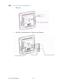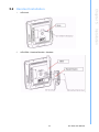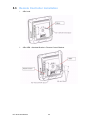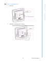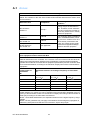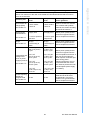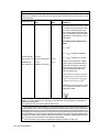
1
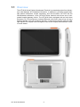
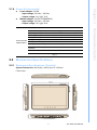
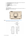
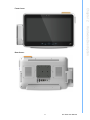
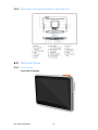
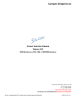
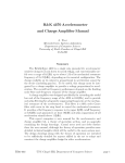
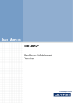
User Manual HIT-W18 Series Healthcare Infotainment Terminal Copyright The documentation and the software included with this product are copyrighted 2011 by Advantech Co., Ltd. All rights are reserved. Advantech Co., Ltd. reserves the right to make improvements in the products described in this manual at any time without notice. No part of this manual may be reproduced, copied, translated or transmitted in any form or by any means without the prior written permission of Advantech Co., Ltd. Information provided in this manual is intended to be accurate and reliable. However, Advantech Co., Ltd. assumes no responsibility for its use, nor for any infringements of the rights of third parties, which may result from its use. Acknowledgements Intel and Pentium are trademarks of Intel Corporation. Microsoft Windows and MS-DOS are registered trademarks of Microsoft Corp. All other product names or trademarks are properties of their respective owners. Declaration of Conformity FCC Class B Note: This equipment has been tested and found to comply with the limits for a Class B digital device, pursuant to part 15 of the FCC Rules. These limits are designed to provide reasonable protection against harmful interference in a residential installation. This equipment generates, uses and can radiate radio frequency energy and, if not installed and used in accordance with the instructions, may cause harmful interference to radio communications. However, there is no guarantee that interference will not occur in a particular installation. If this equipment does cause harmful interference to radio or television reception, which can be determined by turning the equipment off and on, the user is encouraged to try to correct the interference by one or more of the following measures: Reorient or relocate the receiving antenna. Increase the separation between the equipment and receiver. Connect the equipment into an outlet on a circuit different from that to which the receiver is connected. Consult the dealer or an experienced radio/TV technician for help. Warning! Any changes or modifications made to the equipment which are not expressly approved by the relevant standards authority could void your authority to operate the equipment. Caution! Danger of explosion if battery is incorrectly replaced. Replace only with the same or equivalent type recommended by the manufacturer. Dispose of used batteries according to the manufacturer's instructions. HIT-W18 User Manual Part No.2008W18100 Edition 1 Printed in Taiwan September 2011 ii Technical Support and Assistance 1. 2. Visit the Advantech web site at www.advantech.com/support where you can find the latest information about the product. Contact your distributor, sales representative, or Advantech's customer service center for technical support if you need additional assistance. Please have the following information ready before you call: – Product name and serial number – Description of your peripheral attachments – Description of your software (operating system, version, application software, etc.) – A complete description of the problem – The exact wording of any error messages Warning! 1. 2. 3. Input voltage rated 18-19 VDC, 3 A (DC Mode). Packing: please carry the unit with both hands, handle with care. Maintenance: to properly maintain and clean the surfaces, use only approved products or clean with a dry applicator. Safety Instructions 1. 2. 3. 4. 5. 6. 7. 8. 9. 10. 11. 12. 13. 14. Read these safety instructions carefully. Keep this User Manual for later reference. Disconnect this equipment from any AC outlet before cleaning. Use a damp cloth. Do not use liquid or spray detergents for cleaning. For plug-in equipment, the power outlet socket must be located near the equipment and must be easily accessible. Keep this equipment away from humidity. Put this equipment on a reliable surface during installation. Dropping it or letting it fall may cause damage. The openings on the enclosure are for air convection. Protect the equipment from overheating. DO NOT COVER THE OPENINGS. Make sure the voltage of the power source is correct before connecting the equipment to the power outlet. Position the power cord so that people cannot step on it. Do not place anything over the power cord. All cautions and warnings on the equipment should be noted. If the equipment is not used for a long time, disconnect it from the power source to avoid damage by transient overvoltage. Never pour any liquid into an opening. This may cause fire or electrical shock. Never open the equipment. For safety reasons, the equipment should be opened only by qualified service personnel. If one of the following situations arises, get the equipment checked by service personnel: a. The power cord or plug is damaged. b. Liquid has penetrated the equipment. c. The equipment has been exposed to moisture. d. The equipment does not work well, or you cannot get it to work according to the user's manual. e. The equipment has been dropped and damaged. iii HIT-W18 User Manual f. The equipment has obvious signs of breakage. 15. DO NOT LEAVE THIS EQUIPMENT IN AN ENVIRONMENT WHERE THE STORAGE TEMPERATURE MAY GO BELOW -20° C (-4° F) OR ABOVE 60° C (140° F). THIS COULD DAMAGE THE EQUIPMENT. THE EQUIPMENT SHOULD BE IN A CONTROLLED ENVIRONMENT. 16. If your computer clock loses a significant amount of time or the BIOS configuration resets to default, the battery has no power. Caution! 1. 2. 3. 4. Do not replace power adaptor yourself. Please contact a qualified technician or your retail. The computer is provided with a battery-powered real-time clock circuit. There is a danger of explosion if battery is incorrectly replaced. Replace only with same or equivalent type recommended by the manufacture. Discard used batteries according to the manufacturer’s instructions Cleaning: During normal use of the HIT-W151 may become soiled and should, therefore, be cleaned regularly. Agents: Alcohol or water. End of Product: for Environmental protection, please follow national requirements to dispose of unit. 17. CLASSIFICATION: – Supplied by Class I adapter – No applied parts – Continuous operation – No AP or APG category 18. Follow national requirements to dispose of unit. 19. Maintenance: To properly maintain and clean the surfaces, use only approved products or clean with a dry cloth. 20. Contact information: No.1, Alley 20, Lane 26, Rueiguang Road Neihu District, Taipei, Taiwan 114, R.O.C TEL: (02) 2792-7818 21. 22. This equipment is not to be used as a life support system. 23. Accessory equipment connected to the analog and digital interfaces must be in compliance with the respective nationally harmonized IEC standards (i.e. IEC 60950 for data processing equipment, IEC 60065 for video equipment, IEC 61010-1 for laboratory equipment, and IEC 60601-1 for medical equipment.) Furthermore all configurations must comply with the system standard IEC 60601-1-1. Anyone who connects additional equipment to the signal input part or signal output part is configuring a medical system, and is therefore, responsible that the system complies with the requirements of the system standard IEC 60601-1-1. The unit is for exclusive interconnection with IEC 60601-1 certified equipment in the patient environment and IEC 60XXX certified equipment out- HIT-W18 User Manual iv side of the patient environment. If in doubt, consult the technical services department or your local representative. 24. A user must not allow SIP/SOPs and the patient to come into contact with one another at the same time. 25. The sound pressure level at the operator's position according to IEC 704-1:1982 is no more than 70dB (A). DISCLAIMER: This set of instructions is given according to IEC 704-1. Advantech disclaims all responsibility for the accuracy of any statements contained herein. Caution! Use suitable mounting apparatus to avoid risk of injury. Note! Attention, please thoroughly consult the accompanying documentation. Note! Environmental protection Follow national requirements to dispose of unit. Explanation of Graphical Symbols IEC 60878 and ISO 3864-B.3.6 : Warning: dangerous voltage. ISO 7000-0434 : Attention, consult ACCOMPANYING DOCUMENTS. ISO 7000-1641 : Follow operating instructions or Consult instructions for use. IEC 60417 -5009 : SANDY-BY. IEC 60417-5031 : Direct current. v HIT-W18 User Manual Disposing of your old product Within the European Union EU-wide legislation, as implemented in each Member State, requires that waste electrical and electronic products carrying the mark (left) must be disposed of separately from normal household waste. This includes monitors and electrical accessories, such as signal cables or power cords. When you need to dispose of your display products, please follow the guidance of your local authority, or ask the shop where you purchased the product, or if applicable, follow any agreements made between yourself. The mark on electrical and electronic products only applies to the current European Union Member States. HIT-W18 User Manual vi Contents Chapter Chapter 1 Introduction..........................................1 1.1 1.2 Overview ................................................................................................... 2 System Configuration................................................................................ 4 2 Hardware Description .........................5 2.1 General Specifications .............................................................................. 6 2.1.1 Standard PC Functions................................................................. 6 2.1.2 Flat Panel Interface....................................................................... 6 2.1.3 Module Feature............................................................................. 6 2.1.4 Power Environmental.................................................................... 7 Mechanical Specifications......................................................................... 7 2.2.1 Mechanical Specifications (Terminal) ........................................... 7 2.2.2 Mechanical Specifications (Terminal with Handset) ..................... 8 2.2.3 Mechanical Drawing for Button and Rear I/O ............................. 10 External View .......................................................................................... 10 2.3.1 Front View................................................................................... 10 2.3.2 Side View .................................................................................... 11 2.3.3 Rear View ................................................................................... 12 2.2 2.3 Chapter 3 Software Description.........................13 3.1 Windows XP Embedded Software Specifications ................................... 14 4 Design Requirements........................15 4.1 4.2 Environmental Specifications .................................................................. 16 Reliability................................................................................................. 16 5 Installation..........................................17 5.1 5.2 5.3 5.4 Terminal Installation ................................................................................ 18 Handset Installation................................................................................. 19 Remote Controller Installation................................................................. 20 Arm Installation ....................................................................................... 21 Appendix A Annex..................................................23 A.1 Annex ...................................................................................................... 24 Chapter Chapter vii HIT-W18 User Manual HIT-W18 User Manual viii Chapter 1 1 Introduction This chapter briefly introduces the HIT-W18 Series product. Sections include: Overview System Configuration 1.1 Overview The HIT-W18 Series Patient Infotainment Terminal is a standard product from Advantech with Windows XP Embedded OS built-in. In addition to providing hospital bedside patient information, remote monitoring, and care functions, the CPU and the LAN-enabled architecture of the HIT-W18 Series terminal also serves as an integrated hospital gateway device. The HIT-W18 Series equipped with an Intel Atom processor, 18.5 W touchscreen, onboard Ethernet, and audio, plays a key role as a hospital bedside care and monitoring solution. It connects the service calls and LED light signals of a hospital room through the LAN to the hospital administration center or nurse station. HIT-W18 User Manual 2 Chapter 1 Introduction Note! Power LED: color in green shows power on, no color shows power off Indicator LED: It can show color in orange/green and the definitioni is controlled/defined by customer. 3 HIT-W18 User Manual 1.2 System Configuration The block diagram of a HIT-W18 Healthcare Infotainment Terminal based on Hospital bedside environment is shown in the following diagram: HIT-W18 User Manual 4 Chapter 2 2 Hardware Description This Chapter describes the hardware features of the HIT-W18. Sections include: General Specifications Mechanical Specifications External View 2.1 General Specifications 2.1.1 Standard PC Functions Category Specifications CPU Intel PineView (D525) 1.8 GHz Or SandyBridge (i7) 1.5 GHz Front Side Bus Supports FSB 800 MHz System Chipset Intel D525 + ICH8M/Intel i7 + Cougar Point Memory DDR2 667 200-pin SODIMM x 2 Storage CFAST or SATA HDD interface (Optional) Bus Expansion Mini PCIe x 2 2.1.2 Flat Panel Interface Power button: With LED indicator Audio: Mic-in, Line-out USB: USB x 3 LAN: Gigabit LAN SPK+MIC: build-in 2 x 2 W SPK + EM147 MIC Button: GPIO Programmable function Smart card reader: ISO7816 for IC card standard, PC/SC 1.0 for windows, smart card standard, Microsoft WHQL, EMV for Europay MasterCard Visa standard and USB-IF CCID standard 2.1.3 Module Feature Features Interface Description Wi-Fi Wireless Mini PCIe 802.11b&g&n RFID Kit Internal USB 13.56 MHz, ISO-15693/14443 Camera module Internal USB 2 M pixels CMOS camera LED LED module GPIO Programmable, orange light handset Handset module RJ12 Build-in SPK & MIC Remote controller RJ12 Micro controller, up to 9 keys Factory setting connector 2 Pin Connector For factory setting only, not for operator to use. port HIT-W18 User Manual 6 Chapter 2 2.1.4 Power Environmental Power adaptor: AC/DC – Input voltage: 100 Vac ~ 240 Vac – Output voltage: 19 V @ 3.79 A Medical adaptor: AC/DC (PCM80PS18) – Input voltage: 100 Vac ~ 240 Vac – Output voltage: 18 V @ 4.44 A 0 ~ 40° C Relative Humidity 10 - 95% @ 40° C non-condensing Operating Humidity 20% to 90% (No Condensation) Operating Atmospheric Pressure 700 - 1060 hPa Storage Humidity 10% - 95% (No Condensation) Storage Atmospheric Pressure Environmental Specifications Transportation Temperature Transportation Humidity 700 - 1060 hPa -20 - 60 °C 10% - 95% (No Condensation) Transportation Atmospheric Pressure 700 - 1060 hPa Vibration 1G Shock 10 G peakl acceleration (11 msec, duration ) 2.2 Mechanical Specifications 2.2.1 Mechanical Specifications (Terminal) System Dimensions: 465.9 (W) x 338.5 (H) x 51.2 (D) mm Front Cover 7 HIT-W18 User Manual Hardware Description Operating Temperature Carton Dimensions: 620 (W) x 540 (H) x 180 (D) (excludes accessories box) Mounting System: Back box for wall mounting Gross Weight: 6.1 kg Net Weight: 6.1 kg VESA Mount: 75*75 mm or 100*100 mm SCREWS: M4*10 mm IPX0 Cleaning Instruction: During normal use of the HIT-W18 may become soiled and should, therefore, be cleaned regularly. Agents: Alcohol or water. Rear Cover: 2.2.2 Mechanical Specifications (Terminal with Handset) System Dimensions: 494.5(W) x 392.2(H) x 73.5(D) mm HIT-W18 User Manual 8 Chapter 2 Front Cover: Hardware Description Rear Cover: 9 HIT-W18 User Manual 2.2.3 Mechanical Drawing for Button and Rear I/O 2.3 External View 2.3.1 Front View Front View (Terminal) HIT-W18 User Manual 10 Chapter 2 Hardware Description 2.3.2 Side View 11 HIT-W18 User Manual 2.3.3 Rear View Rear View (Terminal) HIT-W18 User Manual 12 Chapter 3 3 Software Description This Chapter describes the software features of the HIT-W18. Sections include: Windows XP Embedded Software Specifications 3.1 Windows XP Embedded Software Specifications Real-Time OS Kernel Windows XPE 7 Language Version Driver List Chipset Intel ICH8M Rev. 9.2.0.1025/Chipset Intel CougarPoint QM67 Rev. 9.2.0.1025 Graphics Intel Atom D525 Rev. 6.14.10.5080/Graphics Intel Graphics 200 Rev. 6.14.10.5298 Audio Realtek audio ALC892 Rev.5.10.0.6316 LAN Realtek RTL8111DL Rev.5.728.604.2009 Camera D-MAX 2M AF Camera Rev. 5.1.2600.5512 USB HUB NEC uPD720114GA Rev. 5.1.2600.0 Smart Card Castles EZU0030E Rev. 3.1.6.0 Touch PenMount 6000 Rev.2.1.5.103 WLAN AzureWave AW-NE768 Rev.1.4.2.1 HIT-W18 User Manual 14 Chapter 4 4 Design Requirements This Chapter describes the design requirements of the HIT-W18 Series. Sections include Environmental Specifications Reliability 4.1 Environmental Specifications Temperature & Humidity Operating Temperature: 0 ~ 40° C Storage Temperature: 0 ~ 60° C Relative Humidity: 0 ~ 95% RH (Non-condensed) Case / Panel Temperature Less than 40° C @ 25° C ambient temperature (front bezel) Safety CE EMI FCC class B approved Vibration: 10 ~ 18 Hz, 1.5 mm peak-to-peak displacement 18 ~ 500 Hz, 1 G acceleration 4.2 Reliability MTBF 80,000 hours Touchscreen 3 million touch actuation times on a single point with a 5/8" diameter silicon finger under a 350 g load at 2 Hz Power Requirements DC Input Voltage: 19 V Power Consumption: less than 75 W HIT-W18 User Manual 16 Chapter 5 5 Installation This Chapter describes the installation of the HIT-W18 Series. Sections include Terminal Installation Handset Installation Remote Controller Installation Arm Installation 5.1 Terminal Installation 1. Affix hook. 2. Affix ARM + Handset Bracket + Remote Control Bracket. HIT-W18 User Manual 18 Chapter 5 5.2 Handset Installation Affix hook. 2. Affix ARM + Handset Bracket + Handset. Installation 1. 19 HIT-W18 User Manual 5.3 Remote Controller Installation 1. Affix hook. 2. Affix ARM + Handset Bracket + Remote Control Bracket. HIT-W18 User Manual 20 Chapter 5 5.4 Arm Installation Affix hook. 2. Affix ARM + Handset Bracket + Handset. Installation 1. 21 HIT-W18 User Manual HIT-W18 User Manual 22 Appendix A Annex A A.1 Annex Guidance and manufacturer’s declaration – electromagnetic emissions The model HIT-W18 is intended for use in the electromagnetic environment specified below. The customer or the user of the model HIT-W18 should assure that it is used in such an environment. Compliance Electromagnetic environment – guidance RF emissions CISPR 11 Group 1 The model HIT-W18 uses RF energy only for its internal function. Therefore, its RF emissions are very low and are not likely to cause any interference in nearby electronic equipment. RF emissions CISPR 11 Class B Harmonic emissions IEC 61000-3-2 Class A Voltage fluctuations/ flicker emissions IEC 61000-3-3 Not applicable Emissions test The model HIT-W18 is suitable for use in all establishments, including domestic establishments and those directly connected to the public low-voltage power supply network that supplies buildings used for domestic purposes. Recommended separation distances between portable and mobile RF communications equipment and the model HIT-W18 The model HIT-W18 is intended for use in an electromagnetic environment in which radiated RF disturbances are controlled. The customer or the user of the model HIT-W18 can help prevent electromagnetic interference by maintaining a minimum distance between portable and mobile RF communications equipment (transmitters) and the model HIT-W18 as recommended below, according to the maximum output power of the communications equipment. Rated maximum output power of transmitter W Separation distance according to frequency of transmitter m 150 kHz to 80 MHz d = 1,2 P 80 MHz to 800 MHz d = 1,2 P 800 MHz to 2,5 GHz d = 2,3 P 0,01 0,12 0,12 0,23 0,1 0,38 0,38 0,73 1 1,2 1,2 2,3 10 3,8 3,8 7,3 100 12 12 23 For transmitters rated at a maximum output power not listed above, the recommended separation distance d in metres (m) can be estimated using the equation applicable to the frequency of the transmitter, where P is the maximum output power rating of the transmitter in watts (W) according to the transmitter manufacturer. NOTE 1 At 80 MHz and 800 MHz, the separation distance for the higher frequency range applies. NOTE 2 These guidelines may not apply in all situations. Electromagnetic propagation is affected by absorption and reflection from structures, objects and people. HIT-W18 User Manual 24 The model HIT-W18 is intended for use in the electromagnetic environment specified below. The customer or the user of the model HIT-W18 should assure that it is used in such an environment. Compliance level Electromagnetic environment –guidance 6 kV contact 8 kV air 6 kV contact 8 kV air Floors should be wood, concrete or ceramic tile. If floors are covered with synthetic material, the relative humidity should be at least 30 %. 2 kV for power supply lines 2 kV for powersupply lines IEC 61000-4-4 1 kV for input/output lines 1 kV for input/ output lines Surge IEC 61000-4-5 1 kV line(s) to line(s) 2 kV line(s) to earth 1 kV line(s) to line(s) 2 kV line(s) to earth <5 % UT (>95 % dip in UT) for 0,5 cycle <5 % UT (>95 % dip in UT) for 0,5 cycle 40 % UT (60 % dip in UT) for 5 cycles 40 % UT (60 % dip in UT) for 5 cycles 70 % UT (30 % dip in UT) for 25 cycles 70 % UT (30 % dip in UT) for 25 cycles <5 % UT (>95 % dip in UT) for 5 sec <5 % UT (>95 % dip in UT) for 5 sec Immunity test Electrostatic discharge (ESD) IEC 61000-4-2 Electrical fast transient/burst interruptions and voltage variations on power supply input lines IEC 61000-4-11 Power frequency (50/60 Hz) magnetic field IEC 61000-4-8 IEC 60601 test level 3 A/m 3 A/m Mains power quality should be that of a typical commercial or hospital environment. Mains power quality should be that of a typical commercial or hospital environment. Mains power quality should be that of a typical commercial or hospital environment. If the user of the model HITW18 requires continued operation during power mains interruptions, it is recommended that the model HIT-W18 be powered from an uninterruptible power supply or a battery. Power frequency magnetic fields should be at levels characteristic of a typical location in a typical commercial or hospital environment. NOTE UT is the a.c. mains voltage prior to application of the test level. 25 HIT-W18 User Manual Appendix A Annex Guidance and manufacturer’s declaration – electromagnetic immunity Guidance and manufacturer’s declaration – electromagnetic immunity The model HIT-W18 is intended for use in the electromagnetic environment specified below. The customer or the user of the model HIT-W18 should assure that it is used in such an environment. Immunity test IEC 60601 test level Compliance level Electromagnetic environment – guidance Portable and mobile RF communications equipment should be used no closer to any part of the model HIT-W18, including cables, than the recommended separation distance calculated from the equation applicable to the frequency of the transmitter. Recommended separation distance d = 1,2 P d = 1,2 P 80 MHz to 800 MHz Conducted RF IEC 61000-4-6 3 Vrms 150 kHz to 80 MHz Radiated RF IEC 61000-4-3 3 V/m 80 MHz to 2,5 GHz Vrms d = 2,3 P 800 MHz to 2,5 GHz V/m where P is the maximum output power rating of the transmitter in watts (W) according to the transmitter manufacturer and d is the recommended separation distance in metres (m). Field strengths from fixed RF transmitters, as determined by an electromagnetic site a survey, should be less than the complib ance level in each frequency range. Interference may occur in the vicinity of equipment marked with the following symbol: NOTE 1 At 80 MHz and 800 MHz, the higher frequency range applies. NOTE 2 These guidelines may not apply in all situations. Electromagnetic propagation is affected by absorption and reflection from structures, objects and people. a Field strengths from fixed transmitters, such as base stations for radio (cellular/cordless) telephones and land mobile radios, amateur radio, AM and FM radio broadcast and TV broadcast cannot be predicted theoretically with accuracy. To assess the electromagnetic environment due to fixed RF transmitters, an electromagnetic site survey should be considered. If the measured field strength in the location in which the model HIT-W18 is used exceeds the applicable RF compliance level above, the model HIT-W18 should be observed to verify normal operation. If abnormal performance is observed, additional measures may be necessary, such as reorienting or relocating the model HIT-W18. b Over the frequency range 150 kHz to 80 MHz, field strengths should be less than V/m. HIT-W18 User Manual 26 Appendix A Annex 27 HIT-W18 User Manual www.advantech.com Please verify specifications before quoting. This guide is intended for reference purposes only. All product specifications are subject to change without notice. No part of this publication may be reproduced in any form or by any means, electronic, photocopying, recording or otherwise, without prior written permission of the publisher. All brand and product names are trademarks or registered trademarks of their respective companies. © Advantech Co., Ltd. 2011