1
Chapter
36
TTCN Test Suite
Generation
This chapter describes two ways for generating TTCN test suites
based on SDL specifications. The first one is to use TTCN Link,
which assists you in manual specification of test suites. The other
one is to use the Autolink feature of the SDL Validator, which allows automatic generation of test suites.
For more information about the SDL Validator, see chapter 53, The
SDL Validator.
Tutorials for TTCN Link and Autolink can be found in chapter 8,
Tutorial: The TTCN Link and chapter 9, Tutorial: The Autolink
Tool, in the TTCN Suite Getting Started.
July 2003
Telelogic Tau 4.5 User’s Manual
,um-st1
1347
Introduction
Introduction
Testing is one of the most important steps in the development of a new
product. Often, it is also very time consuming and costly. As part of the
Conformance Testing Methodology and Framework, the Tree and Tabular Combined Notation (TTCN) has been defined as a formal language
for test suite specification. A test suite consists of four basic parts: The
test suite overview, the declarations, the constraints and the dynamic
behavior description.
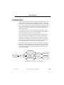
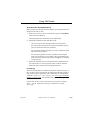
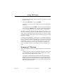
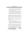
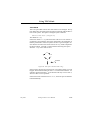
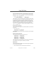
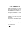
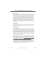
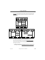
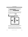
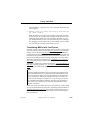
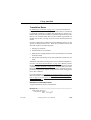
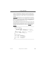
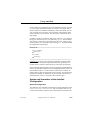
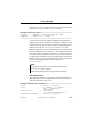
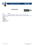
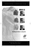
In Telelogic Tau, TTCN test suite generation is supported by TTCN
Link and Autolink. They both use an SDL specification as the basis for
test generation, but they differ in their functionality.
TTCN Link generates the TTCN declarations part automatically and
you use it for interactive building of test cases in the dynamic part.
Autolink is embedded in the SDL Validator. In addition to the SDL
specification, it uses MSCs for test purpose descriptions. With this input, Autolink generates the declarations, constraints and dynamic behavior description parts of a TTCN test suite automatically.
In comparison, the test generation features of Autolink are superior to
the ones of TTCN Link. If for some reason the test purpose description
with MSCs is not applicable, then you should use TTCN Link. In any
case, test cases built with TTCN Link can be merged with test cases
generated by Autolink.
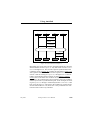
SDL Simulator
SDL Editor
SDL system
MSCs
MSC Editor
TTCN
TTCN Editor
Validator/
Autolink
TTCN Link
Figure 233: Overview of TTCN Link and Autolink
July 2003
Telelogic Tau 4.5 User’s Manual
,um-st1
1348
Introduction
TTCN Link – Generation of Declarations
TTCN Link automatically generates the TTCN declarations part based
on an SDL specification. The default dynamic behavior table is also
generated. It contains timeout and otherwise statements for each PCO,
which will ensure that any incorrect response from the implementation
under test always will give a FAIL verdict as a result from the test case.
After the default and constraints tables have been generated, you can interactively build test cases.
When you use TTCN Link, there are four (five) phases involved:
1. In the SDL Editor, you prepare an SDL specification.
2. In the Organizer, you generate a TTCN Link application.
3. In the TTCN suite, you use TTCN Link for generating the declarations part.
4. In the TTCN suite, you interactively build test cases.
5. Optionally, you may also merge the test suite with a TTCN-MP file,
possibly generated by Autolink.
For more information about TTCN Link, see “Using TTCN Link” on
page 1351.
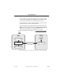
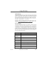
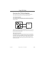
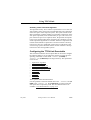
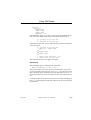
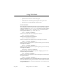
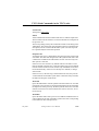
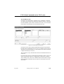
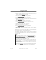
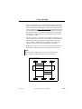
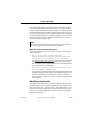
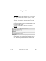
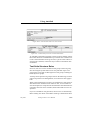
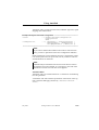
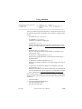
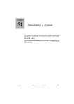
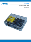
Autolink – Generation of a Test Suite
Autolink can be used for automatic generation of TTCN test suites
based on an SDL specification and a number of MSCs. The steps involved when you use Autolink are:
1. In the SDL Editor, you specify the SDL system to be used.
2. In the Organizer, you generate a Validator.
3. In the Validator, you define a number of traces through the SDL system for which you want to derive test cases. Each trace is stored as
an MSC. Alternatively, you may create the MSCs manually in the
MSC Editor or generate them with the help of the SDL Simulator.
4. In a text editor, you define an Autolink configuration. The configuration tells Autolink how to map SDL signals and signal parameters
onto TTCN constraint names, and how to group test cases and test
steps.
July 2003
Telelogic Tau 4.5 User’s Manual
,um-st1
1349
Introduction
5. In the Validator, you generate intermediate representations of the
test cases and constraints from the MSCs. This can either be done
by state space exploration or by direct translation to TTCN.
6. In the Validator, you may modify the generated constraints. Afterwards, the result is saved in a TTCN-MP file.
7. The TTCN-MP file can be opened in the TTCN suite, and to complete the test suite, the test suite overview has to be generated. On
UNIX, you have to generate it explicitly. In Windows, the overview
is generated automatically, for example before you print.
For more information about Autolink, see “Using Autolink” on page
1393.
SDL
TTCN
SDL specification
Test suite
overview
Autolink
TTCN MP File
Complete
TTCN test suite
MSC test purposes
Figure 234: Generation of a TTCN test suite with the TTCN suite and Autolink
July 2003
Telelogic Tau 4.5 User’s Manual
,um-st1
1350
Using TTCN Link
Using TTCN Link
The phases involved when you are using TTCN Link – “Preparing for
the Generation of Declarations” on page 1351, “Generating the Declarations” on page 1352 and “Creating Test Cases” on page 1358 – will
be described below. You can also read about “Showing SDL System Information” on page 1360 and “Merging TTCN Test Suites in the TTCN
Suite” on page 1360.
Preparing for the Generation of Declarations
Before it is possible to generate the declarations, you have to do two
things:
1. Adapt the SDL system to the requirements of test generation and
TTCN Link.
2. Generate a Link executable for the SDL specification.
Adapting the SDL System
The major adaptation of the SDL system that you have to do, is to modify it to properly describe the test architecture that is to be used. Basically, the requirement is that the channels from/to the environment of
the system must correspond to the points of control and observation in
the test suite. For example, the SDL system might be a specification of
a communication protocol where the lower side of the protocol in practise can only be accessed through a network. To be able to create correct
test cases, you also have to include the communication media in the
SDL specification. Note however, that the specification of the media
does not have to be a detailed specification of the functionality, only a
specification of the aspects relevant to the current testing situation.
Generating a Link Executable
Once the SDL specification describing the system to be tested and the
test architecture are finished, you can generate a Link executable. (A
Link executable is sometimes also referred to as state space generator.)
You do this in the same way as when you generate an SDL Simulator or
Validator.
July 2003
Telelogic Tau 4.5 User’s Manual
,um-st1
1351
Using TTCN Link
To generate a Link executable:
1. Select Make from the Generate menu in the Organizer.
The Make dialog will be opened.
2. Select Analyze & generate code.
3. Select Generate Makefile.
4. Select Use Standard Kernel and TTCN Link.
5. If necessary, change other options.
6. Click Full Make.
The Link executable will now be generated. It includes the information about the SDL specification that is needed for generation of the
TTCN declarations. The name of the executable will be
<sdl system name>_xxx.link, where xxx is depending on the
compiler used.
Note:
You should not change the SDL system after you have generated the
Link executable. Such changes will not affect the generated Link executable and therefore not affect the generation of declarations.
Generating the Declarations
There are two steps involved in generation of the declarations (and the
default table):
1. You select the Link Executable.
2. You start the generation.
Specifying the Link Executable
Before the actual generation of the TTCN declarations, you have to
specify the Link executable – and thereby the SDL system – to use.
There are two methods for doing this: associating the SDL and TTCN
systems in the Organizer and explicitly selecting the Link executable in
the TTCN suite. In case a Link executable has been specified both in the
Organizer and in the TTCN suite, the one selected in the TTCN suite is
the executable that will be used.
July 2003
Telelogic Tau 4.5 User’s Manual
,um-st1
1352
Using TTCN Link
Also note that the TTCN test suite that you are going to generate the
declarations in, have to be created and added to the Organizer (and the
same system file as the SDL system is included in).
Associating the SDL System with the TTCN Test Suite in the Organizer
1. In the Organizer, select the SDL system (the top node).
2. Select Associate from the Edit menu.
The Associate dialog will be opened.
3. In the dialog, select the TTCN test suite and click OK.
The association will be indicated by a new icon placed under the test
suite icon.
Selecting the Link Executable in the TTCN Suite
1. Make sure that the test suite is opened and that the Browser is active.
2. Select Select Link Executable from the SDT Link menu. On UNIX, it
is the menu in the Browser.
The Select Link Executable dialog will be opened.
3. In the dialog, select the Link executable and click OK.
Note: External synonyms
The SDL system from which the Link executable is generated may
contain external synonyms that do not have a corresponding macro
definition (see “External Synonyms” on page 2580 in chapter 57,
The Cadvanced/Cbasic SDL to C Compiler). Such an SDL system
cannot be used with TTCN Link and you will get an error message
when trying to select the Link executable.
However, if you set the environment variable SDTEXTSYNFILE to
a synonym definition file before starting Telelogic Tau, this file will
automatically be used to define the external synonyms. If
SDTEXTSYNFILE is set to “[[” all synonyms are given “null” values.
The syntax of a synonym file is described in “Reading Values at
Program Start up” on page 2581 in chapter 57, The Cadvanced/Cbasic SDL to C Compiler.
July 2003
Telelogic Tau 4.5 User’s Manual
,um-st1
1353
Using TTCN Link
Generating the TTCN Declarations
When you have specified the Link executable, you can generate the declarations in the TTCN suite:
1. Select Generate Declarations from the SDT Link menu. On UNIX, it
is the menu in the Browser.
This will generate the declarations and a default table.
2. Expand the Declarations Part and take a look:
–
One or more PCO type declarations have been generated.
–
For each channel to/from the environment in the SDL system,
one PCO declaration has been generated.
–
For each signal on these channels, one ASN.1 ASP/PDU declaration has been generated.
–
For each data type that is used as a parameter on the signals
to/from environment, a TTCN/ASN.1 data type definition has
been generated if the data type cannot be mapped to a standard
TTCN data type.
3. Expand the Dynamic Part. You should see that a default behavior
tree called Otherwise Fail is generated. This contains otherwise
statements with verdict FAIL for all generated PCOs.
PCO Mapping
There are two alternatives available for generation of the PCO types: either one PCO type is generated for each channel in the SDL system or
only one PCO type is generated. This is defined by the configuration
command define-pco-type-mapping (see “PCO Type Generation
Strategy” on page 1368). The default is that only one PCO type is generated.
If more than one PCO type is generated, they are named <ChannelName>_TypeId. If only one PCO type is generated it is called
PCO_Type.
July 2003
Telelogic Tau 4.5 User’s Manual
,um-st1
1354
Using TTCN Link
ASP/PDU Mapping
The generated ASPs/PDUs are given the same name as the corresponding SDL signal with one exception: If there are multiple PCO types and
there is one signal that can be transported on more than one channel to
the environment, this signal is divided into two ASPs, since an ASP
may only be associated with one PCO type. The ASPs are then given
names like <SDLSignalName>_<PCOName>.
By default, ASPs are generated from the SDL signals. However, you
can change it to PDUs by using the define-signal-mapping command (see “SDL Signal Mapping Strategy” on page 1369).
Data Type Mapping
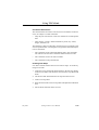
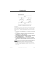
The data type mapping from SDL to TTCN/ASN.1 is defined in the following table. In most cases a table containing an ASN.1 type definition
is generated for each data type. In the table below, this is indicated by a
“<TTCN name> -> <ASN.1 definition>” clause. The <TTCN name> is
the name used to denote the type in the test suite and the <ASN.1 definition> is the ASN.1 type definition that is the contents of the generated
table. If the TTCN name is omitted, the name is given by the name of
the corresponding SDL data type.
July 2003
SDL data type
TTCN/ASN.1 data type
structure
-> SEQUENCE
array (with finite
index sort)
-> SEQUENCE OF
string
-> SEQUENCE OF
bag
-> SET OF
enumerated type
-> ENUMERATED
boolean
BOOLEAN
character
Character -> IA5String (SIZE (1))
charstring
CharString -> IA5String
integer
INTEGER
real
Real -> REAL
natural
Natural -> INTEGER (0 .. MAX)
Telelogic Tau 4.5 User’s Manual
,um-st1
1355
Using TTCN Link
SDL data type
TTCN/ASN.1 data type
syntype
-> subtype
choice
-> CHOICE
bit
Bit -> BIT STRING (SIZE (1))
bit_string
BIT_STRING -> BIT STRING
octet
Octet -> OCTET STRING (SIZE (1))
octet_string
OCTET_STRING -> OCTET STRING
ObjectIdentifier
OBJECT_IDENTIFIER -> OBJECT IDENTIFIER
IA5String
IA5String
NumericString
NumericString
PrintableString
PrintableString
VisibleString
VisibleString
Null
NULL
In addition to the data types above, data types defined in external ASN.1
modules can also be used. These data types are mapped to definitions in
the table named “ASN.1 Type Definitions by Reference” in the test
suite. For each data type in the external ASN.1 module that is used on
signals to/from the environment, one line defining the data type will be
generated in this table. Note that the Generate Declarations command
in the SDT Link menu assumes that the external ASN.1 module is setup
as a dependency of the TTCN document.
No other data types than the ones mentioned above may occur on signals to/from the environment in the system.
Note that SDL is not case sensitive whereas TTCN is case sensitive. The
spelling of the names generated by TTCN Link is given by the defining
occurrence of the corresponding SDL name. Also note that no transformation of names is performed during generation of the TTCN names.
This may in some cases lead to incorrect TTCN names if for example a
reserved word from TTCN is used in the SDL system. To fix this problem, you have to change the name in the SDL system to a legal TTCN
name.
July 2003
Telelogic Tau 4.5 User’s Manual
,um-st1
1356
Using TTCN Link
Note that the SDL character NUL is mapped to NUL. Unfortunately,
NUL is not an IA5String allowed character. So this must manually be
changed to a legal character, e.g. ““. The NUL character is especially
interesting since uninitialized SDL characters are set to NUL.
Modifying the Generated Declarations
In some cases, you may find it useful to manually modify the declarations that have been generated by TTCN Link before continuing with
the development of the test cases. There are in particular two interesting
cases:
•
ASPs vs. PDUs.
TTCN Link automatically generates ASPs for all signals visible on
the border of the SDL system unless defined otherwise by the define-signal-mapping option (see “SDL Signal Mapping Strategy”
on page 1369). If PDU definitions are more suitable for some of the
signals, this is the time to change them. The simplest way is to copy
the generated ASPs from the section ASN.1 ASP Type Definitions
and paste them as PDUs in the section ASN.1 PDU Type Definitions.
•
ASP field names.
The ASPs are generated based on the SDL signals, and since the signals in SDL have no parameter names (only types), TTCN Link automatically generates names for the ASP fields. The fields are given
the name “<type name><no>” where the <type name> is the name
of the type of this parameter (but always starting with a non-capital
letter to follow ASN.1 rules). It is however possible to change these
names in the generated definitions, and if you do it before the test
cases are developed, the new manually defined names will also be
used in the test cases.
Regeneration of Declarations
It is possible to regenerate the declarations from an SDL system to incorporate new signals, channels and/or data type into the test suite. If
you select Generate Declarations from the SDT Link menu again, only
declarations with a name different from the existing test suite declarations will be inserted into the test suite.
July 2003
Telelogic Tau 4.5 User’s Manual
,um-st1
1357
Using TTCN Link
Creating Test Cases
To create test cases with TTCN Link, you use the Table Editor in the
TTCN suite. When TTCN Link is used, the test cases are synchronized,
that is, verified against the SDL specification.
In synchronized mode, the test case is guaranteed to be consistent with
the specification. Each action you perform during the development of
the test case will be incrementally verified by the state space exploration
part of TTCN Link. When a table is in synchronized mode, the SDT
Link menu of the UNIX Table Editor will contain new menu choices for
editing of the test case. In Windows, you can find the corresponding
commands in the Link dialog:
•
Send will add a send statement to the test case. This is a manual step
where you define the constraint to be associated with the send statement.
•
Receive automatically generates all valid responses from the system
under test. This implies that you do not need to check with the specification which possible signals the system can send in the state it is
driven to by the proceeding lines in the test case.
•
Start timer and Cancel timer are also manual commands where
TTCN timers are started and cancelled. However, note that the timeout event corresponding to the timer will be automatically generated as a result of a Receive command.
•
Attach test step will attach a previously defined test step, while still
keeping the editor in synchronized mode.
If you modify the contents of the test case by using other menu choices,
the editor will leave the synchronized mode.
The verdict for the generated test case lines, will always be either PASS
or INCONCLUSIVE since the generated receive lines will always correspond to valid behaviors of the implementation under test.
A default test step, which consists of an otherwise fail for each PCO,
will ensure that an incorrect response from the implementation under
test always will give a FAIL verdict as a result from the test case.
July 2003
Telelogic Tau 4.5 User’s Manual
,um-st1
1358
Using TTCN Link
Constraint Restrictions
The constraints that are used in send and receive statements in the test
cases, are subject to certain restrictions:
•
They may not use test suite or test case variables or test suite parameters.
•
They must be “exactly” defined without any omits, any values,
ranges, wildcards, etc.
The following is however allowed in send and receive constraints a test
case is resynchronized, even though it is not generated automatically for
receive constraints:
•
The constraints can be structured/chained, that is, the constraints
can reference and use other constraints defined in the test suite.
•
The constraints can use test suite constants.
•
The constraints can be parametrized.
Creating Test Steps
It is often useful to structure the test case into test steps. To do this by
using TTCN Link:
1. Create the TTCN statements that should be in the test step directly
in the test case table. This should of course be done in synchronized
mode.
2. Cut the lines that should form the test step from the test case.
3. Create a test step table.
4. Paste the lines into the new test step table and adjust the indentation
level.
5. Add an attach statement to the test case.
July 2003
Telelogic Tau 4.5 User’s Manual
,um-st1
1359
Using TTCN Link
Showing SDL System Information
When you use TTCN Link for creating a test case, it is possible to access the SDL specification from the Table Editor.
To do this you first select a line in the test case. Then you have three
alternatives:
•
Select Show SDL from the SDT Link menu.
The SDL Editor will be opened and display the executed SDL symbols that correspond to the selected test case line.
•
Select Show Coverage from the SDT Link menu.
This will display the Coverage Viewer and coverage information
for the current test case.
•
Select Show MSC from the SDT Link menu.
The MSC Editor will be opened with a generated MSC diagram
showing the execution path from the start of the SDL system to the
state corresponding to the selected line in the test case. This may be
particularly useful if you need to find out how unexpected receive
statements are possible.
Merging TTCN Test Suites in the TTCN Suite
By using TTCN Link, you can only generate the declarations and create
the dynamic tables. Either you could add the constraints and dynamic
tables manually or merge the TTCN Link generated test suite with one
generated by Autolink. A test suite generated by Autolink is in TTCNMP format and contains constraints, declarations and dynamic tables.
To merge the test suites:
1. Make sure that the test suite that you want to merge the MP file into
– that is, the destination document – is opened and active.
2. In Windows, select Autolink Merge from the File menu.
On UNIX, select Autolink Merge from the SDT Link menu in the
Browser.
A dialog will be opened.
July 2003
Telelogic Tau 4.5 User’s Manual
,um-st1
1360
Using TTCN Link
3. Find and select the MP file that you want to merge with the currently
opened test suite.
4. Click OK (in Windows) or Merge (on UNIX).
The MP file you selected will be merged into the currently opened
test suite.
To complete the test suite on UNIX, you also have to generate the test
suite overview. In Windows, the overview is generated automatically, for example before you print, and after that it is kept updated.
The merge will only work if the two test suites do not conflict. A conflict occurs if any TTCN object in the MP file has the same name as any
TTCN object in the destination document. However, if such a conflict
is detected, the merge will continue but the conflicting object in the MP
file will be skipped.
Constraints will be merged in a special way. For example, the MP file
may contain a TTCN ASP constraint called constraint1 that refers to the
type type1 which is of the incompatible type TTCN PDU TypeDef. Because of this, a copy of constraint1 will be inserted as a TTCN PDU
constraint instead. However, this “type conversion” is limited. An
ASN.1 constraint will not be converted to a TTCN constraint or vice
versa.
Summary of TTCN Link
TTCN Link supports test case development and there are two major objectives:
July 2003
•
To help solving the consistency problem that arises as soon as there
are two different descriptions of the same system, in this case the
SDL specification and the TTCN test suite.
•
To supply an environment that, based on the SDL specification,
supports test suite development during the TTCN design. Both by
directly using the SDL specification, for example to generate the
declarations, and by providing access to the SDL specification directly from the TTCN suite.
Telelogic Tau 4.5 User’s Manual
,um-st1
1361
Using TTCN Link
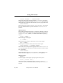
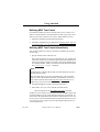
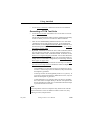
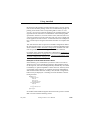
Overview of the TTCN Link Algorithm
This section will give a brief introduction to the algorithm used by
TTCN Link to synchronize a test case with an SDL system.
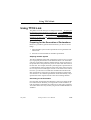
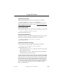
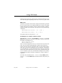
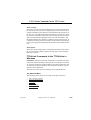
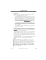
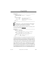
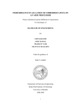
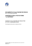
The Composed System
The system that TTCN Link analyzes is the composed system that consists of both the SDL specification and the TTCN test case that is interactively created.
SDL specification
TTCN
test case
Figure 235: A composed SDL/TTCN system
The connection between the SDL system and the TTCN test case is created by connection of the channels to/from environment in the SDL system to the PCOs in the test suite.
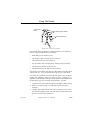
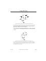
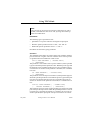
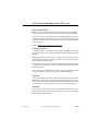
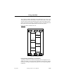
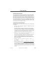
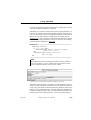
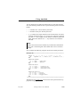
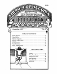
State Space Exploration
The technique used by TTCN Link is based on state space exploration
(sometimes referred to as reachability analysis) of the system composed
of the SDL system together with the test case that is being created. The
state space of this system can be viewed as a graph, where the nodes
represent system states and the edges represent actions that can be performed by the system.
July 2003
Telelogic Tau 4.5 User’s Manual
,um-st1
1362
Using TTCN Link
start system
state
SDL/TTCN system states
SDL/TTCN actions
Figure 236: A state space fragment
Each system state represents the combined system in one moment in
time. It contains information of for example:
•
What SDL process instances exist
•
The variable values of all the process instances
•
The control flow state of the instances
•
Any procedure calls, including local variables in the procedures
•
The current line number of the test case
•
Any started timers, both SDL and TTCN timers
The actions represented by the edges are either SDL actions like input,
output, tasks, etc., or TTCN actions like send, receive or start timer.
Essentially, the algorithm to generate the state space of the combined
system is the following, where two global variables – StateSpace (a
graph that will contain the state space of the system) and TreatList (a list
of states that is yet to be treated by the algorithm) – are used:
1. Create the start system state and add it to StateSpace and TreatList.
2. Remove one state (in step 3–4 called the current state) from
TreatList.
3. Compute all possible actions that can be performed in the current
state and the resulting system state that will be reached when the respective action has been performed.
July 2003
Telelogic Tau 4.5 User’s Manual
,um-st1
1363
Using TTCN Link
4. For each action/resulting state:
–
If the resulting state was not already in StateSpace, add it to
TreatList.
–
Add the action/resulting state to StateSpace.
5. If TreatList is empty: Terminate algorithm, the state space of the
system is now represented by the graph in StateSpace.
If TreatList is not empty: Go to step 2.
Incremental State Space Exploration
Since you interactively create the test case that describes the TTCN part
of the combined SDL/TTCN system, it is not possible for TTCN Link
to compute the entire state space at once. Instead, the state space exploration is performed in an incremental fashion in the following way:
1. You compute the state space that can be reached without any action
by the test case.
2. When you TTCN Link to add a TTCN statement to a leaf in the test
tree, you add the corresponding TTCN action(s)/resulting system
state(s) to the state space.
3. Generate the state space that can be reached from the newly created
system state(s) without any further action by the test case.
4. Go to step 2.
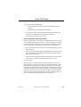
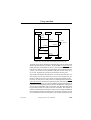
The consequence of this algorithm is that the state space of the combined SDL/TTCN system is explored in an incremental fashion, where
each increment corresponds to a command you have given. Also the
structure of the state space is influenced by the incremental way that it
is generated. The state space can be visualized as a tree structure, where
each node represents one line in the test case and a subpart of the state
space, to be more precise, the subpart of the state space where the test
case has executed this particular line but not the next one.
July 2003
Telelogic Tau 4.5 User’s Manual
,um-st1
1364
Using TTCN Link
Nodes corresponding
to lines in the
test case
Subspaces in the
state space for the
SDL/TTCN system
Figure 237: A structured state space
Since each line in the test case is created by a command from you, each
node with its associated part of the state space can also be viewed as the
state space increment that was created by a specific command.
Random Walk Exploration
The default state space exploration algorithm used by TTCN Link is the
algorithm described in the previous sections. This is usually referred to
as exhaustive exploration since it exhaustively explores the state space
until all reachable states has been generated. The benefit of this algorithm is that when the exploration is finished, you can be sure that all
possible combinations and alternatives are explored, that is, if TTCN
Link generates two alternatives in a receive statement, the algorithm
guarantees that there are no more valid alternatives. However, the drawback is that the algorithm requires all states in the state space to be kept
in primary memory. For large SDL systems this may not always be possible with the computers available. The response time may also be unacceptable for interactive work with large systems.
To be able to use TTCN Link even in these cases, a second exploration
algorithm is also provided. This is the random walk algorithm that, instead of exploring the entire state space, explores random paths in the
state space using the algorithm described below. The input to the algorithm is a set of start states called StartList and a maximum depth of the
exploration (MaxDepth) and the number of repetitions (Rep):
July 2003
Telelogic Tau 4.5 User’s Manual
,um-st1
1365
Using TTCN Link
1. Select one state (in step 2–4 called the current state) from StartList.
2. Compute all possible actions that can be performed in the current
state and the resulting system states that will be reached when the
respective action has been performed.
3. If no actions could be performed from the current state or if the
depth of the current random walk is MaxDepth, the current random
walk is pruned. If the number of random walks performed so far is
less than Rep, go to step 1, otherwise terminate the algorithm.
4. If actions could be performed and the depth is less than MaxDepth,
select one of the generated states as a new current state and go to
step 2.
The benefit with the random walk algorithm is that not more than a few
system states (the current state and its successors) need to be kept in the
memory at the time. The drawback is that there is no guarantee that the
entire state space is explored, so, for example, even if TTCN Link generates only one receive alternative, it is possible that there are more alternatives.
To accomplish the best, both from exhaustive exploration and random
walk, a two-step approach can be used when you use TTCN Link for
large SDL systems:
1. Develop the test cases interactively by using the random walk algorithm with a small number of repetitions (1–3).
2. Verify that no more receive alternatives were possible by resynchronizing the test cases and using the exhaustive exploration algorithm. Or, if this is not possible due to lack of memory, use random
walk with a high number of repetitions (at least 10, preferably 50–
100).
This strategy gives both good performance when you interactively create the test cases and a good verification of the correctness of the test
case during the automatic resynchronize. The execution time of the random walk algorithm is proportional to the number of repetitions.
You select which algorithm to use in the .linkinit file (on UNIX) or
the linkinit.com file (in Windows) by using the
define-algorithm command as described in section “Configuring
the TTCN Link Executable” on page 1367.
July 2003
Telelogic Tau 4.5 User’s Manual
,um-st1
1366
Using TTCN Link
Summary of the TTCN Link Algorithm
The algorithm used by TTCN Link to resynchronize a TTCN test case
with an SDL system, is based on an incremental state space exploration
of the state space of the composed system. The system consists of the
SDL specification, together with the test case under construction. In the
state space exploration, each command that you give will cause a new
part of the state space to be explored, that is, the part that corresponds
to the TTCN statement line that is inserted by the command. Two different exploration algorithms are available: exhaustive exploration and
random walk. Exhaustive exploration is used for interactive development of test cases for a small SDL system and for verification of test
cases for large systems. Random walk is used for interactive development of test cases for large SDL systems.
Configuring the TTCN Link Executable
This section describes the various options that can be used to configure
the Link executable. You can change the options by giving the corresponding commands in a file called .linkinit (on UNIX) or
linkinit.com (in Windows) in the target directory. The options that
can be set are:
•
•
•
•
•
•
•
•
•
•
Exploration Algorithm
Random Walk Depth
Random Walk Repetitions
PCO Type Generation Strategy
SDL Signal Mapping Strategy
Stable State
Timer Mode
Transition
Scheduling
MSC Trace
These options will be described below.
It is also possible to add user-defined rules to the .linkinit file (on
UNIX) or the linkinit.com file (in Windows) in order to prune the
state space that is explored by Link. The user-defined rules are described in “User-Defined Rules” on page 1376.
July 2003
Telelogic Tau 4.5 User’s Manual
,um-st1
1367
Using TTCN Link
Exploration Algorithm
What exploration algorithm is used, is defined by the command
define-algorithm [exhaustive|randomwalk]
and has the default value exhaustive. The differences between the
different algorithms are described in section “Overview of the TTCN
Link Algorithm” on page 1362.
Random Walk Depth
The maximum depth of each random walk is defined by the command
define-randomwalk-depth <integer>
and has the default value 500.
Random Walk Repetitions
The number of times a random walk is performed when a state space is
explored by using this algorithm is defined by the command
define-randomwalk-repetitions <integer>
with a default value of 3.
PCO Type Generation Strategy
The PCO Type generation strategy is defined by the command
define-pco-type-mapping [system|channel]
and has default value system.
•
If the parameter given is system then only one PCO type is generated for the entire system.
•
If the parameter is channel then one PCO type is generated for
each channel to/from the environment.
The choice also has an impact on the ASPs that are generated from SDL
signals. Usually the name of the ASP is the same as the name of the SDL
signal. However, if one PCO type is generated for each channel to/from
the environment and one SDL signal can appear on more than one of
these channels, then one ASP is generated for each channel it appears
on. This is needed since an ASP can only be associated with one PCO
type. The names of the signals are in this case defined as <signal
name>_<channel name>.
July 2003
Telelogic Tau 4.5 User’s Manual
,um-st1
1368
Using TTCN Link
SDL Signal Mapping Strategy
The SDL signals that appear on channels to/from the environment in the
SDL system are either mapped to ASN.1 PDU or ASN.1 ASP definitions in the test suite. The mapping is defined by the command
define-signal-mapping [asp|pdu]
and has default value asp.
Stable State
The stable state option is defined by the command
define-stable [on|off]
and has the default value on.
It works like this:
Consider the situation when an empty test case has been resynchronized. The Link executable will now have computed the state space that
can be reached without any input from or output to the tester. Usually,
the state space looks something like this:
0
1
3
2
4
5
Figure 238: Original state space
where 0 is the start state, 1–4 are intermediate states and 5 is a stable
state where all internal queues in the SDL system are empty and nothing
more can happen without any input from the tester.
Let us now give a send command. This implies that new states are created as send transitions are added to the state space.
If the stable state assumption is off then we add one send transition to each state in the original state space, the new state space looks
something like this:
July 2003
Telelogic Tau 4.5 User’s Manual
,um-st1
1369
Using TTCN Link
0
0a
2
1
1a
3
2a
4
4a
3a
5
5a
Figure 239: The new state space with stable state assumption “off”
where all states called something with ‘a’ are new. Now the states space
that contains states that can be reached from the ‘a’ states without any
input from or output to the tester is explored.
On the other hand, if the stable state assumption is on then we only add
a send transition to the stable state, giving a new state space looking like:
0
1
3
2
4
5
5a
Figure 240: The new state space with stable state assumption “on”
Now, only the states that can be reached from “5a” without any input
from or output to the tester are explored. This state space is of course a
lot smaller that the one above.
July 2003
Telelogic Tau 4.5 User’s Manual
,um-st1
1370
Using TTCN Link
Timer Mode
This is an option that in most cases will not have to be changed. The option defines how to interpret timeout actions compared with all other actions in the system. The option is changed by the command:
define-timer-mode [long|short]
The default is long.
If the timer mode is long, timeout actions will never occur if there is
an internal event possible in the system. Essentially, the assumption is
that the performance of the test system and IUT is good enough to ensure that the execution time for the actions are very small compared to
the timeout times. Consider a system with the following state space
when the long timer mode is used:
0
1
2
3
timeout
4
Figure 241: State space with timer mode “long”
In this system, the timeout event does not occur until no other event can
happen. The transition leading to states 1–3 are all usual transitions – for
example. inputs and outputs – so the timeout will only occur in state 3,
where no other event is possible.
If the timer mode would have been short, the state space would have
looked differently:
July 2003
Telelogic Tau 4.5 User’s Manual
,um-st1
1371
Using TTCN Link
0
0b
1
1b
2
2b
3
4
Figure 242: State space with timer mode “short”
The reason is that the timeout event now is possible in all the states 0–3.
Transition
The transition option defines what is considered to be an atomic transition in the state space and is defined by the command:
define-transition [‘sdl’|’symbol’]
The default value is symbol.
If the transition option is set to sdl, then SDL process graph transitions
are considered atomic. This means that there will be no states in the state
space where SDL processes are in the middle of a process graph transition. In all system states in the state space, the processes will always be
in a process graph state.
If the transition option is set to symbol, the SDL process graph transitions are not considered to be atomic. In theory, this would imply that
the processes could be interrupted anywhere during the execution of a
transition. However, it turns out that for test generation purposes it is
enough if the process graph transitions are divided at the points where
one process communicates with another process, for example after an
output or a create. A sequence of tasks or decisions is still viewed as
atomic.
The consequence of this is that there will be more transitions in the state
space if the transition option is symbol than if it is sdl. Consider a
simple system with only one process. Let this process have a transition
like:
July 2003
Telelogic Tau 4.5 User’s Manual
,um-st1
1372
Using TTCN Link
state xx;
input st1;
output sig2;
output sig3;
output sig4
nextstate st2;
If the transition option is sdl, there will only be one transition in the
state space that corresponds to the process graph transition above:
X : process is in state st1
|
Y : process is in state st2
If the transition option is symbol, there will be a sequence of transitions
in the state space:
X : process is in state st1
| input st1; output sig2;
X1
| output sig2;
X2
| output sig3;
X3
| output sig4; nextstate st2;
Y : process is in state st2
This will of course give a lot bigger state space.
Scheduling
The scheduling option is defined by the command
define-scheduling [‘first’|’all’]
This option controls how many processes are allowed to execute in a
given system state. If the option is set to first, only one process (the
first in the ready queue) is allowed to execute. If the option is set to all,
all processes that can execute are allowed to do it. The default value is
all.
Consider an SDL system with two static processes. If the scheduling option is all, the initial part of the state space for this system will probably look like:
July 2003
Telelogic Tau 4.5 User’s Manual
,um-st1
1373
Using TTCN Link
0
1
2
3
Figure 243: State space with scheduling as “all”
where
•
0 is the initial state (both processes are in the start symbol).
•
1 is the state where the first process has executed its start transition
while the second process is still in its start symbol.
•
2 is the state where the second process has executed its start transition while the first process is still in its start symbol.
•
3 is the state where both processes have executed their start transitions.
On the other hand, if the scheduling option is first, it will look like:
0
1
2
Figure 244: State space with scheduling as “first”
where
July 2003
•
0 is the initial state (both processes are in the start symbol).
•
1 is the state where the first process has executed its start transition
while the second process is still in its start symbol.
•
2 is the state where both processes have executed their start transitions.
Telelogic Tau 4.5 User’s Manual
,um-st1
1374
Using TTCN Link
If there are lots of processes, there will be a significant difference in the
size of the state space depending on how the scheduling option is set!
MSC Trace
The MSC trace options control what is displayed in the MSCs generated
by TTCN Link. There are two different MSC trace options controlling
if states and actions in the SDL system are showed as MSC condition
symbols and MSC action symbols. The options are set by the following
commands:
define-MSC-trace-actions [ ‘on’ | ‘off’ ]
define-MSC-trace-states [ ‘on’ | ‘off’ ]
The default value for both options is ‘off’.
An Example of a .linkinit / linkinit.com File
This following .linkinit file (on UNIX) or linkinit.com file (in
Windows) will change the exploration algorithm to random walk and set
the number of repetitions to 2:
define-algorithm random
define-random-rep 2
This is a useful configuration when you work interactively with TTCN
Link, since the random walk algorithm is quicker and requires less
memory than the exhaustive algorithm. But, since the random walk in
some cases can miss some alternative receive statement, a useful strategy is the following: Use the configuration above when you work interactively with TTCN Link. However, when you have finished with a test
case or a number of test cases, check that the assumptions are valid by
resynchronizing with the exhaustive algorithm or a larger number of
repetitions.
Note that in the commands in the .linkinit file (on UNIX) and the
linkinit.com file (in Windows) can be abbreviated as long as they are
unique.
July 2003
Telelogic Tau 4.5 User’s Manual
,um-st1
1375
Using TTCN Link
User-Defined Rules
User-defined rules can be used during state space exploration to prune
the search performed by the TTCN Link. Whenever a system state is
found that matches the defined rule, the search is pruned at this particular state. This can be useful in order to remove specific exceptional behavior from the test cases that are designed and instead handle these in
a special default test step.
Consider an SDL specification that contains a clock process that has
a timer intervaltimeout. Every time the intervaltimeout expires, a signal DisplayTime is sent to the environment of the SDL system. Since this can happen at any time during the execution, there will
be an alternative at all receive statements corresponding to the reception
of this signal. To avoid this, it is better to add a receive statement in the
default dynamic behaviour that skips this signal.
To achieve this with TTCN Link, you have to do two things:
•
Define a rule that prunes the state space at appropriate places.
•
Modify the default dynamic behaviour that is generated by TTCN
Link.
A rule that prunes the state space whenever the intervaltimer expires is the following:
def-rule sitype(signal(clock:1))=intervaltimeout;
The statements that need to be added to the default behaviour are:
PCO?DisplayTime
RETURN
DisplayTime_Match_All
These lines will cause the tester to ignore DisplayTime signals sent
from the system.
A rule essentially gives the possibility to define predicates which describe properties of one particular system state. As soon as this predicate matches a system state, TTCN Link will prune the search. A rule
consists of a predicate (as described below) followed by a semicolon
(‘;’). In a rule, all identifiers and reserved words can be abbreviated as
long as they are unique.
July 2003
Telelogic Tau 4.5 User’s Manual
,um-st1
1376
Using TTCN Link
Note:
Only one rule can be used at any moment. If more than one rule is
needed, reformulate the rules as one rule, by using the boolean operators described below.
Predicates
The following types of predicates exist:
•
Quantifiers over process instances and signals in input ports
•
Boolean operator predicates such as “and”, “not” and “or”
•
Relational operator predicates such as “=” and “>”
Parenthesis are allowed to group predicates.
Quantifiers
The quantifiers listed below are used to define rule variables denoting
process instances or signals. The rule variables can be used in process
or signal functions described later in this section.
exists <RULE VARIABLE> [: <PROCESS TYPE>]
[ | <PREDICATE>]
This predicate is true if there exists a process instance (of the specified
type) for which the specified predicate is true. Both the process type and
the predicate can be excluded. If the process type is excluded, all process instances are checked. If the predicate is excluded, it is considered
to be true.
all <RULE VARIABLE> [ : <PROCESS TYPE>]
[ | <PREDICATE>]
This predicate is true for all process instances (of the specified type) for
which the specified predicate is true. Both the process type and the predicate can be excluded. If the process type is excluded, all process instances are checked. If the predicate is excluded, it is considered to be
true.
siexists <RULE VARIABLE> [ : <SIGNAL TYPE>]
[ - <PROCESS INSTANCE>] [ | <PREDICATE>]
This predicate is true if a signal (of the specified type) exists in the input
port of the specified process for which the specified predicate is true. If
no signal type is specified, all signals are considered. If no process instance is specified, the input ports of all process instances are consid-
July 2003
Telelogic Tau 4.5 User’s Manual
,um-st1
1377
Using TTCN Link
ered. If no predicate is specified, it is considered to be true. The specified process can be either a rule variable that has previously been defined in an exists or all predicate, or a process instance identifier
(<PROCESS TYPE>:<INSTANCE NO>).
siall <RULE VARIABLE> [ : <SIGNAL TYPE>]
[ - <PROCESS INSTANCE>] [ | <PREDICATE>]
This predicate is true for all signals (of the specified type) in the input
port of the specified process for which the specified predicate is true. If
no signal type is specified, all signals are considered. If no process is
specified, the input ports of all process instances are considered. If no
predicate is specified, it is considered to be true. The specified process
can be either a rule variable that has previously been defined in an
exists or all predicate, or a process instance identifier (<PROCESS
TYPE>:<INSTANCE NO>).
Boolean Operator Predicates
The following boolean operators are included (with the conventional interpretation):
not <PREDICATE>
<PREDICATE> and <PREDICATE>
<PREDICATE> or <PREDICATE>
The operators are listed in priority order, but the priority can be changed
by parenthesis.
Relational Operator Predicates
The following relational operator predicates exist:
<EXPRESSION>
<EXPRESSION>
<EXPRESSION>
<EXPRESSION>
<EXPRESSION>
<EXPRESSION>
= <EXPRESSION>
!= <EXPRESSION>
< <EXPRESSION>
> <EXPRESSION>
<= <EXPRESSION>
>= <EXPRESSION>
The interpretation of these predicates is conventional. The operators are
only applicable to data types for which they are defined.
Expressions
The expressions that are possible to use in relational operator predicates
are of the following categories:
•
July 2003
Process functions: Extract values from process instances
Telelogic Tau 4.5 User’s Manual
,um-st1
1378
Using TTCN Link
•
Signal functions: Extract values from signals
•
Global functions: Examine global aspects of the system state
•
SDL literals: Conventional SDL constant values
Process Functions
Most of the process functions must have a process instance as a parameter. This process instance can be either a rule variable that has previously been defined in an exists or all predicate, a process instance
identifier (<PROCESS TYPE>:<INSTANCE NO>) or a function that returns a process instance, e.g. sender or from.
state( <PROCESS INSTANCE> )
Returns the current SDL state of the process instance.
type( <PROCESS INSTANCE> )
Returns the type of the process instance.
iplen( <PROCESS INSTANCE> )
Returns the length of the input port queue of the process instance.
sender( <PROCESS INSTANCE> )
Returns the value of the imperative operator sender (a process instance)
for the process instance.
parent( <PROCESS INSTANCE> )
Returns the value of the imperative operator parent (a process instance)
for the process instance.
offspring( <PROCESS INSTANCE> )
Returns the value of the imperative operator offspring (a process instance) for the process instance.
self( <PROCESS INSTANCE> )
Returns the value of the imperative operator self (a process instance) for
the process instance.
signal( <PROCESS INSTANCE> )
Returns the signal that is to be consumed if the process instance is in an
SDL state. Otherwise, if the process instance is in the middle of an SDL
process graph transition, it returns the signal that was consumed in the
last input statement.
July 2003
Telelogic Tau 4.5 User’s Manual
,um-st1
1379
Using TTCN Link
<PROCESS INSTANCE> -> <VARIABLE NAME>
Returns the value of the specified variable. If <PROCESS INSTANCE>
is a previously defined rule variable, the exists or all predicate that
defined the rule variable must also include a process type specification.
<RULE VARIABLE>
Returns the process instance value of <RULE VARIABLE>, which must
be a rule variable bound to a process instance in an exists or all
predicate.
Signal Functions
Most of the signal functions must have a signal as a parameter. This signal can be either a rule variable that has previously been defined in an
siexists or siall predicate, or a function that returns a signal, e.g.
signal.
sitype( <SIGNAL> )
Returns the type of the signal.
to( <SIGNAL> )
Returns the process instance value of the receiver of the signal.
from( <SIGNAL> )
Gives the process instance value of the sender of the signal.
<RULE VARIABLE> -> <PARAMETER NUMBER>
Returns the value of the specified signal parameter. The siexists or
siall predicate that defined the rule variable must also include a signal
type specification.
<RULE VARIABLE>
Returns the signal value of <RULE VARIABLE>, which must be a rule
variable bound to a signal in a siexists or siall predicate.
Global Functions
maxlen( )
Gives the length of the longest input port queue in the system.
instno( [<PROCESS TYPE>] )
Returns the number of instances of type <PROCESS TYPE>. If
<PROCESS TYPE> is excluded the total number of process instances is
returned.
July 2003
Telelogic Tau 4.5 User’s Manual
,um-st1
1380
Using TTCN Link
depth( )
Gives the depth of the current system state in the behavior tree/state
space.
SDL Literals
<STATE ID>
The name of an SDL state.
<PROCESS TYPE>
The name of a process type.
<PROCESS INSTANCE>
A process instance identifier of the format
<PROCESS TYPE>:<INSTANCE NO>, e.g. Initiator:1.
<SIGNAL TYPE>
The name of a signal type.
null
SDL null process instance value
env
Returns the value of the process instance in the environment that is the
sender of all signals sent from the environment of the SDL system.
<INTEGER LITERAL>
true
false
<REAL LITERAL>
<CHARACTER LITERAL>
<CHARSTRING LITERAL>
SDL Restrictions
The restrictions imposed on the SDL specification by TTCN Link are
basically of four different kinds:
•
•
•
•
July 2003
General SDL restrictions
State space exploration restrictions
Data type mapping restrictions
TTCN name restrictions
Telelogic Tau 4.5 User’s Manual
,um-st1
1381
Using TTCN Link
General SDL Restrictions
TTCN Link is based on the SDL to C compiler and has thus the same
restrictions as the Simulator and Validator which are also based on the
SDL to C compiler. The major restrictions are:
•
No context parameters
•
No channel substructures
•
No signal refinements
•
No axioms, literal mappings, inheritance or name class literals in
abstract data types
For more information about the general SDL restrictions see “SDL Restrictions” on page 33 in chapter 2, Release Notes, in the Release Guide.
State Space Exploration Restrictions
TTCN Link is based on state space exploration of the combined state
space of the SDL system and the TTCN test case. Since there is only a
finite amount of memory available in computers, this means that there
will be restrictions on the size of the state space that can be handled. It
is not possible to give a numeric value on this restriction since it depends both on the SDL system and on the computer, but TTCN Link has
been successfully used on SDL systems with more than 10 processes on
a SPARCstation 10 computer. Also see “Overview of the TTCN Link
Algorithm” on page 1362.
Data Type Mapping Restrictions
Only the data types described in section “Generating the Declarations”
on page 1352 are allowed on the channels to/from the system.
TTCN Name Restrictions
The mapping of concepts from SDL to TTCN generates a lot of names
in TTCN. For example, the signals in SDL will become ASPs/PDUs in
TTCN and SDL data types will become TTCN data types. The names
of the generated entities are taken directly from the names on the corresponding SDL entity. This will lead to problems if, for example, the
names are reserved words in TTCN. In this case, the names in the SDL
system have to be changed.
July 2003
Telelogic Tau 4.5 User’s Manual
,um-st1
1382
TTCN Link Commands in the TTCN suite
TTCN Link Commands in the TTCN suite
TTCN Link Commands in the TTCN Suite on
UNIX
This section describes the extra menu choices that are available in the
TTCN suite when TTCN Link is used on UNIX.
Browser Commands in the SDT Link Menu
The following menu choices are available in the Browser SDT Link
menu:
•
•
Select Link Executable
Generate Declarations
Select Link Executable
Makes a connection between a test suite and the corresponding SDL
system. In the file dialog that opens, a Link executable should be selected. If the file is not a legal Link executable, the selection will fail.
When a Link executable is selected, a place holder for it is stored in the
test suite. It is possible to change the Link executable if, and only if,
there is no test case which uses the current SDL system (i.e. there is no
synchronized test case).
It is also possible to select a Link executable by associating the SDL
system with the TTCN system in the Organizer. However, a Link executable selected in the TTCN suite will override an executable selected
in the Organizer.
See also “External synonyms” on page 1353.
Generate Declarations
Generates TTCN versions of the relevant type declarations in the SDL
system. The menu choice is only available if a Link executable has been
selected.
The generated objects use the ASN.1 syntax. They are automatically analyzed after they have been generated. This is necessary for later operations and usage of these types. If there is no other declarations (types)
in the test suite (e.g. the test suite is empty), the analysis will not fail.
On the contrary if other declarations (types) already exist, the analysis
July 2003
Telelogic Tau 4.5 User’s Manual
,um-st1
1383
TTCN Link Commands in the TTCN suite
may fail due to name conflicts and incorrect references. The error messages of this analyzing will not be displayed. To check if the generated
declarations are analyzed, use the Selector and the Show Error Message
command on the incorrect tables.
At the same time that the declarations are generated, a Default table will
be generated. It consists of an otherwise statement for each PCO and a
timeout statement.
No timer will be generated from the SDL system. If the design of the
test suite requires any timers they must be defined manually.
More details about the generated tables etc. can be found in “Generating
the Declarations” on page 1352.
Table Editor Commands in the SDT Link Menu
To generate a test case (the behaviour description of a test case), the test
case table must be in synchronized mode. In synchronized mode, the
test case is synchronized (has an established connection) with the selected Link executable.
Once in synchronized mode, the test case editor will stay in this mode
as long as only commands from the SDT Link menu are used. As soon
as any field in the table (besides the comment fields) is edited, the synchronized mode will be terminated. It is however possible to analyze the
test case without leaving the synchronized mode.
The following commands are available from a Table Editor for test cases or test steps. They are applied on a behaviour line (they insert a new
behaviour line below/after the behaviour line with the input focus)
hence it is required that the test case or the test step either is empty or
has the input focus on a leaf row.
When each of these commands is performed the input focus is moved
to the new generated behaviour line.
•
•
•
•
•
•
•
•
July 2003
Send
Receive
Start Timer
Cancel Timer
Attach
Resynchronize
Show SDL
Show MSC
Telelogic Tau 4.5 User’s Manual
,um-st1
1384
TTCN Link Commands in the TTCN suite
•
•
Show Coverage
Show Options
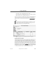
Send
Adds a send statement below/after the behaviour line with the input focus. The new behaviour line will have an increased indent level compared with the previous one.
Figure 245: Send dialog
The send statement with the selected PCO, ASP/PDU and constraint
will be verified by the selected SDL system. If the verification does not
fail, a send statement is generated and inserted below/after the row with
the input focus. For a more detailed description of this dialog, see “Add
Send Statement” on page 1172 in chapter 26, The TTCN Table Editor
(on UNIX).
Receive
Adds appropriated receive and/or timeout statement(s) below/after the
behaviour line with the input focus. The new row(s) will have the same
July 2003
Telelogic Tau 4.5 User’s Manual
,um-st1
1385
TTCN Link Commands in the TTCN suite
indent level. This indent level will be increased compared with the previous one.
For each retrieved receive statement from the SDL system, a new Constraint is generated if there is no appropriate Constraint (a Constraint
with a similar value). The new Constraint will be named with a unique
name and will be analyzed. This new name is used in the Constraints
Ref column.
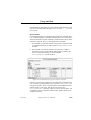
Start Timer
Adds a start timer statement below/after the behaviour line with the input focus. The new behaviour line will have an increased indent level
compared to the previous one.
Figure 246: Start Timer dialog
The start timer statement with the selected timer will be verified with
the selected SDL system. If the verification does not fail, a start timer
statement is generated and inserted below/after the behaviour line with
the input focus. For a more detailed description of this dialog see “Add
Send Statement” on page 1172 in chapter 26, The TTCN Table Editor
(on UNIX).
July 2003
Telelogic Tau 4.5 User’s Manual
,um-st1
1386
TTCN Link Commands in the TTCN suite
Cancel Timer
Analogous to Start Timer.
Attach
Adds an attachment statement below/after the row with the input focus.
The new behaviour line will have an increased indent level compared to
the previous one.
The test step dialog used by this command is similar to the dialog in the
Table Editor. The selected test step (the behaviour lines in the behaviour
description) will be verified with the SDL system. The test step must
have passed analysis before this operation.
Resynchronize
Verifies the test case in a Table Editor using the previously chosen Link
executable. The table will change mode to the synchronized mode. This
command is available from Table Editors for test cases and only if an
SDL system is selected.
If the test case does not have any default reference and there is more
than one default in the test suite, a selection dialog pops up and a default
must be selected. If the test suite contains only one default, it will be selected automatically. If the test case already has a default, no change
will be made.
If the test case (or the test step) contains behaviour lines, they will be
verified with the current SDL system. If the verification of any line fails,
the table will keep the normal mode.
Show SDL
Opens the SDL Editor with the symbols selected which were executed
in the SDL system and are associated with the behaviour line which has
the input focus. More precisely, the SDL symbols which were executed
after the current test case line but before the next test case line, are selected exactly.
Show MSC
Opens the MSC Editor with a process level MSC that illustrates the execution path from the start of the SDL system to the state corresponding
to the behaviour line with input focus.
July 2003
Telelogic Tau 4.5 User’s Manual
,um-st1
1387
TTCN Link Commands in the TTCN suite
Show Coverage
Opens the Coverage Viewer that displays test coverage information for
the current test case. The test coverage displays how many times each
symbol in the SDL system has been executed during the generation of
the test case. Note that the important information is not the exact number of times a particular symbol has been executed (since this is dependent upon the particular algorithm used by the Link executable). The
important information is whether a symbol has been executed or not. If
a symbol in the SDL system has not been executed when generating the
test case, the requirement defined by this symbol is not tested by the test
case.
Show Options
Shows the current settings of the configuration parameters that control
the way the Link executable explores the state space of the combined
SDL/TTCN system.
TTCN Link Commands in the TTCN Suite in
Windows
In Windows, different TTCN Link commands are included in the SDT
Link menu and the Link dialog. The menu choices in the SDT Link menu
are used for selecting the Link executable, generating declarations and
for showing execution information. By using the Link dialog, you can
generate various statements.
The SDT Link menu and the Link dialog will be explained below.
The SDT Link Menu
The following menu choices are included in the SDT Link menu:
•
•
•
•
•
•
July 2003
Select Link Executable
Generate Declarations
Show SDL
Show MSC
Show Coverage
Show Options
Telelogic Tau 4.5 User’s Manual
,um-st1
1388
TTCN Link Commands in the TTCN suite
Select Link Executable
Makes a connection between a test suite and the corresponding SDL
system. Opens a dialog in which you may select the Link executable.
It is also possible to specify the Link executable in the Organizer by associating the SDL system with the TTCN system. However, a Link executable selected in the TTCN suite will override an executable selected
in the Organizer.
See also “External synonyms” on page 1353.
Generate Declarations
Generates TTCN versions of the relevant type declarations in the SDL
system. The menu choice is only available if a Link executable has been
selected.
The generated objects use the ASN.1 syntax. They are automatically analyzed after they have been generated. This is necessary for later operations and usage of these types.
At the same time as the declarations are generated, a Default table will
be generated. It consists of an otherwise statement for each PCO and a
timeout statement.
Timers will not be generated from the SDL system. If the design of the
test suite requires any timers, they must be defined manually.
Show SDL
Opens an SDL Editor with the symbols selected which were executed
in the SDL system and are associated with the selected behaviour line.
More precisely, the SDL symbols which were executed after the current
test case line but before the next test case line, are selected exactly.
Show MSC
Opens an MSC Editor with a process level MSC that illustrates the execution path from the start of the SDL system to the state corresponding
to selected the behaviour line.
July 2003
Telelogic Tau 4.5 User’s Manual
,um-st1
1389
TTCN Link Commands in the TTCN suite
Show Coverage
Opens an SDL Coverage Viewer that displays test coverage information
for the current test case. The test coverage displays how many times
each symbol in the SDL system has been executed during the generation
of the test case. Note that the important information is not the exact
number of times a particular symbol has been executed (since this is dependent upon the particular algorithm used by the Link executable). The
important information is whether a symbol has been executed or not. If
a symbol in the SDL system has not been executed when the test case
was generated, the requirement defined by this symbol is not tested by
the test case.
Show Options
Shows the current settings of the configuration parameters that control
the way the Link executable explores the state space of the combined
SDL/TTCN system.
The Link Dialog
The Link dialog can be opened from the SDT Link menu. The Link dialog can only be used when a behaviour line is selected in the table or if
the table does not yet contain a behaviour line. When the Link dialog is
opened, the current table automatically becomes synchronized with the
Link executable, that is, the table is read-only. The only time synchronization is lost for the current table, is when TTCN Link is activated in
another table or when you insert a behaviour line from the Data Dictionary dialog in the current table.
The Link dialog has almost the same appearance as the Data Dictionary
dialog. A list in the lower left corner of the dialog makes it possible to
switch between the Link and Data Dictionary dialog. For more information about the Data Dictionary, see “Creating Behaviour Lines” on page
1253 in chapter 31, Editing TTCN Documents (in Windows).
The operations available in the Link dialog will be described below. The
operations are applied on a selected behaviour line and the result is that
a new behaviour line is inserted below/after. The test case or the test
step must be empty or a leaf row must be selected.
July 2003
Telelogic Tau 4.5 User’s Manual
,um-st1
1390
TTCN Link Commands in the TTCN suite
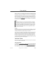
The Send/Receive Tab
Generate a send statement by selecting a PCO, ASP/PDU, constraint,
etc. When you press the Apply button, the statement will be verified by
the selected SDL system. If the verification succeeds, a new send statement will be inserted below the selected behaviour line.
Figure 247: Generating send statements
Generate receives and/or timeout statement(s) below the selected behaviour line by clicking the Generate Receives button. The new row(s)
will all have the same indent level. This indent level will be increased
compared with the previous one.
This operation is only valid when the current selected behaviour line is
a leaf row.
For each retrieved receive statement from the SDL system, a new Constraint is generated if there is no appropriate constraint (a constraint
with a similar value). The new constraint will be named with a unique
name and will be analyzed. This new name is used in the Constraints
Ref column.
July 2003
Telelogic Tau 4.5 User’s Manual
,um-st1
1391
TTCN Link Commands in the TTCN suite
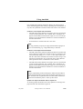
The Timer Tab
Generate a timer statement by selecting Start or Cancel and a timer from
the listbox (optional for Cancel). When you click the Apply button, the
timer statement will be verified against the SDL system. If the verification succeeds, a timer statement will be generated and inserted below
the selected behaviour line. The new behaviour line will have an increased indent level compared to the previous one.
Figure 248: Generating timer statements
The Attachment Tab
When you select an attachment and click Apply, an attachment statement will be generated below the selected behaviour line. The new line
will have an increased indent level compared to the previous one.
The selected test step (the behaviour lines in the behaviour description)
will be verified with the SDL system. The test step must have passed
analysis before this operation.
Note:
TTCN Link does not support attachment parameters.
July 2003
Telelogic Tau 4.5 User’s Manual
,um-st1
1392
Using Autolink
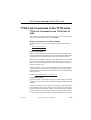
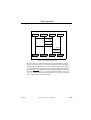
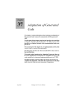
Using Autolink
The generation of a TTCN test suite with Autolink proceeds in several
steps.
User
Specify system
Define paths
Define
configuration
SDL system
MSCs
Autolink
configuration
Modify
constraints
Autolink
Generate
test cases
Test case
representation
Translate MSCs
into test cases
Constraints
TTCN suite
Generate test
suite overview
Generate TTCN
Complete TTCN
test suite
TTCN-MP file
Convert TTCNMP file
Figure 249: Test suite generation with Autolink
July 2003
Telelogic Tau 4.5 User’s Manual
,um-st1
1393
Using Autolink
You start by specifying an SDL system, see “Specifying the SDL System and Performing Other Preparations” on page 1394. Based on this
SDL specification, you generate a Validator application which includes
Autolink.
Next, you define MSC test cases, see “Defining MSC Test Cases” on
page 1396, which describe the purpose of the test cases of your test
suite. They are stored on disk as system level MSCs, that is, MSCs with
only one instance axis for the SDL system and one or more instance axis
for the environment. Test cases may contain test steps which are stored
as separate system level MSCs on disk.
You may also want to define an Autolink configuration, see “Defining
an Autolink Configuration” on page 1411, in order to guide the naming
and parameterization of constraints. Autolink can also be configured to
store test cases into a hierarchy of test groups.
The next step is to generate test cases, see “Translating MSCs into Test
Cases” on page 1416. This can be done either by a state space exploration of the SDL system or by directly translating system level MSCs
into test cases. In any case, the result is an internal representation for
each test case. At the same time, a list of constraints is generated. These
constraints can be renamed and merged, see “Modifying Constraints”
on page 1417. You can also add new constraints manually.
Finally, you generate a TTCN test suite, see “Generating a TTCN Test
Suite” on page 1419, based on the test case representations and the list
of constraints. The test suite is stored on disk in TTCN-MP format. On
UNIX, you can import this file in the TTCN suite; in Windows, you can
simply open it in the TTCN suite. On both platforms, you can convert
the TTCN-MP file to the graphical TTCN format in the Organizer.
On the following pages, the steps will be described in more detail.
Specifying the SDL System and Performing
Other Preparations
Before you start the Validator, directories must be created where you
will store test case and test step representations. If there are no appropriate directories:
•
July 2003
Create one directory for test cases and one directory for test steps in
your working directory.
Telelogic Tau 4.5 User’s Manual
,um-st1
1394
Using Autolink
Specifying the SDL System
You have to specify an SDL system in order to create a Validator. At
minimum, you must specify all channels to the environment of your
system and all signals sent via these channels. With such a minimal
specification, you can use Autolink to translate MSCs directly into
TTCN by using the Translate-MSC-Into-Test-Case command. The advantages and disadvantages of using this command are described in
“Translating MSCs into Test Cases” on page 1416.
Generating and Starting a Validator
When you have specified the SDL system, you can generate and start
the Validator. How to do this is described in “Generating and Starting a
Validator” on page 2323 in chapter 54, Validating a System.
Specifying Directories
Before you start defining test cases and test steps, you have to specify
where they are to be saved:
1. In the Validator, select Autolink: Test Cases Directory from the
Options2 menu.
–
This corresponds to the command Define-MSC-Test-Cases-Directory.
2. In the dialog that will be displayed, select the test case directory that
you previously created and click OK.
3. Select Autolink: Test Steps Directory from the Options2 menu.
–
This corresponds to the command Define-MSC-Test-Steps-Directory.
4. In the dialog that will be displayed, select the test step directory that
you previously created and click OK.
When you later leave the Validator, you can save these values.
July 2003
Telelogic Tau 4.5 User’s Manual
,um-st1
1395
Using Autolink
Defining MSC Test Cases
In Autolink, an MSC test case is derived from a path. A path is a sequence of events that have to be performed in order to go from a start
state to an end state. There are two ways to define MSC test cases:
1. Interactive simulation and manual specification
2. Automatic computation by Autolink (see “Defining MSC Test Cases Automatically - Coverage Based Test Generation” on page 1410)
Defining MSC Test Cases Interactively
The creation of MSC test cases by interactive simulation proceeds in
several steps:
1. Specify the start state of the test case.
If this state is identical to the root of the behavior tree, nothing has
to be done. Otherwise, you must navigate to the desired state, for example by using the Navigator, selecting a previously defined report
or verifying an MSC. Then you set the root to the current state with
the Define-Root Current command.
Note:
Autolink always considers the current root of the behavior tree to be
the start state of a path.
Also note that when a test case is generated, the root has to be the
same as it was at the moment of the test case definition. You have to
keep track of the start state with Print-Path and Goto-Path, for example if you want to leave the Validator temporarily.
2. Navigate through the system to the desired end state.
3. Select MSC: Save Test Case from the Autolink1 menu.
–
This corresponds to the Save-MSC-Test-Case command.
An MSC test case consists of one instance axis for the SDL system and
a separate instance axis for each channel to/from the environment. In
TTCN terms, the single SDL system instance represents the System Under Test (SUT). The environment instances represent the Points of Control and Observation (PCO); PCOs are the interface between the test
system and the SUT.
July 2003
Telelogic Tau 4.5 User’s Manual
,um-st1
1396
Using Autolink
The system level MSC that will be saved contains the observable events
of the path between the start and the end state. Observable events represent the external interaction that takes place between the SDL system
and its environment. (During conformance testing, external interaction
takes place between the implementation and the test system.)
Figure 250 shows an MSC test case.
MSC inres
ISAP1
inres
MSAP2
ICONreq
MDATind
( CR, zero, 0 )
MDATreq
( CC, one, 55 )
ICONconf
IDATreq
(0)
MDATind
(DT, one, 0 )
MDATreq
( AK, one, 55 )
IDISreq
IDISind
MDATind
(DR, one, 55 )
Figure 250: An MSC test case
Incorporating Test Steps in Test Cases
Typically, test cases are structured logically into several parts, for example a preamble, a test body and a postamble. These parts are called
test steps. You may incorporate test steps in a test case by using MSC
references.
July 2003
Telelogic Tau 4.5 User’s Manual
,um-st1
1397
Using Autolink
Figure 251 shows an MSC with two MSC references. Each of the referenced MSCs represents a separate test step; they are called Preamble
and Postamble.
MSC inres2
ISAP1
inres
MSAP2
Preamble
IDATreq
(0)
MDATind
( DT, one, 0 )
MDATreq
( AK, one, 55 )
Postamble
MSC Postamble
MSC Preamble
ISAP1
inres
MSAP2
ICONreq
ISAP1
inres
MSAP2
IDISreq
MDATind
IDISind
( CR, zero, 0 )
MDATreq
( CC, one, 55 )
MDATind
( DR, one, 55 )
ICONconf
Figure 251: An MSC with a preamble and a postamble
Test steps are stored with the same file extension as test cases (.mpr).
They are created in analogy to test cases with Save-MSC-Test-Step.
If you want to create a test case with a preamble and a postamble, several steps are necessary:
1. Make sure that you have specified the directories for test cases and
test steps as described in “Specifying Directories” on page 1395.
July 2003
Telelogic Tau 4.5 User’s Manual
,um-st1
1398
Using Autolink
2. Set the root of the state space to the start state of the test case by using the command Define-Root Current.
3. Navigate to the end of the path of the preamble.
4. Use Save-MSC-Test-Step to save the preamble.
5. Set the root of the state space to the current state by using the command Define-Root Current.
6. Navigate to the end of the path of the test body.
7. Use Save-MSC-Test-Case to save the test case/test body.
8. Set the root of the space to the current state.
9. Navigate to the end state of the test case.
10. Use Save-MSC-Test-Step to save the postamble.
11. Add two MSC references manually to the MSC test case with the
MSC Editor.
Alternatively, you may create a single MSC test case and split the file
into preamble, test body and postamble afterwards.
Test steps may refer to other test steps, but not to test cases. During test
case generation, Autolink keeps track of the nested structure of test cases and test steps.
Note:
When Autolink generates test cases (see Generate-Test-Case and
Translate-MSC-Into-Test-Case), the semantics of MSC references
and MSC reference expressions are different from the semantics
given in the ITU-T Recommendation Z.120!
Autolink requires that a test step is completely evaluated before the
next test step starts, i.e. it synchronizes among references, whereas
Z.120 considers MSC references as macros which do not have to be
evaluated as a unit.
With regard to Figure 251, this means that all signals of the test body
in mi_inres2 have to be evaluated before the postamble starts.
July 2003
Telelogic Tau 4.5 User’s Manual
,um-st1
1399
Using Autolink
Using Timers
Autolink supports test suite timers. There are three types of timers
which are commonly needed in test sequences:
1. A global timer is specified to guarantee that test cases end even if
they are blocked during execution due to an error. By default, Autolink generates a global timer T_Global automatically and starts it
at the beginning of each test case. At the end of each test sequence,
T_Global is cancelled. The automatic generation of timers can be
enabled and disabled with the Define-Global-Timer command.
2. A delaying timer is used to delay the sending of a signal from the
tester to the SUT. This may be done for several reasons; for example, the sending is delayed on purpose to specify an invalid behavior
of the environment.
3. A guarding timer is used to check that the SUT sends a signal within
a predefined amount of time.
Delaying and guarding timers have to be specified manually on the environment instances in test case MSCs. As an example, the MSC in
Figure 252 contains a guarding timer T_Guard on instance ISAP1 and a
delaying timer T_Wait on instance MSAP2.
T_Guard is set prior to sending a signal to the SUT and reset after the
corresponding response from the SUT. If message ICONconf is received in time, test execution proceeds normally. Otherwise, a timeout
of T_Guard will be caught in the Default Dynamic Behavior description
and lead to a fail verdict.
The setting of timer T_Wait is followed immediately by a timeout event,
causing the tester to delay the sending of message MDATreq.
.
Note:
Test suite timers are part of the environment of the SUT. Correspondingly, there is no explicit relation between these timers and
any timers which might be used within the system. Autolink simply
translates timer set events on environment instances into TTCN
START operations, timer reset events into TTCN CANCEL operations
and timeout events into TTCN TIMEOUT events. However, timer
events on any MSC instance belonging to the SUT are not translated
into TTCN statements.
July 2003
Telelogic Tau 4.5 User’s Manual
,um-st1
1400
Using Autolink
MSC guarddelay
ISAP1
inres
MSAP2
T_Guard
(10 ms)
ICONreq
MDATind
T_Wait
(PIX_Wait ms)
(CR, ,)
MDATreq
ICONconf
( CC, one, 55 )
IDISreq
IDISind
MDATind
( DR, one, )
Figure 252: Test case MSC with guarding and delaying timer
Autolink creates timer declarations automatically from the information
which it finds in the test case MSCs. From the MSC in Figure 252, Autolink generates a declaration for timer T_Guard with the default duration set to 10 and ms as unit. Correspondingly, the default duration for
T_Wait is set to the test suite parameter PIX_Wait and its unit is set to
ms as well. Autolink also generates a declaration for PIX_Wait.
This implicit declaration mechanism is convenient if the test suite consists of only one test case. If there are more test cases using timers, declaration conflicts may arise since timers are declared globally for the
test suite. In order to solve this problem, Autolink provides the DefineTimer-Declaration command to explicitly declare test suite timers. Explicit timer declarations can not be modified by implicit declarations. It
is therefore recommended to define all timer declarations explicate before test case computation starts. In that case, only the timer name must
be provided for timer set events in the test case MSCs. The duration is
optional (Autolink uses the duration value if it is not empty and different
from the default duration specified in the declaration). Finally, the unit
can be omitted from the test case MSCs if an explicit declaration exists.
July 2003
Telelogic Tau 4.5 User’s Manual
,um-st1
1401
Using Autolink
The use of test suite timers and their declaration is explained in more detail in “Test Suite Timers” on page 1445. With respect to timers, the
TTCN output generated by Autolink depends on the test architecture.
This is also discussed in “Test Suite Timers” on page 1445.
Defining Multiple Test Cases by HMSC Diagrams
HMSC diagrams can be used to illustrate the relationship between various test cases. For example, even though test cases normally have different test purposes, they might share the same preamble and postamble. This commonness can be graphically expressed by the use of an
HMSC diagram such as the one in Figure 253.
Note:
HMSCs are not supported by Generate-Test-Case but only by
Translate-MSC-Into-Test-Case.
MSC Test
1(1)
Preamble
Valid
Invalid
Inopportune
Postamble
Figure 253: Three test cases described by one HMSC diagram
When the HMSC Test is taken as input, Autolink will create three test
cases which consist of the test steps Preamble/Valid/Postamble, Preamble/Invalid/Postamble and Preamble/Inopportune/Postamble.
The general interpretation of HMSCs can be described by a simple rule:
Autolink generates a separate test case for each possible path through
an HMSC. Of course, HMSCs may have more than one node with several outgoing edges, resulting in a potentially large number of test cases.
July 2003
Telelogic Tau 4.5 User’s Manual
,um-st1
1402
Using Autolink
Note:
Autolink does not translate loops directly into equivalent constructs
in TTCN. Instead it handles loops by unrolling. Therefore, you
should not introduce loops in HMSC diagrams.
All test cases need to have unique names. With regard to the HMSC Test
in Figure 253, the resulting test cases will be named Test_Valid,
Test_Invalid and Test_Inopportune. Whenever there is a branch in the
HMSC, the name of the succeeding MSC reference is postfixed to the
name of the top-level MSC (separated by ‘_’).
Describing Indeterministic Behaviour by Inline and
Reference Expressions
Sometimes, a system under test may not behave deterministically. For
example, there may be unpredictable failures. A tester should be able to
handle such situations. By the use of inline expressions and MSC reference expressions, it is possible to describe test cases where the tester reacts flexibly depending on the system behaviour.
If some of your test cases only differ slightly at some point in the test
case, you may also use inline and reference expressions to describe different behaviour of the tester. In that case, Autolink generates separate
test cases.
Autolink supports the following operators in MSC expressions:
•
The alternative operator (alt) is suitable for the description of situations where the continuation of a test case depends on the former
output of the system. If both alternatives start with a signal sent from
the system to the tester (i.e. the environment), Autolink will generate two branches within a single test case.
On the other hand, the operator may also be used to specify two alternative test sequences. If both alternatives start with a signal sent
from the tester (environment) to the system, Autolink will generate
two distinct test cases.
•
July 2003
The optional operator (opt) can be used, e.g., to accept signals
which may or may not be sent by the system or to react to unexpected signals in a way that the test case can be continued normally afterwards.
Telelogic Tau 4.5 User’s Manual
,um-st1
1403
Using Autolink
•
The exception operator (exc) is intended to be used for error handling. An exception expression may contain signals which prevent
the test system from continuing the regular test execution. In MSC
ConnectionRequest (Figure 254 on page 1404), the reception of signal IDISind immediately stops the test case. Optionally, an exception includes a sequence of signals which bring the system under
test back into a stable testing state. An exception always results in
an “INCONC” verdict.
•
The loop operator (loop) can be used to describe the iterative execution of a (portion of a) test case. As in HMSCs, Autolink does not
translate loop expressions directly into equivalent constructs in
TTCN. Instead, it handles loops by unrolling. If no upper loop
boundary is given, the loop is evaluated up to three times.
•
Finally, the sequence operator (seq) can be used within reference
expressions in order to state that one test step follows another.
Note:
Autolink does not support the parallel (par) and substitution
(subst) operator within inline and reference expressions.
MSC ConnectionRequest
ISAP1
inres
ISAP2
ICONreq
1
exc
IDISind
1
ICONind
ICONresp
ICONconf
Figure 254: Test case with exception handling
July 2003
Telelogic Tau 4.5 User’s Manual
,um-st1
1404
Using Autolink
Of course, the usage of the different operators is not restricted to the applications described above. On the other hand, not all MSCs containing
inline or reference expressions may describe sensible test cases.
Synchronization among MSC expressions
As mentioned before, Autolink synchronizes at the beginning and the
end of MSC references. This modification of the semantics given in the
MSC standard is motivated by the ability to consider separate MSCs as
different test steps. If we cannot guarantee that all events in one MSC
are evaluated before the next MSC is entered, we cannot draw a line between two subsequent test steps.
MSC reference expressions are a generalization of plain MSC references. Autolink generates distinct TTCN test steps for each of the MSCs
involved in the expression. For that reason, it makes sense to synchronize at MSC references, too.
When it comes to inline expressions it is not really necessary to synchronize at their beginning and their end. However, for consistency Autolink synchronize at inline expressions, as well.
There are situations where synchronization among inline expressions is
preferable, whereas in other cases the TTCN output and Autolink’s error messages may be confusing.
In Figure 255, two examples are given. For MSC Sync1, Autolink will
generate a test case where either ReceiveB or ReceiveC is anticipated
before the test execution proceeds with SendD. If Autolink did not synchronize at the end of the alternative expression, SendD would be sent
before ReceiveB (please note that Autolink prioritizes send events).
Moreover, since both alternatives are combined in a single behaviour
tree, SendD would erroneously become an alternative to ReceiveC!
Unfortunately, there are also cases where synchronization results in unexpected TTCN test cases. For the second MSC in Figure 255, Autolink
will try to generate the following event tree:
Env1 ! SendA
Env2 ? OptReceiveB
Env1 ! SendC
Env2 ? ReceiveD
Env1 ! SendC
Env2 ? ReceiveD
July 2003
Telelogic Tau 4.5 User’s Manual
,um-st1
1405
Using Autolink
Of course, Autolink detects that there is a conflict among the two alternatives OptReceiveB and SendC and will print a warning.
Whenever Autolink issues a warning, you should carefully inspect your
MSC test case definition. For example, when MSC Sync2 is interpreted
as a test case, it is unclear how long a tester shall wait until it outputs
SendC. On the other hand, if OptReceiveB is not logically caused by
SendA or may received at any time, a possible solution would be to
move SendC above the optional expression. In this case, no conflict
arises.
Synchronizing Test Events with Conditions
The messages in MSCs are only partially ordered. If a test generation
tool would generate all possible test sequences, then send events could
appear as alternatives to receive events in TTCN test cases, making
them indeterministic. To solve this problem, three solutions are possible:
1. Events received by the tester are prioritized over events sent to the
SUT.
2. Events sent to the SUT are prioritized over events received by the
tester.
3. All messages in the MSC are evaluated from top to bottom. In that
case, only one sequence of test events is generated.
The first alternative may lead to deadlocks and therefore it is not supported by Autolink. Alternative three may be selected with the DefineAutolink-Generation-Mode command.
By default, Autolink uses the second alternative and prioritizes events
which are sent from the test system to the SUT over events which are
received by the tester from the SUT.
July 2003
Telelogic Tau 4.5 User’s Manual
,um-st1
1406
Using Autolink
MSC Sync1
Env1
SUT
Env2
SendA
1
alt
ReceiveB
1
ReceiveC
1
SendD
ReceiveE
MSC Sync2
Env1
SUT
Env2
SendA
1
opt
OptReceiveB
1
SendC
ReceiveD
Figure 255: Synchronization among inline expression
July 2003
Telelogic Tau 4.5 User’s Manual
,um-st1
1407
Using Autolink
MSC Sync_Example
A
B
SUT
C
Request
(B)
Indication
(A)
Response
Confirmation
Request
(B)
BusyIndication
Figure 256: Synchronization example 1
However, there are situations where this “send immediately” strategy
leads to incorrect test cases. Consider the following small example: A
calls B, B accepts the call, then C tries to call B and gets a busy signal.
A corresponding MSC test purpose description would look similar to
the one in Figure 256. What test sequence will Autolink generate? First,
the tester will send Request(B) to the SUT through PCO A. Next, Request(B) will be sent to the SUT through PCO C, since this is the next
send event on any of the tester instances.
July 2003
Telelogic Tau 4.5 User’s Manual
,um-st1
1408
Using Autolink
MSC Sync_Example_2
A
B
SUT
C
Request
(B)
Indication
(A)
Response
Confirmation
SyncPoint
Request
(B)
BusyIndication
Figure 257: Synchronization example 2
Most likely, this is not what you have anticipated intuitively; the tester
should send the second Request(B) only after it has received Confirmation through PCO A. This is where explicit synchronization with
conditions comes in. Figure 257 contains the same MSC as Figure 256,
with a global condition added between the reception of Confirmation
at PCO A and the sending of Request(B) through PCO C. If the Autolink synchronization option is turned on (with Define-ConditionCheck), then events below the condition can only be executed if all
events above the condition have been executed as well. The condition
effectively becomes a synchronization point. In the example, the sending of Request(B) through C will be delayed until Confirmation has
been received at PCO A. The name in the condition is required by the
ITU Recommendation Z.120, however it is only considered as a comment and does not have any semantics.
July 2003
Telelogic Tau 4.5 User’s Manual
,um-st1
1409
Using Autolink
.
Note:
The condition check option also applies to the MSC verification
function of the Validator.
Listing and Clearing Test Cases and Test Steps
•
Use List-MSC-Test-Cases-And-Test-Steps for listing all MSC test
cases and test steps that are defined in the current test cases and test
steps directories.
•
Use Clear-MSC-Test-Case to delete an MSC test case.
•
Use Clear-MSC-Test-Step to delete an MSC test step.
Note:
Autolink distinguishes between the MSC test case name (which is
the name of the system level MSC) and the name of the file on disk
that contains the MSC test case. Usually, these names are identical
except for the file extension.
When accessing the test cases and the test steps directory, Autolink
always refers to the file names, meaning that you also have to specify the file extension (either .mpr or .msc)
Defining MSC Test Cases Automatically Coverage Based Test Generation
One common method to generate a test suite is to select a number of test
cases which, taken together, obtain a high coverage of the SDL specification. Ideally, this coverage should be 100%. In that case, every SDL
symbol in the specification is executed at least once during test generation.
Autolink provides a special state space exploration technique, called
Tree Walk, which is optimized for finding paths through the state space
of the SDL specification that result in a high SDL symbol coverage.
Tree Walk combines the advantages of both the depth-first and breadthfirst search strategy - it is able to visit states located deep in the reachability graph and to find a short path to a particular state at the same
time.
•
July 2003
To use Tree Walk, apply the Tree-Walk command.
Telelogic Tau 4.5 User’s Manual
,um-st1
1410
Using Autolink
The execution of Tree Walk is controlled by two options:
1. The maximum computation time (specified in minutes)
2. The targeted coverage (specified in percent)
When Tree Walk is used, it generates a report for each sequence of transitions in the state space that increases the number of visited SDL symbols. These reports can be converted into system level MSCs with the
command Save-Reports-as-MSC-Test-Cases.
Defining an Autolink Configuration
Autolink offers a special language for defining rules for the naming and
parameterization of constraints, the introduction of test suite parameters
and constants, and the distribution of test cases and test steps into test
groups.
•
To specify Autolink configuration rules, use the command DefineAutolink-Configuration.
While it is possible to define an Autolink configuration on the fly at the
Validator command prompt, it is better to write a command file which
includes the configuration.
•
To load this file, use the Include-File command.
The command corresponds to the menu choice Configuration: Load
in the Autolink2 menu.
•
To remove a loaded configuration, use the Clear-Autolink-Configuration command.
•
To display the current configuration, use the Print-Autolink-Configuration command.
•
To save a configuration, use the Save-Autolink-Configuration command.
See also:
July 2003
•
“Translation Rules” on page 1421 for an introduction to translation
rules.
•
“Test Suite Structure Rules” on page 1427 for the methodology for
test suite structure rules.
Telelogic Tau 4.5 User’s Manual
,um-st1
1411
Using Autolink
•
“Syntax and Semantics of the Autolink Configuration” on page
1433 for a detailed description of the configuration language.
Computing Test Cases
Once you have defined a set of MSC test cases, you can compute internal test case representations for each MSC test case.
•
To compute MSC test cases, use the Generate-Test-Case command.
A bit-state exploration will be started which aims at finding all possible sequences of observable events that conform to the MSC. In
addition, Autolink searches for inconclusive events. These are
events that represent deviations from the behavior specified in the
MSC test case, but which are valid alternatives according to the
SDL specification.
Either a single test case or a set of test cases in the current test cases directory may be generated at the same time, depending on the parameter
of Generate-Test-Case. If an already generated test case is regenerated,
its former internal representation and its corresponding constraint definitions are replaced.
Note:
If the SDL specification is not detailed enough in the sense that it
does not model the signal flow in a given MSC, the generation of the
test case fails. MSCs which cannot be verified can still be converted
into test cases with the Translate-MSC-Into-Test-Case command,
which is described in “Translating MSCs into Test Cases” on page
1416.
Inline expressions, MSC reference expressions and HMSC diagrams are not supported by Generate-Test-Case. (However, you can
use these structural concepts for Translate-MSC-Into-Test-Case.) If
you want to generate test cases based on HMSCs, you have to transform your HMSC diagrams into basic MSCs first. You can do this
by verifying the HMSCs and saving all MSC Verification reports as
MSC test cases (command Save-Reports-as-MSC-Test-Cases).
With complex systems, test generation may take a while. To avoid timeconsuming test generation failures, you should verify all MSCs first.
•
July 2003
To verify all MSC, use the Verify-MSC command.
Telelogic Tau 4.5 User’s Manual
,um-st1
1412
Using Autolink
In most cases, MSC verification takes only a fraction of the time
needed for test generation.
Listing and Clearing Generated Test Cases
•
You can list all generated test cases with the List-Generated-TestCases command.
•
You can clear all generated test cases with the Clear-GeneratedTest-Case command.
Displaying and Saving the Internal Representation
•
You can display the internal representation of a generated test case
– without having to save the test suite and start the TTCN suite –
with the Print-Generated-Test-Case command.
•
You can save an internal test case representation with the Save-Generated-Test-Case command.
•
You can load an internal test case representation back into memory
with the Load-Generated-Test-Cases command.
This makes it possible to distribute the generation of a set of test cases
to several computers. When all test cases have been generated and saved
in individual files, they can be reloaded on a single machine and saved
as a complete test suite.
State Space Exploration Parameters
There are several parameters which influence the state space exploration:
•
You can set the maximum search depth with the Define-AutolinkDepth command (default value is 1000).
If the search depth is set too low, this may result in incomplete pass
paths. Since the maximum search depth normally has no impact on
the performance of the state space search, it is recommended that
you always use a large value (> 1000).
•
You can resize the hash table with the Define-Autolink-Hash-Table-Size command (default size is 1,000,000 bytes).
Increasing the hash table size may be necessary if the SDL system
is rather complex.
July 2003
Telelogic Tau 4.5 User’s Manual
,um-st1
1413
Using Autolink
•
Normally, Autolink changes the regular Validator state space options, because the default values of the Validator are not sufficient
for generating correct test cases.
For example, for the Inres protocol specification, the following
commands are issued:
Define-Scheduling All
Define-Transition Symbol-Sequence
Define-Symbol-Time Zero
Define-Priorities 2 1 3 2 2
Define-Channel-Queue ISAP1 On
Define-Channel-Queue MSAP2 On
Define-Max-Input-Port-Length 10
Other SDL systems require different Define-Channel-Queue commands.
Autolink automatically resets the original options when a test case
generation is finished. Therefore, previously defined reports are still
valid (unless they were generated by verifying an MSC).
If you do not want to use the default settings for any reason, use the
Define-Autolink-State-Space-Options Off command. This disables
the automatic setting of Autolink’s default options.
Test Case Generation Messages
After the generation of a test case, some warnings or error messages
may be displayed:
•
Error: Autolink did not find any complete pass paths.
No test case is generated.
This message appears if no final TTCN pass verdict has been assigned to any event in the internal test case representation.
The most common reason for test generation failure is that the MSC
does not describe a valid trace of the SDL system. Hence, before
running Autolink, you should check that the MSC test case can indeed be verified using command Verify-MSC.
The error message above may also appear if the maximum search
depth is set too low. Check the state space exploration statistics
which are displayed by Autolink at the end of the test case generation. If the number of truncated paths is greater than zero, you
should increase the maximum search depth. The required value for
July 2003
Telelogic Tau 4.5 User’s Manual
,um-st1
1414
Using Autolink
the search depth depends both on the length of the test case and on
the selected state space options of the Validator.
Autolink may also fail if you do not specify the signal parameters in
the MSC test cases, but instead use global test values. Make sure
that at least all signals sent into the system are fully specified in the
MSC.
•
Warning: Incomplete pass path found.
The first event X on the incomplete branch
gets an ’INCONC’ verdict.
This message is displayed if a path in the state space is pruned before a final TTCN pass verdict has been assigned to an observable
event. (Note that in this context a pass path refers to the internal test
case representation whereas otherwise, a path refers to the state
space of the SDL system.) If this happens, the first event X of the
incomplete subtree is reassigned as a TTCN inconc verdict, and the
rest of the subtree is discarded.
The reasons for a pass path being pruned are numerous. The system
level MSC may not be verifiable, for example if the state space is
too restricted, or there may be a path in the state space of the SDL
system that only partially verifies the MSC. A common problem is
the maximum search depth being too low (see above).
•
Warning: Alternative events found for send event.
Inconclusive events are deleted.
For test generation, it is assumed that signals which can be sent to
the system are sent instantaneously. Therefore, alternatives to send
events are not desired.
With the default options of Autolink, this message should not appear. If you use your own Autolink options, check whether Input
from ENV has the highest priority. To correct the problem, you
should use the Define-Priorities command with parameters X1 1 X2
X3 X4, where Xi > 1.
•
Warning: No translation rule can be applied to the
following signal: <Signal Name>
If you define an Autolink configuration containing translation rules,
Autolink assumes that you want to map all SDL signals onto constraints with the help of user-defined rules. Hence, you will be
July 2003
Telelogic Tau 4.5 User’s Manual
,um-st1
1415
Using Autolink
warned if there is a signal in a test case to which no translation rule
can be applied.
•
Warning: There are events following an event with final ‘PASS’ verdict.
When the MSC test case has been simulated completely, the SDL
system was not yet in a stable state. Instead, it sent out one or more
additional signals which were not specified in the MSC test case.
You should carefully review your test specification, since during a
test campaign you may not be able to successfully execute another
test case after the execution of the faulty test case.
Translating MSCs into Test Cases
If an SDL system is not fully specified, some or all MSCs may not be
converted into test cases if you use the Generate-Test-Case command.
Instead, you can use the Translate-MSC-Into-Test-Case command to
translate MSCs directly into the same internal test case format which is
used for test cases generated by state space exploration. Therefore, you
can use all commands related to listing, displaying, removing, saving
and loading of test cases (introduced in “Computing Test Cases” on
page 1412) with directly translated test cases as well.
Furthermore, all rules for constraint naming (see “Translation Rules” on
page 1421) and test grouping (see “Test Suite Structure Rules” on page
1427) apply to translated test cases, too.
Note:
Since the translation of MSCs into test cases does not perform a state
space exploration, there is no guarantee that the MSCs and hence the
test cases describe valid traces of the specification or the implementation, respectively. Instead, the validity of the test cases has to be
assured by the developer. Furthermore, no inconclusive events can
be computed during MSC translation. Therefore, the resulting test
cases return a fail verdict for any deviation from the behavior described in the MSC.
Either a set of test cases in the current test cases directory or just a single
one may be translated at the same time, depending on the parameter of
Translate-MSC-Into-Test-Case. If an already translated test case is retranslated, its former internal representation and its constraint definitions are replaced.
July 2003
Telelogic Tau 4.5 User’s Manual
,um-st1
1416
Using Autolink
Two different algorithms are available for MSC translation: With the
Define-Autolink-Generation-Mode command, you can choose the semantics used to interpret MSCs during translation. By default, Autolink
uses the standard semantics of MSC. If the generation mode is set to “total ordering”, then the sequence of input and output events in the MSC
is determined straight from top to bottom. If there are two events on different environment instances, Autolink evaluates the event which is
closest to the top of the MSC first.
Note:
For test generation with state space exploration (using the GenerateTest-Case command), total ordering is not supported.
MSC into TTCN Translation Messages
After the generation of a test case, some warnings or error messages
may be displayed:
•
Error: No test case could be generated.
Please check whether the MSC contains separate instance axes for each channel to the environment.
The Translate-MSC-Into-Test-Case command does not support the
translation of MSCs with only one instance axis for the environment. Use MSCs with a separate instance axis for each channels to
the environment (i.e. for each PCO).
•
Warning: No translation rule can be applied to the
following signal: <Signal Name>
If you define an Autolink configuration containing translation rules,
Autolink assumes that you want to map all SDL signals onto constraints with the help of user-defined rules. Hence, you will be
warned if there is a signal in a test case to which no translation rule
can be applied.
Modifying Constraints
It is highly recommended that you specify constraints naming and parameterization rules in an Autolink configuration file. Otherwise, a generic name of the form <Test case name>_<three digit number> is assigned to each constraint during test case generation. However in the
latter case, you will probably find it useful to modify the constraints
generated by Autolink.
July 2003
Telelogic Tau 4.5 User’s Manual
,um-st1
1417
Using Autolink
•
Use the Rename-Constraint command to change the name of a constraint.
Besides renaming a constraint, it is also possible to merge two constraints. Do this by giving a constraint the same name as another
one. Then you will have to select which of the two signal definitions
should be kept (unless they are identical). There is one restriction:
Constraints with formal parameters cannot be overwritten by other
constraints.
See also “Translation Rules” on page 1421.
•
Use the Merge-Constraints command to merge two constraints by
potentially introducing formal parameters.
If the original constraints are used in test cases, their constraint references will be updated. This means that the concrete signal parameters (which were replaced by formal parameters) will be moved to
the constraint references.
Note:
If you rename a constraint or merge two constraints, the internal test
case descriptions are updated, too. The links between the events in
the test cases and their corresponding constraints remain consistent.
•
Use the Define-Constraint command to add new constraints to the
current list of constraints.
If a constraint with the same name but a different signal definition
already exists, you will have to choose what to do – rename the new
constraint, overwrite the old constraint or remove the new definition.
July 2003
•
Use the Parameterize-Constraint command to replace concrete signal parameter values in a constraint by formal (symbolic) parameters. If the parameterized constraint is used in a test case, the parameter value is not lost, but maintained in the constraint references of
the referring test cases instead.
•
Use the Clear-Constraint command to delete a constraint.
•
Use the List-Constraints command to list all currently defined constraints.
•
Use the Save-Constraint command to save one or all constraints.
Telelogic Tau 4.5 User’s Manual
,um-st1
1418
Using Autolink
•
Use the Load-Constraints command to reload saved constraints.
Generating a TTCN Test Suite
•
Use the Save-Test-Suite command to save a test suite in a TTCNMP file.
The internal representations of the test cases will be kept in memory
in order to allow you to save test suites in different formats.
•
There are two fundamentally different formats to save test suites:
“Traditional” TTCN and concurrent TTCN. To switch between
these formats, use the Define-Concurrent-TTCN command. For a
detailed description of the concurrent TTCN format, see “Concurrent TTCN” on page 1440.
•
By default, constraints are stored as ASN.1 ASP constraints, but before you generate a test suite, you may change an option to have
them stored as ASN.1 PDU constraints instead. To do this, use the
Define-TTCN-Signal-Mapping command. You are also allowed to
select the correct type of constraint for each signal individually by
adding rules to an Autolink configuration (see “Defining ASP and
PDU Types” on page 1431).
•
There are three possible output formats for test steps. Use the Define-TTCN-Test-Steps-Format command to select an output format:
–
One possibility is to store the test steps of a single test case as
local trees. If a test step is used several times, only one behavior
description is generated.
–
Test steps can also be stored globally in the test step library. If
a test step is used several times in different test cases, only one
behavior description is generated.
–
A third alternative is to generate “flat” test cases by including
the events of the test steps directly in the test case dynamic behavior descriptions. In this case, no information about test steps
is put into the TTCN test suite.
Note:
A test step that is used in several places may lead to trees with different inconclusive events or different verdicts. In this case, they
will be given new, unique names.
July 2003
Telelogic Tau 4.5 User’s Manual
,um-st1
1419
Using Autolink
Preliminary Pass Verdicts
Test cases that are structured into preamble, test body and postamble
will automatically be assigned preliminary pass verdicts at the end of
the test body. However, test cases can contain an arbitrary number of
MSC references (and hence test steps). Therefore, preliminary pass verdicts will be assigned to all events that are directly followed by the last
top-level MSC reference in the test case. The preliminary pass verdicts
will only be assigned if no event follows the last MSC reference. The
event to which a preliminary pass verdict is assigned may appear within
the test body as well as within a test step.
Test Suite Generation Messages
During the saving of a test suite, some warnings or error messages may
be displayed:
•
Warning: Test step <TS> resulted in different trees.
The trees are renamed to ‘<TS>_1’, ‘<TS>_2’, etc. in
the test suite.
If an MSC test step is reused in several test cases, the resulting
TTCN test steps may be different. Typically, this warning appears
if a test step is used as a preamble in one test case and then again as
a complete test case by itself. In the latter case, a final pass verdict
is assigned to the test case, while in the former one it is not.
•
Warning: No test suite structure rule defined for test
case/step ‘<TestCaseName/TestStepName>’.
If you define an Autolink configuration containing test suite structure rules, Autolink assumes that you want to place all test cases/steps in test groups defined by the test suite structure rules.
Hence, you will be warned if there exists a test case/step to which
no rule can be applied.
•
Warning: Test suite parameter/constant ‘<Name>’ is
not unique.
It is renamed to ‘<Name>_1’, ‘<Name>_2’, etc. in the
test suite.
By using translation rules (see “Translation Rules” on page 1421)
you can introduce test suite parameters and constants. These parameters and constants are checked for consistency in a similar way as
test suites. With the warning above, Autolink informs you that it had
to rename test suite parameters/constants in order to resolve naming
conflicts.
July 2003
Telelogic Tau 4.5 User’s Manual
,um-st1
1420
Using Autolink
Translation Rules
In “Modifying Constraints” on page 1417, you have learned how to
change constraints. However, assigning sensible names to automatically generated constraints is a tedious task. Especially if you have to refine the SDL specification and then to repeat the test generation process,
there is a lot of manual work. Moreover, the number of generated constraints may become very large if you do not use constraint parameterization.
In order to address these problems and some additional issues, you can
specify so-called translation rules. These rules control the look of a test
suite with regard to the following items:
1. Naming of constraints
2. Parameterization of constraints
3. Replacement of signal parameter values by wildcards in a constraint
declaration table
4. Introduction and naming of test suite parameters and test suite constants
Translation rules build one integral part of an Autolink configuration
(see also “Test Suite Structure Rules” on page 1427). Before you start
the test generation, you can develop an Autolink configuration file that
contains a Define-Autolink-Configuration command. The set of translation rules which tell Autolink how to construct constraints and treat
parameters for particular signals, are provided as a kind of long parameter to this command.
For some examples, see “Examples of Translation Rules” on page 1421.
More information can be found in “Defining an Autolink Configuration” on page 1411 and “Syntax and Semantics of the Autolink Configuration” on page 1433.
Examples of Translation Rules
A typical translation rule may look like this:
Example 257 –––––––––––––––––––––––––––––––––––––––––––––––
TRANSLATE MDATind
CONSTRAINT NAME "C_" + $0
PARS $1="Type"
July 2003
Telelogic Tau 4.5 User’s Manual
,um-st1
1421
Using Autolink
END
––––––––––––––––––––––––––––––––––––––––––––––––––––––––––
Example 257 explains how signal MDATind is translated into an suitable
TTCN constraint. The rule above states that the name of a constraint for
signal MDATind consists of the concatenation of text "C_" and the
“nullth” parameter – which is the name of the signal itself. Therefore,
signal MDATind is translated into a constraint called C_MDATind.
Additionally, the first parameter of the signal (referred to by $1) becomes a parameter of the constraint. The name of the formal parameter
is Type. It is printed both in the Constraint Name line and the Constraint Value section of the constraint declaration table. The actual parameter of the constraint is printed in the dynamic behavior table of each
test case that uses this constraint.
A constraint declaration table for signal MDATind is shown in
Figure 258.
Figure 258: A constraint declaration with a formal parameter
It is also possible to define a single translation rule for more than one
signal. This is especially useful if similar signals exist which can be
treated in the same way.
July 2003
Telelogic Tau 4.5 User’s Manual
,um-st1
1422
Using Autolink
Example 258 –––––––––––––––––––––––––––––––––––––––––––––––
TRANSLATE MDATind | MDATreq
CONSTRAINT NAME “C_” + $0
PARS $1=”Type”
END
––––––––––––––––––––––––––––––––––––––––––––––––––––––––––
If either MDATind or MDATreq is identical to the signal for which a constraint is to be created during test generation, the rule in Example 258 is
applied. The value of $0 depends on the name of the actual signal investigated at run-time. Since the first signal parameter is always to be
replaced by the formal parameter Type, the rule is only valid if each of
the alternative signals, i.e. MDATind, and MDATreq, has at least one parameter. When parsing an Autolink configuration, all translation rules
are checked automatically for validity.
Constraint names may not only be based on texts and signal names.
They can also depend on signal parameters. In a translation rule, a signal
parameter is referred to by its number, prefixed with a dollar character
($). (Note that Autolink only supports parameters on the top level – it is
not possible to refer to a component of a nested parameter.)
In some cases, it is not desirable to use the value of a signal parameter
directly as part of a constraint name. For example, a protocol engineer
might encode complicated signal information with abbreviations or
numbers. But for the TTCN output, parameter values should be mapped
onto more meaningful expressions.
Therefore, you may define functions which take an arbitrary number of
parameters and map them onto text. In Example 259, the value of the
first parameter of signal MDATind is passed to function PDUType. Depending on the concrete parameter value, which occurs during test case
generation, the function returns a text. This text forms the second part
of the constraint name.
July 2003
Telelogic Tau 4.5 User’s Manual
,um-st1
1423
Using Autolink
Example 259 –––––––––––––––––––––––––––––––––––––––––––––––
TRANSLATE MDATind
CONSTRAINT NAME "Medium_" + PDUType($1)
END
FUNCTION PDUType
$1 == "CR" : "Ind_Connection_Request"
| $1 == "AK" : "Ind_Acknowledge"
| $1 == "DR" : "Ind_Disconnection_Request"
| TRUE
: "Indication"
END
––––––––––––––––––––––––––––––––––––––––––––––––––––––––––
Note:
In a translation rule, $i refers to the i-th parameter of the signal for
which a constraint is created. However in a function, $i denotes
the i-th parameter which was passed to the function.
You may define complex rules whose evaluation is guarded by conditions. This is illustrated in Example 260.
Example 260 –––––––––––––––––––––––––––––––––––––––––––––––
TRANSLATE "MDATind"
IF $1 == "CR" THEN
CONSTRAINT NAME "Medium_Connection_Request"
END
IF $1 == "AK" AND $2 == "zero" THEN
CONSTRAINT NAME "Medium_Acknowledge_Zero”
END
CONSTRAINT NAME “Medium_Indication”
PARS $1=”Type”
END
––––––––––––––––––––––––––––––––––––––––––––––––––––––––––
Conditional translations can be defined by IF-statements. Only if the
condition(s) following the IF keyword is/are satisfied, the constraint is
built according to the subsequent specification. A translation rule can
contain several IF-clauses. The first clause which condition is satisfied
(or which does not have an IF statement at all) is chosen for translation.
In the example above, signal MDATind is translated into a constraint
called Medium_Connection_Request if the first signal parameter
equals CR, and to a constraint called Medium_Acknowledge if the first
two signal parameters equal AK and zero respectively. If neither condition is satisfied, the unconditioned section is evaluated. In this case, a
constraint with name Medium_Indication and formal parameter Type
July 2003
Telelogic Tau 4.5 User’s Manual
,um-st1
1424
Using Autolink
is created. Note that the parameter definition is not taken into account if
any of the former IF-conditions is satisfied!
Sometimes, it is useful to indicate that a specific signal parameter is irrelevant. For example, assume that if the first parameter of signal MDATind is CR, the values of the second and third parameter can be ignored.
Hence, you can replace them by wildcards in a constraint table. In
Example 261, a MATCH statement is added that tells Autolink to replace
the values of the signal parameters 2 and 3 by asterisks. The resulting
constraint table is displayed in Figure 259.
Example 261 –––––––––––––––––––––––––––––––––––––––––––––––
TRANSLATE "MDATind"
IF $1 == "CR" THEN
CONSTRAINT NAME "Medium_Connection_Request"
MATCH $2="*", $3="*"
END
CONSTRAINT NAME “Medium_Indication”
PARS $1=”Type”
END
––––––––––––––––––––––––––––––––––––––––––––––––––––––––––
Note:
The application of TTCN matching mechanisms is only valid for receive events. Hence, you are not allowed to apply the MATCH statement to signals that become send events in TTCN.
Figure 259: A constraint table with TTCN matching expressions
Translation rules also allow to introduce test suite parameters and constants. Test suite constants are useful if a concrete parameter value does
not give any clues about its meaning and hence should be replaced globally by a more meaningful name. Test suite parameters should be introduced if signal parameter values are implementation dependent. By
defining a test suite constant/parameter, a concrete signal parameter
July 2003
Telelogic Tau 4.5 User’s Manual
,um-st1
1425
Using Autolink
value in a constraint table is replaced by a symbolic constant. The assignment of concrete values to symbolic test suite constants/parameters
is made in additional TTCN tables which are created automatically by
Autolink.
Example 262 illustrates the use of test suite parameters and constants.
If the condition is satisfied, the second signal parameter is replaced globally by SeqNo in the TTCN test suite. The third signal parameter is replaced by a test suite parameter called DataValue. This parameter refers to PICS/PIXIT proforma entry PICS_Data.
If signal MDATreq has not been used for data transfer, the value of the
first signal parameter is replaced by a test suite constant which name is
based on the concrete signal parameter value. A constraint table and an
according constant table for this case is shown in Figure 260 and
Figure 261.
Example 262 –––––––––––––––––––––––––––––––––––––––––––––––
TRANSLATE "MDATreq"
IF $1 == "DT" THEN
CONSTRAINT NAME
"Medium_Req_Data_Transfer"
TESTSUITE CONSTS $2="SeqNo"
PARS
$3="DataValue" / "PICS_Data"
END
CONSTRAINT NAME
"Medium_Req_" + PDUType($1)
MATCH $3="*"
TESTSUITE CONSTS $1=PDUType($1)
END
FUNCTION PDUType
$1 == "CC" : "ConConf"
| $1 == "AK" : "Acknowledge"
| $1 == "DR" : "DisconRequest"
| $1 == "DT" : "DataTransfer"
| $1 == "CR" : "ConRequest"
END
––––––––––––––––––––––––––––––––––––––––––––––––––––––––––
July 2003
Telelogic Tau 4.5 User’s Manual
,um-st1
1426
Using Autolink
Figure 260: A constraint table with a test suite constant
Figure 261: A TTCN table for test suite constant declarations
An Autolink configuration typically consists of a large number of translation rules which are evaluated from top to bottom. If a constraint cannot be constructed based on the given rules, a generic name will be assigned to the constraint, in the same way as when no translation rules
are defined.
Test Suite Structure Rules
In TTCN, test cases can be combined in test groups. Each test group
aims at testing the system under test for one particular aspect. Test
groups again can be part of other higher level test groups, resulting in a
hierarchy of test groups.
Test steps can be put into test groups as well. In the following, test cases
and test steps will not be distinguished, as test structure rules apply to
both.
When you start designing a test suite, you should have a clear notion of
what the structure of the test suite will be. In fact, for successful test
suite development, it is important to first determine what should be tested and how the tests can be classified, before individual test cases are
specified.
If you use Autolink for test generation, the test cases are described by
MSCs. Ideally, the names of the MSCs should give information about
July 2003
Telelogic Tau 4.5 User’s Manual
,um-st1
1427
Using Autolink
the structure of the resulting test suite. Because of this, you may specify
rules for the automatic placing of test cases in different test groups, depending on the names of the corresponding MSCs. These test suite
structure rules prevent you from repeating a lot of manual work if you
regenerate the test suite due to a modification of the underlying SDL
specification. Moreover, test suite structure rules (TSS rules) also save
you a lot of work if you create a test suite only once, since a single rule
can be applied to several test cases. As will be shown in the example below, one rule may be enough to describe the structure of a complete test
suite.
Test suite structure rules are part of an Autolink configuration. Before
the test generation starts, you can write an Autolink configuration file
which contains a Define-Autolink-Configuration command. The TSS
rules are provided as a kind of long parameter to this command.
For details on the Autolink configuration commands see “Defining an
Autolink Configuration” on page 1411. A precise description of the Autolink configuration language is given in “Syntax and Semantics of the
Autolink Configuration” on page 1433.
Examples of Test Suite Structure Rules
In the following, it is assumed that you want to create a test suite in
which test cases can be classified according to three different criteria.
On the top level, tests can be distinguished by whether they are related
to mandatory or optional capabilities. On the next level, tests may focus
on particular protocol phases, for example connection establishment,
data transfer and disconnection. Finally, valid, invalid or inopportune
behavior may be displayed. A resulting test suite should have the following structure:
Mandatory
Connection
Valid
Invalid
Inopportune
DataTransfer
Valid
...
Disconnection
...
Optional
...
It is further assumed that having this structure in mind, you have created
MSC test cases with the following names:
July 2003
Telelogic Tau 4.5 User’s Manual
,um-st1
1428
Using Autolink
V_Con_Man_01
V_Dis_Man_01
IV_Data_Man_01
IO_Data_Opt_01
IO_Data_Opt_02
MSC test cases that belong to the same test group are numbered sequentially.
Now, a simple TSS rule for the scenario above may look like this:
Example 263 –––––––––––––––––––––––––––––––––––––––––––––––
PLACE V_Con_Man_01
IN
"Mandatory" / "Connection" / "Valid"
END
––––––––––––––––––––––––––––––––––––––––––––––––––––––––––
Example 263 states that test case V_Con_Man_01 is intended to be
placed in the test group Valid. Since this test group is placed in another
test group (Connection), you have to specify the complete path, composed of all groups in hierarchical order. The names of the test groups
are separated by a slash (‘/’) in analogy to the notation of test group references in the TTCN standard.
If you want to place several test cases in the same test group, you can
use the alternative operator (‘|’) in the header of a TSS rule:
Example 264 –––––––––––––––––––––––––––––––––––––––––––––––
PLACE IO_Data_Opt_01 | IO_Data_Opt_02
IN
"Optional" / "DataTransfer" / "Inopportune"
END
––––––––––––––––––––––––––––––––––––––––––––––––––––––––––
Example 264 places both IO_Data_Opt_01 and IO_Data_Opt_02 in
test group Optional/DataTransfer/Inopportune.
Rules like the one shown in Example 263 and Example 264 can be applied to MSC test cases with arbitrary names. In the best case, you have
to write one TSS rule for each test group.
However, there is a direct relation between the MSC names and the test
groups. For example, the two characters IO at the beginning of an MSC
name indicate that the corresponding test case has to be placed in a test
group called Inopportune. Using this information, the number of TSS
rules can be further reduced as explained below.
July 2003
Telelogic Tau 4.5 User’s Manual
,um-st1
1429
Using Autolink
You are allowed to use patterns in the header of a test suite structure
rule. The following characters have a special meaning when used in the
header:
•
‘*’ matches zero or more arbitrary characters.
•
‘?’ matches exactly one arbitrary character.
•
“[...]” matches any single character in the enclosed lists. In order to
represent characters ranges, you can type two characters separated
by a dash (‘-’). For example, “[a-z]” denotes an arbitrary lowercase
letter. If the first character is a ‘!’, any character not enclosed is
matched.
Note:
Patterns can also be used in a similar way in the header of translation
rules. This is useful if signals with similar names are to be treated
equally.
Now consider the following complex rule and its auxiliary functions:
Example 265 –––––––––––––––––––––––––––––––––––––––––––––––
PLACE "*" + "_" + "*" + "_" + "???" + "_" + "*"
IN
OptMan( @5 ) / Phase( @3 ) / Behavior( @1 )
END
FUNCTION OptMan
$1 == "Opt" : "Optional"
| $1 == "Man" : "Manual"
END
FUNCTION Phase
$1 == "Con" : "Connection"
| $1 == "Data" : "DataTransfer"
| $1 == "Dis" : "Disconnection"
END
FUNCTION Behavior
$1 == "V" : "Valid"
| $1 == "IV" : "Invalid"
| $1 == "IO" : "Inopportune"
END
––––––––––––––––––––––––––––––––––––––––––––––––––––––––––
With the rule in Example 265, all test cases can be placed in their appropriate test groups.
July 2003
Telelogic Tau 4.5 User’s Manual
,um-st1
1430
Using Autolink
When a test suite structure rule is evaluated, it is first checked whether
one of the terms following the keyword PLACE (which are separated by
‘|’) equals the name of the investigated test case. In the rule above,
there is only one term consisting of 7 parts, called atoms. These atoms
are concatenated by the ‘+’ operator.
While Autolink simply has to compare strings in Example 263 and
Example 264, it has to find out whether a concrete test case name
matches the pattern in Example 265. If the test case name matches the
pattern, the atoms in the header of the TSS rule are instantiated.
If, for example, the rule is applied to test case IO_Data_Opt_01 at runtime, the first atom (originally ‘*’) is set to “IO”. The value of the third
atom becomes “Data”, the value of the fifth atom becomes “Opt” and
the value of the seventh atom becomes “01”. The second, fourth and
sixth atom remain unchanged as they do not contain any special characters.
In order to refer to the value of an atom in the rule header, you can use
the “at” operator (‘@’). For example, “@5” refers to the value of the
fifth atom.
Additionally, you may define functions which map parameters onto
texts. In Example 265, “@5” is passed to function OptMan. Depending
on the concrete parameter value which is passed at run-time, the function returns either the text “Optional” or “Manual” (or an error message
if the first function parameter is neither “Opt” nor “Man”).
An Autolink configuration typically consists of a number of TSS rules
which are evaluated from top to bottom. If a test case or a test step cannot be placed in a test group based on the given rules, Autolink places
it on top-level and prints an error message. In this case, you can modify
your rules, reload them and apply the Save-Test-Suite command again.
Defining ASP and PDU Types
When Autolink produces a TTCN test suite it creates several tables in
the declarations part. These tables store information about sorts, ASN.1
July 2003
Telelogic Tau 4.5 User’s Manual
,um-st1
1431
Using Autolink
data types and signal definitions used in the SDL system. By default,
Autolink applies the following rules:
1. SDL sort definitions are mapped onto ASN.1 type definitions.
2. ASN.1 data types defined externally in an ASN.1 module are listed
as ASN.1 type definitions by reference in TTCN.
3. SDL signal definitions become ASN.1 ASP type definitions. As a
consequence, if a signal is used in a test case, its corresponding
TTCN constraint is stored in an ASN.1 ASP constraint table.
Very often, this mapping is too strict. For example, during test execution a tester may exchange both Abstract Service Primitives (ASPs) and
Protocol Data Units (PDUs) with the system under test. If you want to
store constraints as ASN.1 PDU constraints, you may use DefineTTCN-Signal-Mapping with parameter PDU. However, in this case all
signals are considered to be PDUs. Moreover, this command does not
apply to SDL sorts and ASN.1 data types.
In order to specify the correct for each different type of information,
Autolink provides two commands in its configuration language. These
commands start with either the keyword ASP-TYPES or PDU-TYPES.
You can use them to declare single signals and sorts as ASPs and PDUs.
Example 266 –––––––––––––––––––––––––––––––––––––––––––––––
ASP-TYPES
“ICONreq” , “ICONconf”, “IDATreq”
END
PDU-TYPES
“pdu*”
END
––––––––––––––––––––––––––––––––––––––––––––––––––––––––––
In Example 265, three SDL signals, namely ICONreq, ICONconf and
IDATreq are specified as ASPs. The second rule states that all signals
and sorts whose name starts with “pdu” shall be considered to be PDUs.
If constraints with corresponding types are used, they are stored as PDU
constraints as well.
Stripping signal definitions
When it comes to the automatic generation of TTCN test suites, one of
the drawbacks of SDL is that any data which is exchanged between a
July 2003
Telelogic Tau 4.5 User’s Manual
,um-st1
1432
Using Autolink
system and its environment has to be encapsulated in signals. Especially, if your SDL specification makes use of ASN.1 data types, this restriction imposes a redundant embedding. On the other hand, the concept of signals does not exist in TTCN. Instead, common data values
can be sent and received directly. For that reason, Autolink allows to
strip signals.
Consider a signal type defined as MDATreq( PDUType ). If a signal of
this type is used in a test case, say MDATreq( { CC } ), then Autolink
will generate a constraint of type MDATreq. However, what you may
want to generate is a constraint of type PDUType, i.e. the signal should
be stripped from its parameter.
Example 267 –––––––––––––––––––––––––––––––––––––––––––––––
STRIP-SIGNALS
“MDATreq”
END
PDU-TYPES
“PDUType”
END
––––––––––––––––––––––––––––––––––––––––––––––––––––––––––
Example 267 presents a short Autolink configuration statement that
tells Autolink to unwrap the signal parameter when generating constraints that are related to signal MDATreq in the SDL specification.
Please note that signal stripping can only be applied to signals that have
exactly one parameter! Moreover, the embedded parameter must be declared either as PDU or as ASP. If these conditions do not hold, Autolink refuses to strip the signal and issues a warning. If a signal can be
stripped successfully, no declaration is generated for it in the TTCN
declaration part, since it is not used in the constraints part.
Syntax and Semantics of the Autolink
Configuration
Autolink Configuration
The definition of an Autolink configuration is started with the keyword
Define-Autolink-Configuration and is terminated with End. It
consists of an arbitrary sequence of five different kinds of statements:
July 2003
Telelogic Tau 4.5 User’s Manual
,um-st1
1433
Using Autolink
Translation rules, test suite structure rules, ASP/PDU type rules, signal
stripping rules and functions.
Example 268: Syntax of Autolink configuration –––––––––––––––––––––––––––––––
<Start>
::= "Define-Autolink-Configuration"
<Configuration>
"End"
<Configuration>
::= { <TransRule> | <TSStructureRule> |
<ASPTypesRule> | <PDUTypesRule> |
<StripSignalsRule> | <Function> }*
–––––––––––––––––––––––––––––––––––––––––––––––––––––––––––––––––––––––
Note:
If you want to define both translation rules and test suite structure
rules, you have to place them in the same configuration definition.
Rules and functions can be arbitrarily mixed in a configuration. There
is no need to place rules on top of a file, nor do you have to write forward declarations for functions.
Note:
Autolink analyzes translation rules and test suite structure rules in
the order they have been defined. As a consequence, the order of the
definitions is crucial if several rules can be applied.
Translation Rules
Translation rules are evaluated whenever a constraint is created during
test case generation.
A translation rule starts with the specification of the names of the signals to which it shall apply (denoted by <AlternativeListOfTerms>).
July 2003
Telelogic Tau 4.5 User’s Manual
,um-st1
1434
Using Autolink
Example 269: Syntax of translation rules ––––––––––––––––––––––––––––––––––––
<TransRule>
::= "TRANSLATE"
[ "SIGNAL" ] <AlternativeListOfTerms>
<TransRuleIf>* [ <TransRuleNoIf> ]
"END"
<TransRuleIf>
::= "IF" <Conditions> "THEN"
<TransRuleNoIf> "END"
<TransRuleNoIf>
::= { "CONSTRAINT" <TransRuleConstraint> |
"TESTSUITE" <TransRuleTestSuite> }*
<TransRuleConstraint> ::= { "NAME" <Term> |
"PARS" <ParameterList1> |
"MATCH" <ParameterList1> }*
<TransRuleTestSuite>
::= { "CONSTS" <ParameterList1> |
"PARS" <ParameterList2> }*
<ParameterList1>
::= <Parameter1> { "," <Parameter1> }*
<Parameter1>
::= "$" <Number> [ "=" <Term> ]
<ParameterList2>
::= <Parameter2> { "," <Parameter2> }*
<Parameter2>
::= "$" <Number> [ "=" <Term> ]
[ "/" <Term> ]
–––––––––––––––––––––––––––––––––––––––––––––––––––––––––––––––––––––––
As sketched in the example section, translations can be made dependent
on one or more conditions. Hence, the body of a translation rule may
consist of one or more statements embedded by IF ... THEN ... END constructs. The first group of statements whose preceding conditions are
satisfied (or which do not have an IF statement at all) is evaluated. All
subsequent definitions are ignored. If no conditions hold for a given signal, Autolink looks for another translation rule which fits the signal.
There are two groups of directives starting with either the keyword
CONSTRAINT or TESTSUITE.
In the CONSTRAINT part you can specify the name (keyword NAME) and
the formal parameters of a constraint (keyword PARS) for one or more
given signals. Additionally, you can tell Autolink to replace signal parameter values by a TTCN matching mechanism (keyword MATCH).
Please note that Autolink does not perform any checks concerning
matching mechanisms at run-time. It simply handles it as a textual replacement.
In the TESTSUITE part, you can specify that parameter values of a signal are replaced by test suite parameters and constants. The declaration
of constants is preceded by the keyword CONSTS, test suite parameter
are introduced with PARS.
It is possible to declare a constraint parameter and a test suite constant/parameter for the same signal parameter. However, Autolink en-
July 2003
Telelogic Tau 4.5 User’s Manual
,um-st1
1435
Using Autolink
sures that a signal parameter is not mapped onto a test suite constant and
parameter at the same time.
There exist several default values that are used when an optional parameter is not specified:
•
The default name of a constraint is defined by the term ’c’ + $0,
i.e. the signal name is prefixed by a ’c’.
•
The default name of a constraint parameter is constructed by “Par”
+ <SignalNumber> (e.g. Par3 for the third parameter).
•
If a signal parameter is specified after MATCH, but no term is given,
its values is replaced by ‘*’ in the constraint table.
•
The default name of a test suite constant is “TestSuiteConst”.
•
The default name of a test suite parameter is “TestSuitePar”.
•
By default, there is no PICS/PIXIT reference.
If there are name clashes, test suite constants and parameters are treated
similar to constraints and test steps. That means, if there are two constants with the same name but different values, they are distinguished
by a sequence number.
Test Suite Structure Rules
Test suite structure rules are similar to translation rules. They share
most of the basic concepts, for example terms, functions and conditions.
However, while translation rules are applied during test case generation, TSS rules are evaluated when you save a test suite with the SaveTest-Suite command.
A test suite structure rule starts with the specification of the names of
the test cases to which it shall apply (denoted by <AlternativeListOfTerms>).
Conditions can be used in the same way as in translation rules: The first
IN statement whose preceding conditions are satisfied (or which is not
embedded in an IF ... THEN ... END statement at all), is taken into account. All subsequent statements are ignored. If no conditions hold for
a given test case/step, Autolink looks for another TSS rule that fits the
test case/step.
July 2003
Telelogic Tau 4.5 User’s Manual
,um-st1
1436
Using Autolink
Example 270: Syntax of test suite structure rules –––––––––––––––––––––––––––––
<TSStructureRule>
::= "PLACE" <AlternativeListOfTerms>
<TSStructureRuleIf>*
[ <TSStructureRuleNoIf> ]
"END"
<TSStructureRuleIf>
::= "IF" <Conditions> "THEN"
<TSStructureRuleNoIf> "END"
<TSStructureRuleNoIf>
::= "IN" <Term> { "/" <Term> }*
–––––––––––––––––––––––––––––––––––––––––––––––––––––––––––––––––––––––
Declaring ASP and PDU Types
The rules to declare ASP and PDU types are evaluated when a TTCN
test suite is saved on disk with the Save-Test-Suite command. Please
note that each of the rules can only be defined once in an Autolink configuration. However, this is no restriction as you can specify an arbitrary
number of signals and sorts in both rules.
Example 271: Syntax for declaring ASP and PDU types ––––––––––––––––––––––––
<ASPTypesRule>
<PDUTypesRule>
::= "ASP-TYPES" <SequentialListOfTerms> "END"
::= "PDU-TYPES" <SequentialListOfTerms> "END"
Stripping Signals
Rules for stripping signals are evaluated closely coupled with the rules
above for declaring ASP and PDU types. Autolink only strips a signal
if its only parameter is declared as ASP or PDU. Autolink only accepts
one stripping rule in a configuration.
Example 272: Syntax for stripping signals –––––––––––––––––––––––––––––––––––
<StripSignalsRule> ::= "STRIP-SIGNALS" <SequentialListOfTerms>
"END"
–––––––––––––––––––––––––––––––––––––––––––––––––––––––––––––––––––––––
Functions
Functions are identified uniquely by their names. If there are two functions with exactly the same name, the one defined first is always evaluated.
Functions are visible globally, that is, they can be called by any constraint or test suite structure rule and other functions. References to
July 2003
Telelogic Tau 4.5 User’s Manual
,um-st1
1437
Using Autolink
functions are resolved at run-time. If there is a call to an unknown function, the text "FunctionXXXNotFound" is returned.
Example 273: Syntax of functions ––––––––––––––––––––––––––––––––––––––––––
<Function> ::= "FUNCTION" <Identifier> <Mappings> "END"
<Mappings> ::= <Mapping> { "|" <Mapping> }*
<Mapping> ::= <Conditions> ":" <Term>
–––––––––––––––––––––––––––––––––––––––––––––––––––––––––––––––––––––––
A function body consists of a number of mapping rules separated by ‘|’.
Mapping rules specify the possible return values of a function. A mapping is performed if its corresponding condition(s) hold. Mappings are
evaluated from top to bottom. If the conditions of all mappings fail, a
function returns the text "NoConditionHoldsInFunctionXXX".
Function parameters can be accessed in the same way as signal parameters in a translation rule. For example, $2 refers to the second parameter. In the context of functions, the reference $0 denotes the name of
the function. Since parameters do not have a name, but are referred to
by their position instead, there is no need to declare them in the function
header. If you try to access a parameter that has not been passed to the
function, the missing parameter is replaced by the text
"ParOutOfRange".
Note:
In conditions, the existence of a particular parameter can be
checked. For example, condition
$4 == "ParOutOfRange"
checks if four parameters have been passed to the function.
Basic Expressions
The only data type defined in the Autolink configuration language is
text. Whether you refer to a signal parameter or call a function, the result of the operation is always a text.
Example 274: Syntax of basic expressions –––––––––––––––––––––––––––––––––––
<Term>
<Atom>
<FunctionCall>
<SequentialListOfTerms>
July 2003
::= <Atom> { "+" <Atom> }*
::= "$" <Number> | "@" <Number> |
<Text> | <Identifier> |
<FunctionCall>
::= <Identifier>
"(" <SequentialListOfTerms> ")"
::= <Term> { "," <Term> }*
Telelogic Tau 4.5 User’s Manual
,um-st1
1438
Using Autolink
<AlternativeListOfTerms> ::= <Term> { "|" <Term> }*
<Conditions>
::= <Condition> { "AND" <Condition> }*
<Condition>
::= <Term> { "==" | "!=" } <Term> |
"TRUE"
–––––––––––––––––––––––––––––––––––––––––––––––––––––––––––––––––––––––
Texts are constructed by atoms and terms. A single atom can be one of
the following expressions, depending on the context in which the atom
is used:
•
A simple text (e.g. "Request").
•
An identifier (e.g. Request).
Identifiers are treated as simple texts.
•
A pattern (e.g. "Sig*").
Patterns can only be used in the header of constraint or test suite
structure rules (for details see “Test Suite Structure Rules” on page
1427).
•
A function call (e.g. OpName($3)).
Function calls are not allowed in the header of constraint or test
suite structure rules.
•
A reference to a signal parameter (e.g. $2).
References to signal parameters can only be used in the body of
translation rules.
•
A reference to a function parameter (e.g. $2).
References to function parameters can only be used in the body of
functions.
•
A reference to an atom in the header of a constraint or test suite
structure rule (e.g. @2).
References to atoms can only be used in the body of constraint and
test suite structure rules. Their application in combination with patterns is illustrated in “Test Suite Structure Rules” on page 1427.
Since an atom always evaluates to a text and a term is a concatenation
of single atoms, you are allowed to use term expressions for the specification of:
•
•
•
•
July 2003
Constraint names
Constraint formal parameter names
Test suite parameter names
Test suite constant names
Telelogic Tau 4.5 User’s Manual
,um-st1
1439
Using Autolink
•
•
Test case/test step/test group names
...
Note:
The text obtained by referring to a signal parameter is identical to
the output of the signal parameter value in ASN.1 format.
A condition checks whether two texts are equal (==) or unequal (!=).
There is also a special condition TRUE that always evaluates to true.
Conditions can be combined by AND. Only if all conditions in a conjunction hold, the expression as a whole is true.
There is no OR operator for combination of conditions. However, due
to the consecutive evaluation of rules (from top to bottom), this is not a
restriction. For example, in a function body, simply place both OR-operands in two subsequent mappings.
Concurrent TTCN
In the 1996 version of ISO IS 9646-3, TTCN has been extended with
mechanisms to specify test suites for distributed test systems. These extensions are known as concurrent TTCN. This section explains what
will happen when you save your test suite in the concurrent TTCN format.
Declarations
In a distributed test environment, the test system is composed of a set of
Parallel Test Components (PTC) which each handle one or more PCOs.
The test system also includes one Main Test Component (MTC) which
starts the PTCs and computes the final test verdict. The MTC may or
may not control PCOs. The main and parallel test components exchange
Coordination Messages (CM) through Coordination Points (CP).
The collection of a number of test components and their connection
through coordination points is called a test configuration. A test suite
may contain more than one test configuration, and each test case has to
be associated with a specific test configuration individually.
Coordination messages and corresponding constraints have to be declared similar to messages exchanged with the system under test, but in
separate tables.
July 2003
Telelogic Tau 4.5 User’s Manual
,um-st1
1440
Using Autolink
Dynamic behavior description
In concurrent TTCN, the Test Case Dynamic Behaviour table only describes the behavior of the main test component. The behavior of parallel test components is stored in Test Step Dynamic Behaviour tables.
Obviously, the behavior tables of every test component contain only
events observed at the PCOs and CPs attached to that test component.
Parallel test components are dynamically created by the main test component. This is done by the inclusion of CREATE statements in the test
case behavior description. Similarly, the DONE event can be used in the
test case description to check the termination of parallel test components. The final test case verdict is computed by the MTC from the verdicts returned implicitly by all PTCs before their termination.
Synchronization of test components
With concurrent TTCN, synchronization among test components becomes a necessity. Each test component only gets a partial view of the
system under test and has no inherent knowledge of the state of the other
test components. Therefore, the correct order of test events can only be
established through the use of coordination messages. Consider the example shown in “Synchronizing Test Events with Conditions” on page
1406. If there are separate test components to control A, B and C, then
C definitely has to wait for a coordination message before sending its
Request(B) message to the SUT. If it does not, the test verdict entirely
depends on the relative transmission time of the messages and the order
of their handling by the SUT.
The Autolink implementation of concurrent TTCN
Autolink generates concurrent TTCN specific information only during
the saving of a test suite. Therefore, it does not matter if concurrent
TTCN is enabled during the generation or translation of test cases. You
may generate your test cases, save the test suite in non-concurrent form,
then turn on concurrence and save the test suite again.
July 2003
Telelogic Tau 4.5 User’s Manual
,um-st1
1441
Using Autolink
Figure 262: Test configuration for the inres system
Declarations
Autolink supports one kind of test architecture. From this generic architecture and the SDL specification of the system, a concrete test architecture is derived. The following declarations are generated automatically:
•
One main test component called Master. The MTC does not control
any PCOs.
•
One parallel test component for each PCO. The name of the test
component is PTC_ + Name of the PCO.
•
One coordination point between the MTC and each PTC. The name
of the coordination point is CP_ + Name of the PCO.
•
One test configuration called Default_Configuration, which
contains all test components and their connections with PCOs and
CPs.
Figure 262 shows the test configuration which is generated for the inres
System. In addition, the following declarations are generated:
•
July 2003
One ASN.1 CM Type Definition. The name of the coordination
message is CM and its definition is SEQUENCE {message PrintableString}.
Telelogic Tau 4.5 User’s Manual
,um-st1
1442
Using Autolink
•
Two ASN.1 CM Constraint Declarations, called
Proceed_Indication and Ready_Indication. Both constraints
define values for the coordination message CM.
CM, Proceed_Indication and Ready_Indication are used for coor-
dination messages between the main and parallel test components.
These messages are generated automatically (see Synchronization below).
Note:
The test architecture and resulting default test configuration can not
be changed within Autolink. The coordination message and corresponding constraints are not changeable neither.
Figure 263: Sample test case description for a main test component
Dynamic behavior description
Autolink splits the internal test case description into separate trees for
every test component. The Test Case Dynamic Behaviour table describes the behavior of the main test component; its name is equal to the
name of the original MSC test description. Since the MTC does not control any PCOs, it only contains CREATE statements for every PTC at the
beginning and a DONE event at the end. It may also contain attached synchronization test steps in between. Figure 263 shows a sample test case
description. The (PASS) verdict on line 1 initializes the result variable
R. At the end of the test case, R contains the final test verdict.
July 2003
Telelogic Tau 4.5 User’s Manual
,um-st1
1443
Using Autolink
Each parallel test component gets a Test Step Dynamic Behaviour table
of its own. The name of the test step is Test case name + _ + Test component name.
Synchronization
Coordination messages are automatically generated by Autolink wherever a condition appears in the MSC test description. As a consequence
of the test architecture used by Autolink, synchronization is done via the
main test component. Here is a description of the algorithm:
1. For each MSC environment instance connected to a condition: Send
a coordination message CM with constraint Ready_Indication to
the MTC.
2. For each MSC environment instance connected to a condition
which has a send event immediately following the condition: Receive a coordination message CM with constraint
Proceed_Indication from the MTC.
Figure 264: Synchronization test step for a main test component
From the viewpoint of a parallel test component, this means that whenever it reaches a synchronization point, it sends a Ready_Indication
message to the MTC. If the event immediately following the synchronization point is a send event, then the PTC first waits for a
Proceed_Indication message, which it receives from the MTC. All
coordination events are directly included in the dynamic behavior description of the PTC.
July 2003
Telelogic Tau 4.5 User’s Manual
,um-st1
1444
Using Autolink
When it reaches a synchronization point, the main test component waits
for Ready_Indication messages from every PTC involved in the synchronization. Afterwards, it sends Proceed_Indication messages to
all PTCs which are about to send a message to the system under test.
Since the reception of coordination messages from different PTCs can
create a lot of alternative paths, all synchronization events for the MTC
are put into test steps. Figure 264 shows an example of a synchronization test step for an MTC.
Note:
Coordination messages can not be specified manually in the MSC
test description. There are two reasons for this: First, the Validator
and Autolink can not handle messages drawn between environment
instances. Second, all instances in the MSC have to relate to a channel in the SDL specification. Since the main test component has no
connection with the system under test, it is not possible to add an
MTC instance to the MSC.
Caveats
In order to streamline test suites and enhance their readability, Autolink
automatically merges test steps which contain identical behavior descriptions. Furthermore, empty test steps are removed.
If your MSC test descriptions contain MSC references and concurrent
TTCN is used to save the test suite, then the test step streamlining of
Autolink may lead to unexpected results: For example, test steps for
parallel test components may be renamed unexpectedly. Within test
case and test step behavior descriptions, expected attachments of test
steps may be missing. Nevertheless, these test suites are still correct and
correspond to the original test descriptions.
Test Suite Timers
In this section, details regarding the declaration and use of test suite timers in test case MSCs is discussed.
Timer declarations
As explained in “Using Timers” on page 1400, the recommended method for using test suite timers with Autolink is to explicitly declare all
timers which appear in the test suite with Define-Timer-Declaration before test generation is started. Nevertheless, it is possible to have a mixJuly 2003
Telelogic Tau 4.5 User’s Manual
,um-st1
1445
Using Autolink
ture of implicit and explicit declaration. Below, the rules are listed
which Autolink applies when creating or updating timer declarations. In
any case, the syntactical correctness of the timer name is not checked.
Creation of a new explicit timer declaration
•
Autolink checks if the duration is an integer value or a syntactically
correct test suite parameter. If it is neither, then a warning is displayed and the duration field remains empty. If it is a test suite parameter, a test suite parameter declaration is created in addition to
the timer declaration.
•
No declaration is created if the unit is not valid.
Note:
The only possibility to specify an empty duration field on purpose is
to use an invalid string, e.g. a digit followed by a character.
Creation of a new implicit timer declaration
•
Autolink checks if the parameter field of the timer set symbol ends
with a valid unit, which means that there must be a whitespace character followed by either ps, ns, us, ms, s or min. If this is the case,
then the value of the unit field is set and the rest of the string is considered to be the duration. If no valid unit can be found, then the
whole parameter field is considered to be the duration.
•
Autolink checks if the duration is an integer value or a syntactically
correct test suite parameter. If it is neither, then a warning is displayed and the duration field remains empty. If it is a test suite parameter, a test suite parameter declaration is created in addition to
the timer declaration.
Note:
It is the responsibility of the test designer to make sure that either an
explicit timer declaration exists or that an implicit declaration is correct. Autolink does not guarantee that a test suite which contains implicit timer declarations passes a TTCN syntax check.
Update of an explicit declaration with an explicit one
An existing explicit declaration can not be updated. A warning is displayed and the new declaration is ignored.
July 2003
Telelogic Tau 4.5 User’s Manual
,um-st1
1446
Using Autolink
The only way to remove existing timer declarations is to use the Reset
command.
Update of an explicit declaration with an implicit one
An existing explicit declaration can not be updated. However, Autolink
checks if the unit of the implicit declaration matches the unit of the existing explicit declaration. If it does not match, a warning is displayed.
Update of an implicit declaration with an explicit one
Autolink checks if the unit of the new declaration is valid. If it is not,
the existing implicit declaration is kept. If the unit is valid, the implicit
declaration is replaced by the explicit one.
Update of an implicit declaration with an implicit one
•
Autolink compares the unit of the existing declaration with the unit
of the new declaration:
–
–
–
•
if the existing unit is valid and the new one is invalid, then the
existing one is kept;
if the existing and the new unit are identical, then the unit is not
changed;
in all other cases, the unit field is cleared; this will result in a
syntactically incorrect TTCN test suite.
If the duration field of the existing declaration is empty or an integer
value and the new duration is a test suite parameter, then the test
suite parameter replaces the existing value.
Timer pitfalls
Timers in a test suite are declared globally. During test execution, each
participating test component receives a complete set of timers which it
can use independently. With respect to the readability of a test suite, the
number of timer declarations should be minimized. This can be accomplished by declaring a minimal set of timers and reusing them in different test case MSCs.
If concurrent TTCN is enabled, identically named timers may also be
used on different instances in the same MSC, because in the resulting
TTCN test case, each MSC instance is handled by a different test component. However, if such an MSC is used in a non-concurrent context,
July 2003
Telelogic Tau 4.5 User’s Manual
,um-st1
1447
Using Autolink
then Autolink may produce unexpected test sequences and care should
be taken.
Timer optimization
If concurrent TTCN output is enabled with Define-Concurrent-TTCN,
then the dynamic behavior descriptions are optimized with regard to the
placement of timer operations. If a timer START operation is followed
immediately by a send event, then the START operation is placed on the
same line as the send event. Correspondingly, if a timer CANCEL operation follows a receive event, then the CANCEL is moved up to the line
with the receive event. As an example, if the test sequence according to
the test case MSC is
START T1
A ! someSignal
A ? anotherSignal
CANCEL T1
then Autolink optimizes this and generates the following test sequence:
A ! someSignal START T1
A ? anotherSignal CANCEL T1
July 2003
Telelogic Tau 4.5 User’s Manual
,um-st1
1448