1
PERFORMANCE EVALUATION OF EMBEDDED LINUX ON
AN ARM PROCESSOR
Project submitted in partial fulfillment of requirements
For the Degree of
BACHELOR OF ENGINEERING
BY
AMIT KARANDE
ANKIT BANSAL
PRASHANT NAIR
SHANTANU KULKARNI
Under the guidance of
Prof. Y. S. RAO
Department of Electronics Engineering
Sardar Patel Institute of Technology
University of Mumbai
2008-2009
i
BHARTIYA VIDYA BHAVAN’S
SARDAR PATEL INSTITUTE OF TECHNOLOGY
MUNSHI NAGAR, ANDHERI (W),
MUMBAI - 400 058.
2008-09
CERTIFICATE OF APPROVAL
This is to certify that the following students
AMIT KARANDE
ANKIT BANSAL
PRASHANT NAIR
SHANTANU KULKARNI
have successfully completed and submitted the project entitled
PERFORMANCE EVALUATION OF EMBEDDED LINUX ON
AN ARM PROCESSOR
towards the fulfillment of Bachelor of Engineering course in Electronics of the
Mumbai University
_________________
_________________
Internal Examiner
External Examiner
_______________
Internal Guide
_______________
Head of Department
ii
_________________
Principal
ACKNOWLEDGEMENTS
It is with great pleasure that we present the report on our project work. We take this
opportunity to share a few words of gratitude to all those who have supported us in making it
a success.
Our heartfelt gratitude to our project guide Prof. Y. S. Rao for his able and expert guidance.
We are also indebted to our college for providing us with all the resources we required for the
successful completion of the project. We are grateful to Mr. S.G. Mistry without whose
support and advice our project would not have shaped up as it has.
Lastly, we would like to thank the Open Source Community whose contributions have helped
us through the various phases of our project.
iii
TABLE OF CONTENTS
LIST OF FIGURES .................................................................................................................. vii ABSTRACT .............................................................................................................................. viii 1. INTRODUCTION ................................................................................................................. 1 1.1 Embedded Systems .......................................................................................................... 1 1.1.1 Types of Setup .......................................................................................................... 2 1.1.2 Operating Systems .................................................................................................... 2 2. LITERATURE SURVEY ...................................................................................................... 7 3. UCLINUX.............................................................................................................................. 9 3.1 Features of uClinux .......................................................................................................... 9 3.2 Skyeye Simulator ........................................................................................................... 11 3.3 Host Specifications ........................................................................................................ 12 3.4 Installing uClinux on the host Linux platform ............................................................... 15 3.4.1 “arm-elf” toolchain ................................................................................................. 15 3.4.2 “arm-linux” toolchain ............................................................................................. 15 3.4.4 uClinux_Distribution (uClinux-dist-20070130) ..................................................... 16 3.3.5 Running a Sample Program on uClinux ................................................................. 19 4. ARM ARCHITECTURE: AN OVERVIEW ....................................................................... 22 4.1 Introduction .................................................................................................................... 22 4.2 ARM vs RISC ................................................................................................................ 22 4.3 Thumb instruction set extension .................................................................................... 23 4.4 Pipeline Design in ARM ................................................................................................ 23 4.4.1 The 3-stage pipeline ................................................................................................ 24 4.4.2 The 5 stage pipeline ................................................................................................ 24 5. THE ARM TARGET BOARD ............................................................................................ 25 5.1 Specifications ................................................................................................................. 25 5.1.1 Hardware Specifications ......................................................................................... 25 5.1.2 Software Specifications .......................................................................................... 26 5.2 Installation Steps ............................................................................................................ 27 5.2.1 Installing the vivi bootloader using JTAG .............................................................. 27 5.2.1.1 Installing GIVEIO.SYS ................................................................................... 27 5.2.1.2 To program the K9S1208 NAND Flash with the Bootloader code ................. 28 iv
5.2.2 Installation of kernel and filesystem using TFTP server ........................................ 28 5.2.2.1 Configuring a TFTP server on the host............................................................ 28 5.2.2.2 Partition and format Flash memory ................................................................. 29 5.2.2.3 Download the Kernel and File System Images ................................................ 30 5.2.3 Building Linux image on the host........................................................................... 31 5.2.3.1 Installing cross-compiler toolchain .................................................................. 31 5.2.3.2 Compiling Linux source .................................................................................. 31 6. OVERVIEW OF THE PROJECT ....................................................................................... 32 7. MODEL OF AN INVERTED PENDULUM ...................................................................... 33 7.1 Working ......................................................................................................................... 33 7.2 Approximate Model of the Inverted Pendulum ............................................................. 34 7.3 Communication protocol between the model and the controller ................................... 35 8. PD CONTROLLER APPLICATION ON ARM ................................................................. 38 8.1 Proportional mode.......................................................................................................... 38 8.2 Derivative mode ............................................................................................................. 38 8.3 PD Mode ........................................................................................................................ 39 8.4 Controller Algorithm: .................................................................................................... 39 9. SERIAL COMMUNICATION............................................................................................ 41 9.1 RS-232 Standard ............................................................................................................ 41 9.2 Asynchronous Communication ...................................................................................... 41 9.3 Accessing the Serial Port ............................................................................................... 42 9.3.1 Opening a Serial Port .............................................................................................. 42 9.3.2 Writing Data to the Port .......................................................................................... 43 9.3.3 Reading Data from the Port .................................................................................... 43 9.3.4 Closing a Serial Port ............................................................................................... 43 9.4 Serial Communication in S3C2410 ............................................................................... 44 9.5 Minicom ......................................................................................................................... 45 10. EMBEDDED WEB SERVER: thttpd ................................................................................ 47 10.1 Thttpd(Tiny/Turbo/Throttling) HTTP server: An Overview ....................................... 47 10.1.1 Chroot ................................................................................................................... 47 10.1.2 CGI (Common Gateway Interface) ....................................................................... 48 10.1.3 Throttling .............................................................................................................. 48 10.1.4 Multihoming ......................................................................................................... 49 10.1.5 Symlinks and Permissions .................................................................................... 49 v
10.1.6 Installation steps of Thttpd: .................................................................................. 52 11. RESULTS AND ANALYSIS ............................................................................................ 53 12. CONCLUSION .................................................................................................................. 58 13. FUTURE SCOPE .............................................................................................................. 59 APPENDIX I – PROJECT CODES ......................................................................................... 60 APPENDIX II – LINUX COMMANDS .................................................................................... 75 APPENDIX III- SCHEMATICS FOR ARM TARGET BOARD ............................................... 77 APPENDIX IV-SCHEMATIC FOR ATMEGA8535 BOARD ................................................... 83 APPENDIX V- WHETSTONE BENCHMARK TOOL ............................................................. 84 LIST OF REFERENCES .......................................................................................................... 86 vi
LIST OF FIGURES
Fig. 1.1. Standard Embedded Linux Architecture ..................................................................... 4 Fig. 3.1. Screenshot showing the menuconfig window ............................................................ 16 Fig. 3.2. Screenshot for vendor/product selection ................................................................... 17 Fig. 3.3. Screenshot of selection of kernel and library version .............................................. 17 Fig. 3.4. Screenshot of completion of make step..................................................................... 18 Fig. 3.5. Screenshot of the Skyeye simulator ......................................................................... 19 Fig. 3.6. Screenshot of Kernel and Library selections .......................................................... 20 Fig 3.7. Screenshot of Miscellaneous Applications window................................................... 20 Fig 3.8. Screenshot of the simulation of the sample program ................................................ 21 Fig. 4.1.Pipeline architecture in ARM7 and ARM9 cores ....................................................... 23 Fig. 5.1. Screenshot of bootloader download to NAND Flash ............................................... 28 Fig. 5.2 Running ’net’ command on the vivi command line .................................................... 30 Fig. 7.1. Schematic for Inverted Pendulum ............................................................................ 33 Fig. 7.2. Free Body Diagram ................................................................................................... 34 Fig. 7.3. Flowchart for inverted pendulum model ................................................................... 37 Fig.9.1. Timing diagram of asynchronous mode ..................................................................... 42 Fig. 9.2. Serial port architecture in S3C2410 ......................................................................... 44 Fig. 9.3 Minicom setup screenshot .......................................................................................... 45 Fig. 9.4 Screenshot of Baud rate setting in Minicom .............................................................. 46 Fig. 11.1. Gnuplot of force v/s time for desktop and ARM ...................................................... 54 Fig. 11.2. Gnuplot of theta v/s time for desktop and ARM ...................................................... 54 Fig. 11.3. Gnuplot of force v/s time for ARM with varying load ............................................. 55 Fig. 11.4. Gnuplot of theta v/s time for ARM with varying load ............................................. 55 Fig. 11.5. Gnuplot of force v/s time for ARM with varying load (with 2 sec refresh) ............. 56 Fig. 11.6. Gnuplot of theta v/s time for ARM with varying load (with 2 sec refresh) ............. 56 vii
ABSTRACT
The aim of the project is to build an application to test the real time performance of the ARM
processor. The inverted pendulum is chosen as the application because it is a very good
benchmark for testing any control algorithm. An approximate mathematical model of the
inverted pendulum is developed on Atmega8535. The controlling algorithm is run on the
ARM board which controls the inverted pendulum. The project also involves simulation of
uClinux OS on Skyeye. uClinux is the microcontroller version of the desktop Linux, aimed to
work with MMU-less processors or with architectures that use it for memory protection only.
The report details the results observed during the running of the controlling algorithm for
various load conditions. The process-load on the ARM board is increased by running a thttpd
web server and varying the number of clients. The controlling algorithm is also run on
desktop for performance comparison. Finally, the result analysis of the controller algorithm is
carried out and the future scope of the project is discussed.
viii
1. INTRODUCTION
The project is aimed at evaluating the performance of an operating system on an embedded
system. Before delving into its implementation, an introduction is needed to the parts
involved in the project. The whole report is centered around the field of embedded systems
and the use of Linux to run applications on them. Hence an introduction to Embedded
Systems and using Linux as an OS in them, is provided.
1.1 Embedded Systems
An embedded system is a special purpose computer system that is designed to perform very
small sets of designated activities. Embedded systems date back as early as the late 1960s
where they used to control electromechanical telephone switches. The first recognizable
embedded system was the Apollo Guidance Computer developed by Charles Draper and his
team. Later they found their way into the military, medical sciences and the aerospace and
automobile industries.
Today they are widely used to serve various purposes like:
•
Network equipment such as firewall, router, switch, and so on.
•
Consumer equipment such as MP3 players, cell phones, PDAs, digital cameras,
camcorders, home entertainment systems and so on.
•
Household appliances such as microwaves, washing machines, televisions and so on.
•
Mission-critical systems such as satellites and flight control.
The key factors that differentiate an embedded system from a desktop computer:
•
They are cost sensitive.
•
Most embedded systems have real time constraints.
•
There are multitudes of CPU architectures such as ARM, MIPS, PowerPC that are
used in embedded systems. Application-specific processors are employed in
embedded systems.
•
Embedded Systems have and require very few resources in terms of ROM or other
I/O devices as compared to a desktop computer.[1]
1
1.1.1 Types of Setup
Embedded systems generally have a setup that includes a host which is generally a personal
computer, and a target that actually executes all the embedded applications. The various types
of host/ desktop architectures that are used in embedded systems are:
Linked Setup:
In this setup, the target and the host are permanently linked together using a physical cable.
This link is typically a serial cable or an Ethernet link. The main property of this setup is that
no physical hardware storage device is being transferred between the target and the host. The
host contains the cross-platform development environment while the target contains an
appropriate bootloader, a functional kernel, and a minimal root filesystem.
Removable Storage Setup:
In the removable setup, there are no direct physical links between the host and the target.
Instead, a storage device is written by the host, is then transferred into the target, and is used
to boot the device. The host contains the cross-platform development environment. The
target, however, contains only a minimal bootloader. The rest of the components are stored
on a removable storage media, such as a CompactFlash IDE device, MMC Card, or any other
type of removable storage device.
Standalone Setup:
The target is a self-contained development system and includes all the required software to
boot, operate, and develop additional software. In essence, this setup is similar to an actual
workstation, except the underlying hardware is not a conventional workstation but rather the
embedded system itself. This one does not require any cross-platform development
environment, since all development tools run in their native environments. Furthermore, it
does not require any transfer between the target and the host, because all the required storage
is local to the target.
1.1.2 Operating Systems
In an embedded system, when there is only a single task that is to be performed, then only a
binary is to loaded into the target controller and is to be executed. However, when there are
2
multiple tasks to be executed or multiple events to be handled, then there has to be a program
that handles and prioritizes these events. This program is the Operating System (OS), which
one is very familiar with, in desktop PCs.
Various Operating Systems:
Embedded Operating Systems are classified into two categories:
1. Real-time Operating Systems (RTOS) :
Real Time Operating Systems are those which guarantee responses to each event
within a defined amount of time. This type of operating system is mainly used by
time-critical applications such as measurement and control systems. Some commonly
used RTOS for embedded systems are: VxWorks, OS-9, Symbian, RTLinux.
2. Non-Real-time Operating Systems:
Non-Real Time Operating Systems do not guarantee defined response times. These
systems are mostly used if multiple applications are needed. Windows CE and
PalmOS are examples for such embedded operating systems.
Why Linux?
There are a wide range of motivations for choosing Linux over a traditional embedded OS.
The following are the criteria due to which Linux is preferred:
1. Quality and Reliability of Code:
Quality and reliability are subjective measures of the level of confidence in the code
that comprises software such as the kernel and the applications that are provided by
distributions. Some properties that professional programmers expect from a “quality”
code are modularity and structure, readability, extensibility and configurability.
“Reliable” code should have features like predictability, error recovery and longevity.
Most programmers agree that the Linux kernel and other projects used in a Linux
system fit this description of quality and reliability. The reason is the open source
development model, which invites many parties to contribute to projects, identify
existing problems, debate possible solutions, and fix problems effectively.
3
2. Availability of Code:
Code availability relates to the fact that the Linux source code and all build tools are
available without any access restrictions. The most important Linux components,
including the kernel itself, are distributed under the GNU General Public License
(GPL).Access to these components’ source code is therefore compulsory (at least to
those users who have purchased any system running GPL-based software, and they
have the right to redistribute once they obtain the source in any case). Code
availability has implications for standardization and commoditization of components,
too. Since it is possible to build Linux systems based entirely upon software for which
source is available, there is a lot to be gained from adopting standardized embedded
software platforms.
3. Hardware Support:
Broad hardware support means that Linux supports different types of hardware
platforms and devices. Although a number of vendors still do not provide Linux
drivers, considerable progress has been made and more is expected. Because a large
number of drivers are maintained by the Linux community itself, you can confidently
use hardware components without fear that the vendor may one day discontinue driver
support for that product line. Linux also provides support for dozens of hardware
architectures. No other OS provides this level of portability.
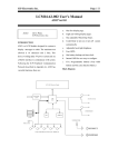
Typical architecture of an Embedded Linux System
Fig. 1.1. Standard Embedded Linux Architecture
4
1. Hardware
Linux normally requires at least a 32-bit CPU containing a memory management unit
(MMU).A sufficient amount of RAM must be available to accommodate the system.
Minimal I/O capabilities are required if any development is to be carried out on the
target with reasonable debugging facilities. The kernel must be able to load a root
filesystem through some form of permanent storage, or access it over a network.
2. Linux Kernel
Immediately above the hardware sits the kernel, the core component of the operating
system. Its purpose is to manage the hardware in a coherent manner while providing
familiar high-level abstractions to user-level software. It is expected that applications
using the APIs provided by a kernel will be portable among the various architectures
supported by this kernel with little or no changes. The low-level interfaces are specific
to the hardware configuration on which the kernel runs and provide for the direct
control of hardware resources using a hardware-independent API. Higher-level
components provide the abstractions common to all UNIX systems, including
processes, files, sockets, and signals. Since the low-level APIs provided by the kernel
are common among different architectures, the code implementing the higher-level
abstractions is almost constant, regardless of the underlying architecture. Between
these two levels of abstraction, the kernel sometimes needs what could be called
interpretation components to understand and interact with structured data coming
from or going to certain devices. Filesystem types and networking protocols are prime
examples of sources of structured data the kernel needs to understand and interact
with in order to provide access to data going to and coming from these sources.
3. Applications and Libraries
Applications do not directly operate above the kernel, but rely on libraries and special
system daemons to provide familiar APIs and abstract services that interact with the
kernel on the application’s behalf to obtain the desired functionality. The main library
used by most Linux applications is the GNU C library, glibc. For Embedded Linux
systems, substitutes to this library that are much less in size than glibc are
preferred.[2]
5
This basic introduction will help in understanding the remainder of the report. The report
begins with the details of installation steps of uClinux OS. It further outlines how to use
Skyeye as a simulator for running operating systems, mimicking the behaviour of a target
board. It then describes the features and configuration of the ARM target board, followed by
the explanation of the process of installing Embedded Linux and developing an application
on it. Once the embedded system setup is ready, the report points towards the development of
a software model of an Inverted Pendulum that needs to be controlled in real-time by the
ARM-Embedded Linux system. Finally the report details a comparison of the results of
performance of the system under various conditions, during the execution of the project.
6
2. LITERATURE SURVEY
With embedded systems fast expanding its reach, subject matter related to this field is
available in abundance. While working on this project we have studied matter from various
sources such as books, online articles and reference manuals. The knowledge gained from
this activity has been of great help to us in understanding the basic concepts related to our
project and has ignited further interest in this topic.
“Linux for Embedded and Real time Applications”, by Doug Abbott has been of great help in
providing an introduction to the process of building embedded systems in Linux. It has
helped us understand the process of configuring and building the Linux kernel and installing
toolchains.
We understood the preponderance of the ARM processors in the field of embedded systems
and the features of ARM processors from the document “The ARM Architecture” by Leonid
Ryzhyk. The ARM architecture is a confluence of many useful features that makes it better
than other peer processors. Being small in size and requiring less power, they prove useful in
providing an efficient performance in embedded applications.
Linux development tools, being available through the GPL license, are available online from
sources such as FTP servers, mailing lists and discussion portals. These online helpdesks
have been the source for all the toolchains that we have downloaded and the subsequent
development.
Modeling of a system is an integral part of any embedded control system development. The
documentation provided by Atmel and Code Vision -AVR helped us to develop a
mathematical model of an Inverted Pendulum on an Atmega 8-bit controller. The aim of the
application is to control this pendulum using a Proportional plus Derivative (PD) controller
which was implemented on ARM-Embedded Linux System. The theory of controllers from
“Mechatronics” by W.Bolton helped us to develop the controlling algorithm.
7
To test the real-time performance of the system, it was subjected to varying process-loads
through the implementation of the “thttpd” web server. The thttpd source and documentation
at ‘www.acme.com’ have enabled us to implement this web server on our system.
POSIX compliant systems always have a detailed documentation that helps in accessing the
hardware with fewer restraints. The “Serial Programming Guide for POSIX Operating
Systems” by Michael R. Sweet is an excellent guide to using serial ports of POSIX compliant
systems. It has helped us in developing an interface between the ARM board and
microcontroller model. The implications of this control system are vast and brings into effect
an intelligent and user friendly control system which is easily reconfigurable.
8
3. UCLINUX
uClinux stands for Microcontroller(uC)-Linux. It is a popular embedded system OS used
traditionally for deeply embedded applications.
3.1 Features of uClinux
The following points detail the characteristic features of uClinux and how they make it
different from the standard desktop Linux OS:
1. The defining and most prevalent difference between the uClinux operating system and
other Linux systems is the lack of memory management. Under Linux, memory
management is achieved through the use of Virtual Memory (VM). uClinux was created
for systems that do not support VM. Since VM is implemented using a processing unit
called Memory Management Unit (MMU), uClinux is usually preferred for ‘MMU-less’
processors.
2. With VM, all processes run at the same address, although a virtual one, and the MMU
takes care of what physical memory is mapped to these locations( by the paging or
segmentation mechanism). So even though the process sees the virtual memory as
contiguous, the physical memory it occupies can be scattered around. Because arbitrarily
located memory can be mapped to anywhere in the process' address space, it is possible to
add memory to an already running process. Without VM, each process must be located at
a place in memory where it can be run. In the simplest case, this area of memory must be
contiguous. Generally, it cannot be expanded as there may be other processes above and
below it. This means that a process in uClinux cannot increase the size of its available
memory at runtime as a traditional Linux process would.
3. The effect of the absence of VM concept is that no memory protection of any kind is
offered. So it is possible for any application or the kernel to corrupt any part of the system
because the user applications and the kernel share the same memory area. The corruption
causes the system to crash, and tracking down random inter-process corruption can be
extremely difficult.
4. Without VM, swap is effectively impossible, but this limitation is rarely an issue on the
kinds of systems that run uClinux. Embedded Systems applications often do not require
9
hard drives or large external memory. Hence uClinux is the ideal option for these
applications.
5. uClinux is only slightly different from Linux with respect to its kernel. Due to absence of
VM, ‘tmpfs’(temporary file system) does not work on uClinux. The uClinux kernel is
highly stripped, modular and totally customizable as per the user requirements.
6. All of the standard executable formats are not supported on uClinux because they make
use of VM features such as stacks and segments. However, uClinux works on the ‘flat’
memory format. It is a condensed executable format that stores only executable code and
data in the same space as the kernel and the file system, along with the relocations needed
to load the executable into any location in memory. The “elf2flt” (Executable Linux
Format to Flat Format) is a tool used to make the applications compatible with uClinux.[3]
7. The implementation of Memory Map (mmap) within the kernel is also very different.
Though it is transparent to the user, it needs to be understood so that it is not used
inefficiently on uClinux systems. The only filesystem that currently guarantees that files
are stored contiguously (i.e. flat memory model) is ‘romfs’. Secondly, only read-only
mappings can be shared, which means a mapping must be read-only in order to avoid the
allocation of memory. The kernel also must consider the filesystem to be “in ROM”,
which means a nominally read-only area within the CPU's address space. This is possible
if the filesystem is present somewhere in RAM or ROM, both of which are addressable
directly by the CPU. Also, when developing the uClinux OS customized for a target
board, it is essential to know the actual hardware memory map so that each peripheral is
addressed properly.
8. For a uClinux developer, the difference, most likely to cause an application to fail under
uClinux, is the lack of a dynamic stack. On desktop Linux, whenever an application tries
to write off the top of the stack some more memory is mapped in at the top of the stack to
allow the stack to grow. Under uClinux, no such facility is available as the stack must be
allocated at compile time only. By default, the uClinux toolchains allocate 4KB for the
stack, which is too small as compared to desktop OS. The second major difference is the
lack of a dynamic heap, which is the area used to allocate memory allocations with
malloc() and other related functions in C. Hence complete information about the memory
map and efficient use of available memory is required while programming.[4]
9. Another difference between standard Linux and uClinux is the lack of the fork() system
call. This can require quite a lot of work on the developer's part when porting applications
that use fork(). The option under uClinux is to use vfork(). vfork() shares many properties
10
with fork(). These system calls, allow a process to split into two processes, a parent and a
child. A process can split many times to create multiple children. When a process calls
fork(), the child is a duplicate of the parent in all ways, but it shares nothing with the
parent and can operate independently, as can the parent. With vfork() this is not the case.
First, the parent is suspended and cannot continue executing until the child exits. The
child, directly after returning from vfork(), is running on the parent's stack and is using
the parent's memory and data. This means the child can corrupt the data structures or the
stack in the parent, resulting in failure. This is avoided by ensuring that the child never
returns from the current stack frame once vfork() has been called and that it calls _exit()
when finishing. The child also must avoid changing any information in global data
structures or variables.[3]
3.2 Skyeye Simulator
Skyeye is an Open Source Software Project (GPL Licence) that has originated from
GDB/Armulator. The goal of Skyeye is to provide an integrated simulation environment in
Linux. Skyeye is a simulation tool that is used to mimic the behavior of the embedded
platform on the standard desktop Linux. It is extremely useful as it enables the developer to
analyse the behaviour of the system before actually implementing it on the hardware. Latest
developments in China have made Skyeye support the ARM architecture-based
microprocessors and Blackfin DSP Processors. By using Skyeye, it is possible to run
Embedded Operating Systems such as ARM Linux, uCos-ii etc. and analyse or debug them at
source level.[5]
11
3.3 Host Specifications
Throughout this report, the user is assumed to be root and the host machine has atleast one
serial port.
The host machine has the following specifications:
1. Operating System: Fedora-Core 9
[root@localhost ~]# uname -r
2.6.25-14.fc9.x86_64
2.Processor Specifications
[root@localhost ~]# cat /proc/cpuinfo
processor
:0
vendor_id
: GenuineIntel
cpu family
: 15
model
:4
model name
: Intel(R) Pentium(R) D CPU 2.80GHz
stepping
:7
cpu MHz
: 2792.995
cache size
: 1024 KB
physical id
:0
siblings
:2
core id
:0
cpu cores
:2
fpu
: yes
fpu_exception : yes
cpuid level
:5
wp
: yes
flags
: fpu vme de pse tsc msr pae mce cx8 apic sep mtrr pge mca cmov pat pse36
clflush dts acpi mmx fxsr sse sse2 ss ht tm pbe syscall nx lm constant_tsc pebs bts pni
monitor ds_cpl cid cx16 xtpr lahf_lm
bogomips
: 5589.48
12
clflush size
: 64
cache_alignment
: 128
address sizes : 36 bits physical, 48 bits virtual
power management:
processor
:1
vendor_id
: GenuineIntel
cpu family
: 15
model
:4
model name
: Intel(R) Pentium(R) D CPU 2.80GHz
stepping
:7
cpu MHz
: 2792.995
cache size
: 1024 KB
physical id
:0
siblings
:2
core id
:1
cpu cores
:2
fpu
: yes
fpu_exception : yes
cpuid level
:5
wp
: yes
flags
: fpu vme de pse tsc msr pae mce cx8 apic sep mtrr pge mca cmov pat pse36
clflush dts acpi mmx fxsr sse sse2 ss ht tm pbe syscall nx lm constant_tsc pebs bts pni
monitor ds_cpl cid cx16 xtpr lahf_lm
bogomips
: 5585.87
clflush size
: 64
cache_alignment
: 128
address sizes : 36 bits physical, 48 bits virtual
power management:
3. The network configuration of the host machine is
[root@localhost ~]# ifconfig
eth0
Link encap:Ethernet HWaddr 00:14:85:9C:6E:62
inet addr:192.168.1.217 Bcast:192.168.1.255 Mask:255.255.255.0
inet6 addr: fe80::214:85ff:fe9c:6e62/64 Scope:Link
13
UP BROADCAST RUNNING MULTICAST MTU:1500 Metric:1
RX packets:1311808 errors:0 dropped:0 overruns:0 frame:0
TX packets:1070 errors:0 dropped:0 overruns:0 carrier:0
collisions:0 txqueuelen:1000
RX bytes:89497811 (85.3 MiB) TX bytes:221766 (216.5 KiB)
Interrupt:21
lo
Link encap:Local Loopback
inet addr:127.0.0.1 Mask:255.0.0.0
inet6 addr: ::1/128 Scope:Host
UP LOOPBACK RUNNING MTU:16436 Metric:1
RX packets:3344 errors:0 dropped:0 overruns:0 frame:0
TX packets:3344 errors:0 dropped:0 overruns:0 carrier:0
collisions:0 txqueuelen:0
RX bytes:171307 (167.2 KiB) TX bytes:171307 (167.2 KiB)
virbr0 Link encap:Ethernet HWaddr 72:29:C6:B0:6D:16
inet addr:192.168.122.1 Bcast:192.168.122.255 Mask:255.255.255.0
inet6 addr: fe80::7029:c6ff:feb0:6d16/64 Scope:Link
UP BROADCAST RUNNING MULTICAST MTU:1500 Metric:1
RX packets:0 errors:0 dropped:0 overruns:0 frame:0
TX packets:29 errors:0 dropped:0 overruns:0 carrier:0
collisions:0 txqueuelen:0
RX bytes:0 (0.0 b) TX bytes:5166 (5.0 KiB)
14
3.4 Installing uClinux on the host Linux platform
Since the ARM board has memory constraints, we compile uClinux on a host platform. The
host processor is primarily Pentium, AMD,etc. hence we need a cross-compiler on the host
machine for making the compiled uClinux assemble on ARM machine language. The basic
requirements include:
1. arm-elf toolchain
2. arm-linux toolchain
3. A hardware simulator (Skyeye)
3.4.1 “arm-elf” toolchain
arm-elf toolchain is used for compiling the linux 2.4(and below ) kernels For instance, armelf-gcc is a c-compiler for arm processor which generates a binary in executable linux
format(elf),similarly,arm-elf-elf2flt converts elf to flat memory format(flt).
We install the arm-elf toolchain as follows:
1. copy arm-elf-tools-20040427.sh in /root/uClinux directory
2. cd /root/uClinux
3. sh arm-elf-tools-20030314.sh [6]
3.4.2 “arm-linux” toolchain
Since it is not recommended to compile the arm linux toolchain source on the host machine,
precompiled
tool
chain
for
arm-linux
can
be
obtained
online
from
here:
http://www.snapgear.org/snapgear/downloads.html
download the following file
http://ftp.snapgear.org/pub/snapgear/tools/arm-linux/arm-linux-tools-20061213.tar.gz
The arm-linux tool chain is used for compiling the linux 2.6.x kernels.
The steps for installation are briefly as follows:
1. Extract the tool chain into the /usr/local/ directory. You must get the /usr/local/armlinux/bin containing all the pre-compiled binary files.
2. /usr/local/arm-linux/bin is then appended to the PATH variable as :
#PATH=$PATH:/usr/local/arm-linux/bin
#export PATH [7]
15
3.4.3 Skyeye simulator
The procedure to install skyeye is as follows
1. copy skyeye_1_2_2_Rel.tar.bz2 in /root/uclinux directory
2. untar skyeye_1_2_2_Rel.tar.bz2 in /root/uclinux/ directory
3. cd /root/uclinux/skyeye_1_2_2_Rel
4. make
5. Add skyeye to PATH as
#export PATH = $PATH:/root/uclinux/skyeye_1_2_2_Rel/binary [5]
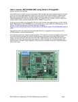
3.4.4 uClinux_Distribution (uClinux-dist-20070130)
The procedure to install uClinux distribution is as follows:
1. untar uClinux-dist-20070130.tar.gz in /root/uclinux directory
2. cd /root/uclinux/uClinux-dist
3. make menuconfig or make xconfig
Fig. 3.1. Screenshot showing the menuconfig window
16
4. Select vendor/product(here select GDB-armulator)
Fig. 3.2. Screenshot for vendor/product selection
5. Select kernel and library version(2.6.x and uClibc)
Fig. 3.3. Screenshot of selection of kernel and library version
6. optionally select application (explained in detail later)
7. save and exit
8. for linux 2.4.x
make dep
9. make
17
Fig. 3.4. Screenshot of completion of make step
Once the kernal images are made, the images are stored in uClinux-dist/images directory
copy the skyeye.conf file to images and edit ./romfs.img to ./boot.rom
cpu: arm7tdmi
mach: at91
mem_bank: map=M, type=RW, addr=0x00000000, size=0x00004000
mem_bank: map=M, type=RW, addr=0x01000000, size=0x00400000
mem_bank: map=M, type=R, addr=0x01400000, size=0x00400000, file=./boot.rom
mem_bank: map=M, type=RW, addr=0x02000000, size=0x00400000
mem_bank: map=M, type=RW, addr=0x02400000, size=0x00008000
mem_bank: map=M, type=RW, addr=0x04000000, size=0x00400000
mem_bank: map=I, type=RW, addr=0xf0000000, size=0x10000000
net: type=rtl8019, mac=0:4:3:2:1:f, ethmod=tuntap, hostip=10.0.0.1
#net: type=rtl8019_16, ethmod=tuntap, hostip=10.0.0.1
#dbct: state=on
10. execute the file as
#cd images
#skyeye -e linux [8]
18
Fig. 3.5. Screenshot of the Skyeye simulator
3.3.5 Running a Sample Program on uClinux
The following are the steps to be taken to run a program on uClinux:
1. Create a folder named "sample" under the uClinux-dist/user directory.
2. Open the Makefile document under the uClinux-dist/user directory using VI or GEdit.
3. Add the following line between the folder list and save the changes.
dir_$(CONFIG_USER_SAMPLE_SAMPLE)
+= sample
4. Now open the "config.in" under "uClinux-dist/config" directory
After the line " mainmenu_option next_comment comment 'Miscellaneous Applications'",
add
bool 'Sample program'
CONFIG_USER_SAMPLE_SAMPLE
Save the changes.
5. After doing the above changes, execute "make menuconfig"
6. A new window opens that has the following option in the menu: Kernel/Library/
Defaults Selection --->
Select the option by pressing Enter key. Now select the "Customise Vendor/User settings"
19
under the new menu that occurs. This selection is done by pressing the Spacebar key. "[*]"
sign indicates that the option is selected. Save and exit the menu.
Fig. 3.6. Screenshot of Kernel and Library selections
Then a new window named "Main Menu" appears. Select "Miscellaneous Applications"
under this menu.
Select "Sample program" under the menu that appears. Then save and exit the menu.
Fig 3.7. Screenshot of Miscellaneous Applications window
7. Execute "make dep"
8. Now create a new document named "Makefile" using Gedit or VI, under the uClinuxdist/user/sample directory. Write the following script into the file:
20
EXEC = sample
OBJS = sample.o
CFLAGS += -I.
all: $(EXEC)
$(EXEC): $(OBJS)
$(CC) $(LDFLAGS) -o $@ $(OBJS) $(LDLIBS)
romfs:
$(ROMFSINST) /bin/$(EXEC)
clean:
-rm -f $(EXEC) *.elf *.gdb *.o
9. Now under the uClinux-dist/user/sample directory write a C program named "sample.c"
10. Execute the "make all" command in the uClinux-dist/ directory. This should result in an
object file "sample" in the uClinux-dist/romfs/bin/ directory.
11. Copy the "linux" image created in uClinux-dist/linux-2.4.x/ directory to the uClinuxdist/images dirctory. Note that this "images" directory should contain 3 files for proper
operation of the program: skyeye.conf boot.rom linux
12. Now execute the command "skyeye -e linux" in the uClinux-dist/images directory. You
will get the Sash (>)command prompt. You can see if "sample" exists in the /bin directory.
13. The program is executed by typing "sample" at the command prompt. [5][8]
Fig 3.8. Screenshot of the simulation of the sample program
21
4. ARM ARCHITECTURE: AN OVERVIEW
4.1 Introduction
ARM is a 32-bit RISC processor architecture developed by the ARM corporation. ARM
processors possess a unique combination of features that makes ARM the most popular
embedded architecture today. First, ARM cores are very simple compared to most other
general-purpose processors, which means that they can be manufactured using a
comparatively small number of transistors, leaving plenty of space on the chip for applicationspecific macrocells. A typical ARM chip can contain several peripheral controllers, a digital
signal processor, and some amount of on-chip memory, along with an ARM core. Second,
both ARM ISA and pipeline design are aimed at minimising energy consumption — a critical
requirement in mobile embedded systems. Third, the ARM architecture is highly modular: the
only mandatory component of an ARM processor is the integer pipeline; all other components,
including caches, MMU, floating point and other co-processors are optional, which gives a lot
of flexibility in building application-specific ARM-based processors. Finally, while being
small and low-power, ARM processors provide high performance for embedded applications.
For example, the PXA255 XScale processor running at 400MHz provides performance
comparable to Pentium 2 at 300MHz, while using fifty times less energy.
4.2 ARM vs RISC
In most respects, ARM is a RISC architecture. Like all RISC architectures, the ARM ISA is a
load-store one, that is, instructions that process data operate only on registers and are separate
from instructions that access memory. All ARM instructions are 32-bit long and most of them
have a regular three-operand encoding. Finally, the ARM architecture features a large register
file with 16 general-purpose registers. All of the above features facilitate pipelining of the
ARM architecture. However, the ARM architecture deviated from the RISC architecture in
some respects to improve its performance. The ARM did not include register windows that
were used by original RISC architectures to reduce complexity. The ARM architecture
introduced an auto-indexing addressing mode, where the value of an index register is
incremented or decremented while a load or store is in progress. ARM supports multipleregister-transfer instructions that allow to load or store up to 16 registers at once.
22
4.3 Thumb instruction set extension
The Thumb instruction set was introduced in the fourth version of the ARM architecture in
order to achieve higher code density for embedded applications. Thumb provides a subset of
the most commonly used 32-bit ARM instructions which have been compressed into 16-bit
wide opcodes. On execution, these 16-bit instructions can be either decompressed to full 32bit ARM instructions or executed directly using a dedicated Thumb decoding unit. Although
Thumb code uses 40% more instructions than equivalent 32-bit ARM code, it typically
requires 30% less space. Thumb code is 40% slower than ARM code; therefore Thumb is
usually used only in non-performance-critical routines in order to reduce memory and power
consumption of the system.
4.4 Pipeline Design in ARM
Fig. 4.1.Pipeline architecture in ARM7 and ARM9 cores
23
4.4.1 The 3-stage pipeline
It is a classical fetch-decode-execute pipeline, which, in the absence of pipeline hazards and
memory accesses, completes one instruction per cycle. The first pipeline stage reads an
instruction from memory and increments the value of the instruction address register, which
stores the value of the next instruction to be fetched. This value is also stored in the PC
register. The next stage decodes the instruction and prepares control signals required to
execute it on. The third stage does all the actual work: it reads operands from the register file,
performs ALU operations, reads or writes memory, if necessary, and finally writes back
modified register values. In case the instruction being executed is a data processing
instruction, the result generated by the ALU is written directly to the register file and the
execution stage completes in one cycle. If it is a load or store instruction, the memory address
computed by the ALU is placed on the address bus and the actual memory access is
performed during the second cycle of the execute stage. This pipeline remained unchanged
from the first ARM processor to the ARM7TDMI core.
4.4.2 The 5 stage pipeline
The 3-stage pipeline has the problem of pipeline stall when a memory read or write operation
is going on, and the next instruction is to be fetched. The solution to this problem was to use
a separate instruction and data cache. First, to make the pipeline more balanced, ARM9TDMI
moved the register read step to the decode stage, since instruction decode stage was much
shorter than the execute stage. Second, the execute stage was split into 3 stages. The first
stage performs arithmetic computations, the second stage performs memory accesses (this
stage remains idle when executing data processing instructions) and the third stage writes the
results back to the register file. This results in a much better balanced pipeline, which can run
at faster clock rate, but there is one new complication — the need to forward data among
pipeline stages to resolve data dependencies between stages without stalling the pipeline.
The ARM10 and ARM11 came up with the 6-stage and the 8-stage pipeline.[9]
24
5. THE ARM TARGET BOARD
5.1 Specifications
The ARM target board is a SMDK2410-MERITECH ARM9 board. The following are its
specifications:
5.1.1 Hardware Specifications
•
MCU(Micro Control Unit)
-
•
•
CPU
-
ARM920T
-
5-Stage pipeline design
-
16 KByte Instruction cache
-
16 KByte Data cache
Operating speed
-
•
•
•
Samsung S3C2410A
230MHZ(Nominal frequency of 200MHz; maximum 266MHz)
RAM Memory
-
64MByte PC133 SDRAM
-
32bit Bus Width
-
Bus frequency 100MHZ
FLASH Memory
-
Nand Flash
-
Small Page (512B/Page)
-
64MByte
Other hardware interface
-
10M Ethernet interface
-
Bus expansion / IDE interface
25
-
16bit data bus
-
4bit address bus
-
2 chip select signals
-
External Interrupt
-
Read and write signals
-
Reset signal
-
GPIO expansion port
-
SPI
-
IIC
-
4-channel ADC
-
3 external interrupt signal
-
LCD expansion interfaces, 24bit true color, with touch-screen interface
-
SD card interface
-
RS232 serial port
-
USB HOST interface (USB1.1)
-
USB DEVICE Interface (USB1.1)
-
Stereo audio output interface
-
Microphone interface
-
JTAG standard 20PIN interface (2.54mm pitch)
-
5V Power Supply
5.1.2 Software Specifications
-
Linux Kernel 2.4
-
VIVI Bootloader
-
YAFFS File System
-
JFlash for programming bootloader in PC side
-
SJF Downloader
26
5.2 Installation Steps
5.2.1 Installing the vivi bootloader using JTAG
SEC JTAG FLASH (SJF) can program SMDK2410 flash memory (K9S1208,E28F128)
through JTAG port and read/write data from/to a specified address. For this purpose we need
to install GIVEIO.SYS file. Only for this operation a host running Windows OS is used.
5.2.1.1 Installing GIVEIO.SYS
In windows NT/2000/XP, an application cannot access any I/O such as the parallel port. So,
GIVEIO.SYS enables SJF.exe to access the parallel port without any memory fault. In
windows 95/98, GIVEIO.SYS is not needed.
For Windows 2000/XP, use the following procedure:
1. Login as administrator
2. Copy the giveio.sys file to systemroot\system32\drivers.
3. Choose Control Panel, and choose Add/Remove Hardware.
4. Select 'Add/Troubleshoot a device'
5. Select 'Add a new device' and choose Next, and select 'No, I want to select the
hardware from a list'.
6. Select ‘Other devices’ and choose 'Have Disk...'.
7. Choose 'Browse...' locate the folder where giveio.inf file is present.
8. Complete the remaining process.
27
5.2.1.2 To program the K9S1208 NAND Flash with the Bootloader code
1. Prepare your own boot loader image.(For example, 2410loader.bin is used here)
2. Open the 'CD \ Software \ ' directory, double-click the 'DownloadVivi_Vga.bat' batch
file, you will get a command window, as shown below:
Fig. 5.1. Screenshot of bootloader download to NAND Flash
5.2.2 Installation of kernel and filesystem using TFTP server
To download images of kernel and file systems from the host machine to the target board a
network interface is setup using a TFTP server at the host end.
5.2.2.1 Configuring a TFTP server on the host
1. Download and install a TFTP server using the command
<root@localhost~># yum install tftpd-server
2. Create a directory ‘tftpboot’ in the ‘/’ directory
3. Place the zImage and the image of the root file system in the ‘tftpboot’ folder. This is
because the TFTP server will let the target access files that are present only in the
‘tftpboot’.
4. Start the TFTP server by using the following commands
<root@localhost~>#iptables -F
<root@localhost~>#service xinetd start
28
‘iptables -F’ command flushes the current firewall settings and allows all the IP
addresses to use the TFTP service on the host machine.
(Note: For doing the above operations you must be the root user.)
Now the host is ready to transfer the images to the target board. The next step is the
installation of Linux. Linux installation is divided into three steps:
1. Flash memory partition and format (usually a Nand Flash).
2. Download the Linux kernel.
3. Download the file system.
5.2.2.2 Partition and format Flash memory
The flash memory can be partitioned using the following steps:
1. Hold down the spacebar while starting up the target board in Minicom,
to see vivi> command line.
2. Enter the command
bon part 0 192k 2m
bon is the partition command, this means that the Nand Flash is divided into three
zones:
0 ~ 192k: size of 192k
192k ~ 2M: size 1.8Mbyte
2M ~ flash terminal
Please Note: After partition and format, please do not turn off the target board's
power supply, Otherwise, we need to re-use of JTAG line to download VIVI, This is
because the target of the on-board flash memory is now being cleared.
29
5.2.2.3 Download the Kernel and File System Images
Before downloading the kernel image and file system we must first ensure proper network
settings.
1. As we enter to command line vivi. Type the command
net
Fig. 5.2 Running ’net’ command on the vivi command line
At this time, we can see the network settings.
2. The IP address must be set up and the TFTP server should be started (Refer to section
5.2.2.1).
3. In vivi command line, run the command
net set ipaddr 192.168.1.241
Then use the ‘net’ command to view status, we can see that the target board's IP
address is changed.
4. At this time we run the ‘net save’ command to save the settings.
5. Our next step is to download a kernel image. Run the following command from the
host
net tftp 192.168.1.156 0x30008000 zImage
At this time the ‘zImage’ has been downloaded from the computer to the SDRAM of
the target board.
6. To write it to the Flash partition. Run the command
net flash kernel
Here, kernel refers to the kernel partition.
30
7. To download the file system to the flash use the following commands
net tftp 192.168.1.156 0x30008000 root_1.yaffs
net flash root
Restart the target board, to boot into Embedded Linux.[10]
Here are the steps for installing the Embedded Linux on target board from host PC
having Fedora Linux 09 as operating system.
5.2.3 Building Linux image on the host
5.2.3.1 Installing cross-compiler toolchain
1. Create a directory /usr/local/arm
2. Change the directory to /usr/local/arm
3. Untar the cross_2.95.3.tar.bz2 file downloaded from www.handhelds.org
in this directory.
4. Type this command to export path
$export PATH=$PATH:/usr/local/arm/2.95.3/bin
5.2.3.2 Compiling Linux source
1. Untar the file 2410Linuxsrc.tar.gz from the CD. This will generate a directory
named 'linux'.
2. Change directory to linux by command cd
We can type the command '$ make menuconfig' if desired, for customizing
3. Type the following command to make dependencies.
$ make dep
4. $ make zImage
This will create the image in './arch/arm/boot/' directory.[2]
31
6. OVERVIEW OF THE PROJECT
It is evident that uClinux and Embedded Linux can work as a reliably on time system. The
project now aims to explore the possibilities of an ARM processor S3C2410 using Embedded
Linux for a real time control application. The problem statement chosen is to control an
Inverted Pendulum.
Since development of a mechanical inverted pendulum is tedious and most industry
development processes recommend the use of a mathematical model for simulating the
hardware, we have chosen to model the Inverted Pendulum on an 8-bit microcontroller
Atmega8535.This model helps in saving development time and also gives comparable results
which can be used to evaluate the real time control system.
A Proportional plus Derivative (PD) control system is implemented as an application on the
ARM-Embedded linux and communication is established between the ARM board and the
model using serial communication. By doing this one can determine how well the ARM
processor will implement the control system. Data such as force, angle, etc. are also logged
into the database which could be used for plotting and analysis.
Since a single user process is being run on the Embedded ARM Linux, one cannot evaluate
the critical conditions for the control system in which it would fail to control. The project
accomplishes this task by running a thttpd web server in parallel with the PD control
application. Various features such as remote control are also introduced for ease of use.The
process-load on Embedded Linux is increased by using multiple clients which access the web
page that is hosted on the ARM processor.
The database results are now compared and statistics are evaluated between Desktop and
Embedded Linux. It is expected that the ARM processor which runs Embedded Linux will
show superior results.
32
7. MODEL OF AN INVERTED PENDULUM
The inverted pendulum is a classic problem in dynamics and control theory and widely used
as a benchmark for testing control algorithms (PID controllers, neural networks, fuzzy
control, genetic algorithms, etc). This concept is best implemented in the technology of
‘Segway’, a self-balancing transportation device. The largest implementation of the inverted
pendulum is on huge lifting cranes in shipyards. When moving the shipping containers back
and forth, the cranes move the box accordingly so that it never swings or sways. It always
stays perfectly positioned under the operator even when moving or stopping quickly.[11]
7.1 Working
Fig. 7.1. Schematic for Inverted Pendulum
An inverted pendulum is a physical device consisting of a cylindrical bar free to oscillate
around a fixed pivot. The pivot is mounted on a carriage/cart, which in turn can move in the
horizontal direction. The cart is driven by a motor, which can exert on it a variable force,
depending on the dynamics of the pendulum. The bar would tend to fall down from the top
vertical position, which is a position of unstable equilibrium. The goal of the inverted
pendulum
controller
is
to
stabilize
the
bar
in
the
top
vertical
position.
This is possible by exerting on the carriage, a force which tends to contrast the 'free'
pendulum dynamics. The correct force has to be calculated measuring the instant values of
the horizontal position and the pendulum angle. The system (pendulum + cart + motor) can
be modelled as a linear system if all the parameters are known, in order to find a controller to
stabilize it. If all the parameters are not known, we try to 'reconstruct' the system parameters
33
using
measured
data
on
the
dynamics
of
the
pendulum.[12]
7.2 Approximate Model of the Inverted Pendulum
For developing the approximate mathematical model of the inverted pendulum, it is
necessary to mimic the mechanics of the free-falling rod. This is done through the dynamic
analysis of the Free Body Diagram of the system. For our mathematical model, the following
are the principle assumptions with respect to the entire system:
-
Length of rod: L=2mts
-
Entire mass of the rod is assumed to be concentrated at its centre of mass (i.e. at
half of its length). Centre of mass h=1mt
-
Centre of mass of the cart and motor are at ground level
-
Contributing mass of the rod, cart and motor m=1kg
Fig. 7.2. Free Body Diagram
Consider a pendulum, falling freely under gravity, about the pivot as shown in the diagram
alongside. At an instant of time t it is at a displacement of angle θ from its mean position (0
degrees), with a linear velocity of v. In the next time interval dt it displaces by angle dθ; such
that the change in the force due to gravity remains constant i.e. sin(θ) is approximately equal
to sin(θ+dθ).
Applying fundamental law of mechanics to the rod.
d θ= ω*(dt) + (1/2)*α*(dt)2 ……(1)
By applying law of Conservation of Energy between initial position A (θ=0) and current
position B (θ=θ)
P.E.a = P.E.b +K.E.b
mgh = mghcos(θ) +(1/2)mv2
34
v = √[2gh(1-cosθ)]
since v= r ω,
where v=linear velocity, r=radius of circular motion, ω=angular velocity
ω=√[2gh(1-cosθ)]/(h)
ω = (h)* √[2gh(1-cosθ)] ……… (2)
By considering rotational motion of the rod about the pivot,
Γ= I α
Where Γ = Torque = mgh sin(θ) – Fhcos(θ)
I = Moment of Inertia about pivot = mL2 /3
α = Angular acceleration
α = (3/4L) ( g sin(θ) – (F/m)cos(θ) ) ……(3) [13]
put equations (2) and (3) in (1) , the discrete mathematical model is :
dθ = (h)* √[2gh(1-cosθ)] * (dt) + (1/2)* (3/4L) ( g sin(θ) – (F/m)cos(θ) )*(dt)2
7.3 Communication protocol between the model and the controller
−
The model first checks if the pendulum is initially fallen or not by examining the fail
flag, as long as it is found 0 the steps 2 to 6 are executed sequentially.
−
Controller sends character ‘A’ to indicate it is ready to send Force values to the
model, or it sends character ‘Z’ to (re)initialize the pendulum to original position.
−
On receipt of either ‘A’ or ‘Z’ the model sends character ‘B’ as an acknowledgement
and becomes ready to receive the Fore from the Controller
35
−
The controller sends the 4 digit force, character by character, preceded by the
character ‘+’ or ‘ –’ to indicate the sign of the force
−
The model then sends the current value of θ and dθ to the controller character by
character preceded by character ‘0’ for positive and ‘1’ for negative.
−
Model then calculates the values of dθ and θ as per the derived mechanical equation
−
If θ becomes +90 (i.e 090) or -90 (i.e 190) then the model sends a character ‘F’ to the
controller to indicate the controller has failed and that the pendulum has fallen. Now
the flag for fail is set to 1.
36
ISR STARTS
CLEAR INTERRUPTS
A
CONFIRM ‘A’
SCAN FOR
SYNC CHAR
A or Z
CONFIRM ‘Z’ AND
INITIALIZE PENDULUM
REPORT ‘F’, SET INTERRUPTS
AND RETURN TO MAIN
IS FAIL ==1?
SEND ACKNOWLEDGEMENT ‘B’
RECEIVE FORCE IN THE FORM OF 5 CHARACTERS
CONVERT CHAR
FORCE INTO
INT
PRINT CURRENT VALUES OF θ AND dθ IN DEGREES TO THE CONTROLLER
WITH PROPER SIGN AND APPENDEDED ZERO CHARACTERS
COMPUTE THE MATHEMATICAL MODEL
SET INTERRUPTS
AND RETURN
HAS THE
PENDULUM
FALLEN?
A
Fig. 7.3. Flowchart for inverted pendulum model
37
8. PD CONTROLLER APPLICATION ON ARM
The PD controller is a combination of proportional and derivative controller.
8.1 Proportional mode
In this mode a linear relation exists between the controller output and the error signal, when
the error increases the controller output increases and vice versa. In the application, the
deviation of angle from 0 degree is the error. The range of error over 0-100% of controller
output is called proportional band (PB).
The expression for proportional mode output is
p(t)=kp*e(t)+ P0
where kp= proportional gain
p(t)= controller output
e(t)= error input
P0= controller output at the start of the error
Proportional band= 100/kp
The characteristics of Proportional controller are:
1. When error is zero, the controller output is equal to P0 i.e. constant
2. If there is an error, for every 1% of error, a correction of kp% is added or subtracted
from P0 depending on the sign.
3. There is a band of error about zero of magnitude ‘PB’ within which the output is not
saturated at 0% or 100%.
8.2 Derivative mode
For derivative controller, the controller output is
p(t)=kd*d/dt e(t)
where kd=derivative mode gain
Characteristics of Derivative controller
1. If error=0, this mode provides no output.
2. If error=constant, this mode provides no output.
38
3. If error is changing with time, the mode contributes an output of kd% for every
1%/sec rate of change of error.
4. For direct action, a positive rate of change of error produces a positive derivative
mode output.
The derivative mode is used with a small gain because rapid rate of change of error produces
a very large, sudden change in controller output leading to instability. The derivative control
action is also called as rate action or anticipatory action. This derivative action is not used
alone because it produces no output if error is constant.
8.3 PD Mode
PD controller combines the advantages of both proportional and derivative controller. The
expression for PD controller output is
p(t)=kp*e(t)=kd* d/dt e(t)+ P0
The proportional mode of the PD controller produces a permanent residual error about its
operating point of the controlled variable when a change in load occurs. This error is called
offset. It can be minimized by a larger gain kp but larger the gain, the proportional band
decreases. Hence the PD controller cannot eliminate the offset of the proportional controller
but it can handle fast process load changes as long as the offset error is acceptable. [14]
8.4 Controller Algorithm:
The controller algorithm runs on the ARM processor. It is interfaced to the Atmega8535
through a serial port. The model of the inverted pendulum runs on the Atmega board. There is
a fixed protocol followed to enable synchronization between the model and the controller.
The following is the protocol:
1. The controller sends a character ‘Z’ for the first time to the inverted pendulum.
2. In response the pendulum model sends a character ‘B’ to the controller.
3. Now the controller sends the acceleration which it has computed for the pendulum to
return to its equilibrium position. For the first time the acceleration is zero.
39
4. The controller waits for the Atmega to send the current angular displacement (θ) and
the change in the angular displacement (dθ).
5. The controller now calculates the new value of acceleration using the values of θ, dθ,
kp and kd.
6. The controller sends a character ‘A’ to the Atmega board for synchronization.
7. Steps 2 to 6 are repeated for the number of times the code is run.
40
9. SERIAL COMMUNICATION
Computers transfer information (data) in the form of one or more bits at a time. Serial refers
to the transfer of data one bit at a time. Serial communication is used by most network
devices, keyboards, mice, MODEMs and terminals. When doing serial communications, each
word (i.e. byte or character) of data that is sent or received is sent one bit at a time. Each bit is
either on or off. The terms mark for the on state and space for the off state are generally used.
The speed of the serial data is most often expressed as bits-per-second ("bps") or Baudot rate
("baud"). This just represents the number of ones and zeroes that can be sent in one second.
When referring to serial devices or ports, they are either labelled as Data Communications
Equipment ("DCE") or Data Terminal Equipment ("DTE"). The difference between them is
that every signal pair, like transmit and receive, is swapped. When connecting two DTE or
two DCE interfaces together, a serial null-MODEM cable or adapter is used that swaps the
signal pairs.
9.1 RS-232 Standard
RS-232 is a standard electrical interface for serial communications defined by the Electronic
Industries Association ("EIA"). RS-232 actually comes in 3 different flavours (A, B and C)
with each one defining a different voltage range for the on and off levels. The most
commonly used variety is RS-232C, which defines a mark (on) bit as a voltage between -3V
and -12V and a space (off) bit as a voltage between +3V and +12V. The RS-232C
specification states that these signals can go about 25 feet (8m) before they become unusable.
9.2 Asynchronous Communication
For the computer to understand the serial data coming into it, it needs some way to determine
where one character ends and the next begins. In asynchronous mode the serial data line stays
in the mark (1) state until a character is transmitted. A start bit precedes each character and is
followed immediately by each bit in the character, an optional parity bit, and one or more
stop bits. The start bit is always a space (0) and tells the computer that new serial data is
available. Data can be sent or received at any time, thus the name asynchronous.
41
Fig.9.1. Timing diagram of asynchronous mode
The optional parity bit is a simple sum of the data bits indicating whether or not the data
contains an even or odd number of 1 bits. With even parity, the parity bit is 0 if there is an
even number of 1's in the character. With odd parity, the parity bit is 0 if there is an odd
number of 1's in the data.
The remaining bits are called stop bits. There can be 1, 1.5, or 2 stop bits between characters
and they always have a value of 1. Stop bits traditionally were used to give the computer time
to process the previous character, but now only serve to synchronize the receiving computer
to the incoming characters.
Asynchronous data formats are usually expressed as "8N1", "7E1", and so forth. These stand
for "8 data bits, no parity, 1 stop bit" and "7 data bits, even parity, 1 stop bit" respectively.
9.3 Accessing the Serial Port
Like all devices, UNIX provides access to serial ports via device files. To access a serial port
the corresponding device file has to be opened.
9.3.1 Opening a Serial Port
Each serial port on a UNIX system has one or more device files (files in the /dev directory)
associated with it. Since a serial port is a file, the open() function is used to access it.
The following command is used to open the serial port:
fd = open("/dev/ttyS0", O_RDWR | O_NOCTTY | O_NDELAY);
The device file is opened with two other flags along with the read write mode. OCTTY flag
tells UNIX that this program does not want to be the "controlling terminal" for that port. If
this is not specified then any input (such as keyboard abort signals and so forth) will affect
the process. The O_NDELAY flag tells UNIX that this program does not care what state the
DCD signal line is in - whether the other end of the port is up and running. If this flag is not
specified, the process will be put to sleep until the DCD signal line is the space voltage.
42
9.3.2 Writing Data to the Port
Writing data to the port is done using the write2) system call to send data it:
n = write(fd, "ATZ\r", 4);
if (n < 0)
fputs("write() of 4 bytes failed!\n", stderr);
The write function returns the number of bytes sent or -1 if an error occurred.
9.3.3 Reading Data from the Port
When the port is operated in raw data mode, each read() system call will return the number of
characters that are actually available in the serial input buffers. If no characters are available,
the call will block (wait) until characters come in, an interval timer expires, or an error
occurs. The read function can be made to return immediately by doing the following:
fcntl(fd, F_SETFL, FNDELAY);
The FNDELAY option causes the read function to return 0 if no characters are available on
the port. To restore normal (blocking) behavior, call fcntl() without the FNDELAY option:
fcntl(fd, F_SETFL, 0);
This is also used after opening a serial port with the O_NDELAY option.
9.3.4 Closing a Serial Port
To close the serial port, just use the close system call:
close(fd);
Closing a serial port will also usually set the DTR signal low which causes most MODEMs to
hang up.[15]
43
9.4 Serial Communication in S3C2410
The S3C2410X UART (Universal Asynchronous Receiver and Transmitter) provides three
independent asynchronous serial I/O (SIO) ports, each of which can operate in Interruptbased or DMA-based mode. In other words, the UART can generate an interrupt or a DMA
request to transfer data between CPU and the UART. The UART can support bit rates of up
to 115.2K bps using system clock. If an external device provides the UART with UCLK, then
the UART can operate at higher speed. Each UART channel contains two 16-byte FIFOs for
receive and transmit. The S3C2410X UART includes programmable baud rates, infra-red
(IR) transmit/receive, one or two stop bit insertion, 5-bit, 6-bit, 7-bit or 8-bit data width and
parity checking. UART0 is used to send serial data to the host machine which can be viewed
via minicom. Minicom then displays the boot up sequence, the command prompt of vivi and
shell prompt of embedded linux.
Fig. 9.2. Serial port architecture in S3C2410
44
9.5 Minicom
Minicom is an application which is used to view the contents of the serial port receive buffer
when it acts as a receiver and send data to the transmit buffer when acting as a transmitter.
The following are the steps to start Minicom and edit its settings:
1. [root@localhost root]# minicom -s
This command starts Minicom in Setup mode. One can select the serial port to be
interfaced, baud rate and other settings of the serial port.
2. Press ‘A’ key for setting the ‘Serial Device’, then give the complete path of the serial
port which is connected to target board. (For COM1, write /dev/ttyS0, for COM2,
write /dev/ttyS1.)
Fig. 9.3 Minicom setup screenshot
3. Press ‘E’ key for setting up ‘bps/Par/Bits’. Press ‘I’ to set up ‘bps’ to 115200, Press
‘V’ to set up ‘Data bits’ to 8, Press ‘W’ to set up ‘Stop bits’ to ‘1’, and ‘V’ to set up
‘parity’ to ‘NONE’.
45
Fig. 9.4 Screenshot of Baud rate setting in Minicom
4. Press ‘F’ key for setting up ‘Hardware Flow Control’ to ‘NO’. Press ‘G’ key for
setting up ‘Software Flow Control’ to ‘NO’. The default value is ‘NO’.
5. Once the setup is done, press the ‘Enter’ key. And select ‘Save setup as dfl’ item, then
press ‘Enter’ for saving the values.
6. Press the ‘Exit’ key, to exit from the setting mode. Currently, the set points are stored
to the file ‘/etc/minirc.dfl’.
7. To quit from Minicom, please press ‘Ctrl + A’ and then ‘Z’, at last press ‘Q’ key.
Then Selecting ‘Yes’, the Minicom is quit.[16]
46
10. EMBEDDED WEB SERVER: thttpd
Web servers play an important role in industry. If a system is to be accessed and controlled
remotely, and if the data is to be presented in a user-friendly manner, then it is very important
to have web servers. Embedded systems that are hosting control applications should have
web services enabled so that the status of the system can be checked from a distant place. At
the same time, one can also keep an option of controlling the system remotely, if sufficient
security of control is ensured. Examples of prominent embedded web servers are Boa, thttpd,
mini-thttpd, micro-thttpd. In our project, we have used the thttpd web server.
10.1 Thttpd(Tiny/Turbo/Throttling) HTTP server: An Overview
It is a simple, small, portable, fast, and secure HTTP server. It is not a feature-rich web server
but its features suffice most of the applications and has a very important feature called URLtraffic-based throttling. Some important concepts before starting with thttpd are:
10.1.1 Chroot
‘chroot()’ is a system call that restricts the program's view of the filesystem to the current
directory and directories below it. It becomes impossible for remote users to access any file
outside of the initial directory. The restriction is inherited by child processes, so CGI
programs get it too. This is a very strong security measure, and is recommended. The only
downside is that only root can call chroot(), so this means the program must be started as
root. However, the last thing it does during initialization is to give up root access by
becoming another user, so this is safe. The program can also be compile-time configured to
always do a chroot(), without needing the -r flag.
One has to make sure that any shells, utilities, and config files used by your CGI programs
and scripts are available. If you have CGI disabled, or if you make a policy that all CGI
programs must be written in a compiled language such as C and statically linked, then you
probably don't have to do any setup at all.
47
10.1.2 CGI (Common Gateway Interface)
thttpd supports the CGI 1.1 spec. In order for a CGI program to be run, its name must match
the pattern specified either at compile time or on the command line with the -c flag. This is a
simple shell-style filename pattern. You can use * to match any string not including a slash,
or ** to match any string including slashes, or ? to match any single character. You can also
use multiple such patterns separated by |. The patterns get checked against the filename part
of the incoming URL. One must not forget to quote any wildcard characters to avoid any
misunderstanding by the shell.
Restricting CGI programs to a single directory lets the site administrator review them for
security holes, and is strongly recommended. If there are individual users that you trust, you
can enable their directories too. If no CGI pattern is specified at the compile time or at the
command line, then CGI programs cannot be run.
10.1.3 Throttling
The throttle file lets you set maximum byte rates on URLs or URL groups. You can
optionally set a minimum rate too. The format of the throttle file is very simple. A ‘# ‘starts a
comment, and the rest of the line is ignored. Blank lines are ignored. The rest of the lines
should consist of a pattern, whitespace, and a number. The pattern is a simple shell-style
filename pattern, using ? / ** / *, or multiple such patterns separated by |.
Throttling is implemented by checking each incoming URL filename against all of the
patterns in the throttle file. The server accumulates statistics on how much bandwidth each
pattern has accounted for recently. If a URL matches a pattern that has been exceeding its
specified limit, then the data returned is actually slowed down, with pauses between each
block. If that's not possible (e.g. for CGI programs) or if the bandwidth has gotten way larger
than the limit, then the server returns a special code saying 'try again later'.
The minimum rates are implemented similarly. If too many people are trying to fetch
something at the same time, throttling may slow down each connection so much that it's not
really useable. Furthermore, all those slow connections clog up the server, using up file
handles and connection slots. Setting a minimum rate says that past a certain point you should
48
not even bother - the server returns the 'try again later" code and the connection isn't even
started.
10.1.4 Multihoming
Multihoming means using one machine to serve multiple hostnames. If we want to have
different web addresses (say for different users) all running on the same physical hardware,
then this feature is known as multihoming, also known as “virtual hosting”. There are 3 steps
to set up “virtual hosting”.
1. Make DNS entries for all the hostnames using CNAME aliases according to the
HTTP/1.1 rules.
2. Make separate directories for each web address.
3. Enable the virtual hosting option using –v flag or by using the ALWAYS_VHOST
option in config.h
10.1.5 Symlinks and Permissions
For any request that comes to the server, the path is checked for any symbolic links. If they
exist, then they are expanded to indicate the real path. Then when there are no symbolic links
in the path, it is checked if the path is pointing to a location above the web server directory. If
it is, then an error page is returned.
Thttpd is very particular about the permissions of the files that it serves. For data files, it
requires that these files are “world-readable”. This means that not only root, or a particular
group but any user must be permitted to read the file. It also requires that the “execute” bit be
off for data files. For a CGI program, the execute bit has to be set and it must match the CGI
pattern. In summary, the data files should have a permission pattern of 644(r w - r - - r - -),
directories should have a permission pattern of 755(r w x r – x r – x) and CGI programs
should have 755(r w x r – x r – x)
The configuration of the server can be mentioned either in a configuration file or it can be
specified at the command line in the form of flags. At the command line, the following flags
are available as options:
-C :
Specifies a config-file to read. These options can also be mentioned at the
command line.
49
-p
:
Specifies an alternate port number to listen on. The default is 80. The config-file
option name for this flag is "port", and the corresponding option in the config.h file
is DEFAULT_PORT
-d
:
Specifies a directory to chdir() to at startup. The config-file option name for this
flag is "dir", and the config.h options are.
-r :
Do a chroot() at initialization time, restricting file access to the program's current for
directory. If -r is the compiled-in default, then -nor disables it. The config-file
option names this flag are "chroot" and "nochroot", and the config.h option is
ALWAYS_CHROOT.
-dd
:
Specifies a directory to chdir() to after chrooting. If you're not chrooting, you might
as well do a single chdir() with the -d flag. If you are chrooting, this lets you put the
web files in a subdirectory of the chroot tree, instead of in the top level mixed in
with the chroot files. The config-file option name for this flag is "data_dir".
-nos : Don't do explicit symbolic link checking. Normally, thttpd explicitly expands any
symbolic links in filenames, to check that the resulting path stays within the original
document tree. If you want to turn off this check and save some CPU time, you can
use the -nos flag, however this is not recommended. Note, though, that if you are
using the chroot option, the symlink checking is unnecessary and is turned off, so the
safe way to save those CPU cycles is to use chroot. The config-file option names for
this flag are "symlinkcheck" and "nosymlinkcheck".
-v
: It enables virtual hosting. –nov disables it. The config-file option names for this
flag are "vhost" and "novhost", and the config.h option is ALWAYS_VHOST.
-g : Use a global password file. This means that every file in the entire document tree is
protected by the single .htpasswd file at the top of the tree. Otherwise the semantics of
the .htpasswd file are the same. If this option is set but there is no .htpasswd file in the
top-level directory, then thttpd proceeds as if the option was not set - first looking for a
local .htpasswd file, and if that doesn't exist either then serving the file without any
50
password. If -g is the compiled-in default, then -nog disables it. The config-file option
names for this flag are "globalpasswd" and "noglobalpasswd", and the config.h option
ALWAYS_GLOBAL_PASSWD.
-u : Specifies what user to switch to after initialization when started as root. The default is
"nobody". The config-file option name for this flag is "user", and the config.h option is
DEFAULT_USER.
-c : Specifies a wildcard pattern for CGI programs, for instance "**.cgi" or "/cgi-bin/*".
The config-file option name for this flag is "cgipat", and the config.h option is
CGI_PATTERN.
-t : Specifies a file of throttle settings. The config-file option name for this flag is "throttles".
-h : Specifies a hostname to bind to, for multihoming. The default is to bind to all hostnames
supported on the local machine. The config-file option name for this flag is "host", and
the config.h option is SERVER_NAME.
-l : Specifies a file for logging. If no -l argument is specified, thttpd logs via syslog(). If "-l
/dev/null" is specified, thttpd doesn't log at all. The config-file option name for this flag
is "logfile".
-i : Specifies a file to write the process-id to. If no file is specified, no process-id is written.
You can use this file to send signals to thttpd. The config-file option name for this flag is
"pidfile".
-T : Specifies the character set to use with text MIME types. The default is iso-8859-1. The
config-file option name for this flag is "charset", and the config.h option is
DEFAULT_CHARSET.
-V : Shows the current version info.
-D : This was originally just a debugging flag, however it's worth mentioning because one of
the things it does is prevent thttpd from making itself a background daemon. Instead it
runs in the foreground like a regular program. This is necessary when you want to run
thttpd wrapped in a little shell script that restarts it if it exits.
If using a config-file to set the settings, its syntax is series of “option” or “option=value”
separated by a whitespace in between.[17]
51
10.1.6 Installation steps of Thttpd:
1. Download the latest version of thttpd : thttpd-2.25b.tar.gz from the website
www.acme.com
2. Untar the package graphically or at the command line as: tar –zxvf thttpd-2.25b.tar.gz
3. You get a single folder named thttpd-2.25b. cd to the folder at the command line.
4. Run the command: CC=arm-linux-gcc ./configure
5. Then run the command ‘make’
6. A binary by the name of ‘thttpd’ is generated.
7. Copy the binary to the target board through the USB interface in the /usr/sbin
directory
8. Execute the binary with the appropriate flags at the command line.
./thttpd -p
[Port No.] -d [Document Root] -c [Files that should be executed as
CGI scripts] -u [The user by the name of which the server executes]
Eg. ./thttpd -p 8000 -d /usr/local/www/cgi-bin -c “**” -u root
The flow of the code of web application that we are using in our project is as follows:
The index page offers two options:
1. A hyperlink to start the pendulum and its control. Clicking on the link runs a shell
script that executes the executable file generated from the controller’s C program. The
process begins by sending the character ‘Z’ to the Atmega indicating that it should
reset its software.
2. A hyperlink to check the current status of the pendulum ie. the current inclination, the
current rate of change of inclination and the most recent force that was supplied by
the controller algorithm in the ARM to the model in the Atmega. The controller stores
the values of the force it supplies and the recently received values of theta and d_theta
in a file. When the link is clicked, an executable generated from a C program executes
to read this file and print the values to the browser of the client.
52
11. RESULTS AND ANALYSIS
This section of the report shows the results that we have obtained during the course of the
project. The control system i.e. the ARM-Embedded Linux System and the Inverted
Pendulum model as a whole has been tested under various load conditions. As already
mentioned, the load corresponds to the process-load that builds when the thttpd web server is
started in parallel with the control program and the number of clients goes on increasing.
Simultaneously, we have also tested the control program on Desktop Linux, and documented
the result. The various conditions, for which the program has been tested and for which the
results are provided here, are:
1. Running the code on Desktop Linux, v/s running the code on ARM-Embedded
Linux
2. Running the code on the ARM without starting the web server v/s running the
code on ARM board with server started and 2 clients accessing the webpage
3. Running the code on the ARM without starting the web server v/s running the
code on ARM board with server started and 2 clients accessing the webpage
with 1 client refreshing the status page every 2 sec.
53
Fig. 11.1. Gnuplot of force v/s time for desktop and ARM
Fig. 11.2. Gnuplot of theta v/s time for desktop and ARM
54
Fig. 11.3. Gnuplot of force v/s time for ARM with varying load
Fig. 11.4. Gnuplot of theta v/s time for ARM with varying load
55
Fig. 11.5. Gnuplot of force v/s time for ARM with varying load (with 2 sec refresh)
Fig. 11.6. Gnuplot of theta v/s time for ARM with varying load (with 2 sec refresh)
56
1. Analysis of performance of desktop and ARM processor
The first plot (Fig 11.1) is “Force v/s time” and the second plot (Fig 11.2) is “Angular
displacement v/s time”. The green plot is indicating the ARM performance whereas the red
plot is for the desktop. From the plot it can be inferred that the performance of ARM and the
desktop is comparable, however the controlling algorithm running on the desktop loses
synchronization after a while. However the ARM processor controls the inverted pendulum
for any amount of time. Hence it is preferred over the desktop for real time applications.
2. Analysis of performance of ARM processor with varying loads
Plots 3 (Fig 11.3) and 4 (Fig 11.4) are plotted when there are two clients accessing the
webpage (red plot) and it is compared with no load condition (green plot). It can be observed
that the pendulum settles down to its equilibrium condition quickly as compared to the case
when two clients are present. It can be seen that when there is load on the ARM processor the
overshoot increases and it takes much longer for the pendulum to settle down.
Plots 5 (Fig 11.5)and 6 (Fig 11.6) are plotted when there are two clients accessing the
webpage and one of them is refreshing the page every two seconds (red plot) and it is
compared with no load condition (green plot). Here, it be demonstrated that the settling time
of the pendulum is much higher in case of two clients who are periodically refreshing the web
page.
Thus it can be inferred that though the time required for the pendulum to settle down to its
equilibrium position varies depending on the load conditions, the ARM processor can control
the inverted pendulum successfully.
57
12. CONCLUSION
In light of the result analysis presented earlier we can empirically conclude that the ARM
processor S3C2410 has performed extraordinarily well while running the Real Time Control
Application when compared to Desktop Linux. Desktop Linux underperformed severely by
losing synchronization when the number of control transactions was increased beyond the
count of five hundred. Addition of a web server also made the Desktop Linux a highly
unreliable system. From the previous results, it can be viewed that the ARM Linux controller
performance is satisfactory even when it hosts web pages and services multiple client
requests. Hence it can be concluded that the overhead involved in running an application on
an ARM processor is much less than that on a Desktop Linux, which is why, a Desktop Linux
cannot be a reliable platform for running time critical applications. Therefore the features of
ARM architecture combined with Embedded Linux helps us in building a reliably on time
platform.
58
13. FUTURE SCOPE
The Inverted Pendulum may be used as a benchmark, to test the validity and the performance
of the software underlying the state-space controller algorithm, i.e. the used operating
system. Actually the control algorithm can be implemented from the numerical point of view
as a set of mutually co-operating tasks, which are periodically activated by the kernel, and
which
perform
different
calculations. The
way
these
tasks
are
activated
is
called scheduling of the tasks. A correct scheduling of each task is crucial for a good
performance of the controller, and hence for an effective pendulum stabilization. Thus the
inverted pendulum is very useful in determining whether a particular scheduling choice is
better than another one. The controlling algorithm running on the ARM processor can be
used to test its controlling capability on a physical inverted pendulum.
This project also includes simulation of uClinux OS on Skyeye. Actual porting of uClinux
OS on an MMU less processor can be carried out. For this purpose the entire memory and I/O
addressing space of the processor must be known to the user. Porting uClinux on the
embedded processor will enable the processor to run real time applications.
59
APPENDIX I – PROJECT CODES
// final1.c: Controller Algorithm running on the ARM processor
/*********Listing all header files ************************/
#include <stdio.h>
/* Standard input/output definitions */
#include <string.h> /* String function definitions */
#include <unistd.h> /* UNIX standard function definitions */
#include <fcntl.h>
/* File control definitions */
#include <errno.h>
/* Error number definitions */
#include <termios.h> /* POSIX terminal control definitions */
/****** Initialize and Declare Global variables*************/
/* This is the file descriptor used for serial port */
int fd;
/* Number of times the serial port transactions will take place */
int k=0;
/******* This is to initialize the serial port *************/
int initport(int fd)
{
struct termios options;
/* Get the current attributes for the port assigned to the file
descriptor fd in the termios structure named 'options' */
tcgetattr(fd, &options);
/* Set the baud rates to 19200 */
cfsetispeed(&options, B38400);
cfsetospeed(&options, B38400);
/* Enable the receiver and set local mode */
options.c_cflag |= (CLOCAL | CREAD);
/* Raw mode is enabled */
options.c_lflag &= ~(ICANON | ECHO | ECHOE | ISIG);
/* Set the serial port to 8N1 (8 bit data, No parity,1 stop bit) */
options.c_cflag &= ~PARENB;
options.c_cflag &= ~CSTOPB;
options.c_cflag &= ~CSIZE;
options.c_cflag |= CS8;
/* Set the new options for the port immediately */
tcsetattr(fd, TCSANOW, &options);
/* Flush the input serial buffer */
tcflush(fd, TCOFLUSH);
/* Flush the output serial buffer */
tcflush(fd, TCIFLUSH);
return 1;
}
/******************* To write to serial port **************/
int writeport(int fd, char *chars,int count)
{
int n;
/* write(file descriptor,char_ptr,num_chars) returns the number of
characters if
written successfully, else it will return a negative value*/
n= write(fd, chars, count);
if (n < 0)
{
fputs("write failed!\n", stderr);
return 0;
}
60
return 1;
}
/************** To read from serial port ********************/
int readport(int fd, char *result,int count)
{
/* It is initialized to -1 so that read function is called
repitatively in the while
loop that is followed, this is to read till data arrive at the
serial port*/
int iIn = -1;
/* read(file descriptor,char_ptr,num_chars) returns the number of
characters if
read successfully, else it will return a negative value*/
while (iIn<0)
iIn = read(fd, result, count);
return 1;
}
/**************** To get the baud rate of serial port *********/
int getbaud(int fd)
{
struct termios termAttr;
int inputSpeed = -1;
speed_t baudRate;
tcgetattr(fd, &termAttr);
/* Get the input speed.
baudRate = cfgetispeed(&termAttr);
switch (baudRate) {
case B0:
inputSpeed = 0; break;
case B50:
inputSpeed = 50; break;
case B110:
inputSpeed = 110; break;
case B134:
inputSpeed = 134; break;
case B150:
inputSpeed = 150; break;
case B200:
inputSpeed = 200; break;
case B300:
inputSpeed = 300; break;
case B600:
inputSpeed = 600; break;
case B1200:
inputSpeed = 1200; break;
case B1800:
inputSpeed = 1800; break;
case B2400:
inputSpeed = 2400; break;
case B4800:
inputSpeed = 4800; break;
case B9600:
inputSpeed = 9600; break;
case B19200: inputSpeed = 19200; break;
case B38400: inputSpeed = 38400; break;
case B57600: inputSpeed = 57600; break;
*/
}
return inputSpeed;
}
/******* Protocol Implementation of Write ************************/
int write_ser(int op)
{
/*The Protocol for writing data to the serial port is
1.Send 'Z', if it is the 1st time,else send 'A';
2.Wait to receive 'B';
3.Send a 4-digit force with appropriate sign
*/
/*Variable Initialization*/
char senda;
61
int i;
int p;
char receiveb[2];
char sOp[5];
int j[3];
int x;
int counter;
int l;
int m[4];
int n;
/* p variable indicates the number of values to be written or read.
Whenever n values are to be written or read,assign p=n */
p=1;
/* To send Z for the 1st time the control starts,else send A */
if(k==0)
senda='Z';
else
senda='A';
/* If successfully written then it will return a non zero value */
if (!writeport(fd, &senda,p))
{
printf("write failed\n");
close(fd);
return 1;
}
initport(fd);
p=2;
/* Don't block serial read */
fcntl(fd, F_SETFL, FNDELAY);
/* If successfully read then it will return a non zero value */
if (!readport(fd,receiveb, p))
{
printf("read failed\n");
close(fd);
return 1;
}
/* This is to check the condition whether the pendulum has fallen,
if true,
then it will return 2 */
if(receiveb[0]=='F')
return 2;
initport(fd);
p=5;
/* This section is to convert the numerical value of op to
character string.This
facilitates in sending data via serial port in 8 bit format(i.e
8N1)*/
if(op<0)
{
l=op;
op=op*(-1);
}
m[0]=op%10;
op=op/10;
m[1]=op%10;
op=op/10;
m[2]=op%10;
m[3]=op/10;
for (n=1;n<5;n++)
62
{
if(m[n-1]==0)
sOp[5-n]='0';
if(m[n-1]==1)
sOp[5-n]='1';
if(m[n-1]==2)
sOp[5-n]='2';
if(m[n-1]==3)
sOp[5-n]='3';
if(m[n-1]==4)
sOp[5-n]='4';
if(m[n-1]==5)
sOp[5-n]='5';
if(m[n-1]==6)
sOp[5-n]='6';
if(m[n-1]==7)
sOp[5-n]='7';
if(m[n-1]==8)
sOp[5-n]='8';
if(m[n-1]==9)
sOp[5-n]='9';
}
if(l<0)
sOp[0]='-';
else
sOp[0]='+';
if (!writeport(fd,sOp,p)) {
printf("write failed\n");
close(fd);
return 1;
}
/*This provides synchronization in communication between ARM
processor
and Inverted Pendulum model(implemented in Atmega 8535)*/
for(i=0;i<5;i++)
{
}
return 0;
}
/************** Protocol implementation of Read *************************/
int read_ser(char *sResult)
{
/*The Protocol for reading data from the serial port is
1.Wait for an array of 7 characters
2.The 1st three digits will indicate 'theta'
3.The last 4 characters will indicate 'deri_theta'
*/
int i;
int p;
63
int j[7];
initport(fd);
p=8;
fcntl(fd, F_SETFL, FNDELAY);
if (!readport(fd,sResult,p))
{
printf("read failed\n");
close(fd);
return 1;
}
/*This provides synchronization in communication between ARM
processor
and Inverted Pendulum model(implemented in Atmega 8535)*/
for(i=0;i<7;i++)
{
}
return 0;
}
/***********************************************************************/
/******************* THE MAIN FUNCTION ********************************/
int main(int argc, char **argv)
{
/*****************Local variables are initialized***************/
FILE *fp1,*fp2;
int deri_theta;
int op,theta;
int prev_theta;
int prev_deri_theta;
int w,r;
int i,j[7];
char result[8],receiveb[2],sendz='Z';
/*The
float
/*The
float
/*The
float
/*The
float
value of
kp1=17;
value of
kp2=1.5;
value of
kd1=10;
value of
kd2=0.7;
Theta Proportional constant*/
Deri_theta Proportional Constant*/
Theta Derivative constant*/
Deri_Theta derivative constant*/
op=0;
theta = 0;
prev_theta=0;
deri_theta=0;
prev_deri_theta=0;
/**************************The local variable initializations
ends*******************/
/**************************Open serial port of ARM
processor*************************/
fd = open("/dev/ttyS1", O_RDWR | O_NOCTTY | O_NDELAY);
if (fd == -1)
{
perror("open_port: Unable to open /dev/ttyS1 - ");
return 1;
} else
{
fcntl(fd, F_SETFL, 0);
64
}
/************************Get the previous baud rate and set current
baud rate********/
printf("baud=%d\n", getbaud(fd));
initport(fd);
printf("baud=%d\n", getbaud(fd));
/************************ Open files for data
logging*******************************************/
/*theta.txt is a file used to record force,theta and deri_theta. It
is opened in "w"(write mode)*/
if((fp1=fopen("/usr/theta.txt", "w"))==NULL)
{
printf("Cannot open file.\n");
}
/*cur_theta.txt is a file used for displaying current value of
force, theta and deri_theta on the web page*/
if((fp2=fopen("/usr/local/www/cgi-bin/cur_theta.txt", "w"))==NULL)
{
printf("Cannot open file.\n");
}
/***************************** The while loop for PD
control************************************/
while(k<2000)
{
w=write_ser(op);
/*if the pendulum ha fallen i.e. if a "F" is received then
get out of the main program*/
if(w==2)
goto fail;
r=read_ser(result);
/*Convert the received character array into integer array*/
for (i=0;i<7;i++)
{
if(result[i]=='0')
j[i]=0;
if(result[i]=='1')
j[i]=1;
if(result[i]=='2')
j[i]=2;
if(result[i]=='3')
j[i]=3;
if(result[i]=='4')
j[i]=4;
if(result[i]=='5')
j[i]=5;
if(result[i]=='6')
j[i]=6;
if(result[i]=='7')
j[i]=7;
if(result[i]=='8')
65
j[i]=8;
if(result[i]=='9')
j[i]=9;
}
/*Calculate the values of theta and deri_theta*/
theta = j[1]*10+j[2];
deri_theta =j[4]*100+j[5]*10+j[6];
if(j[0]>0)
theta=(theta)*(-1);
if(j[3]>0)
deri_theta =(deri_theta)*(-1);
/*PD controller calculations*/
op=kp1*theta+kd1*(theta-prev_theta);
op=kp2*deri_theta + kd2*(deri_theta-prev_deri_theta) + op;
prev_theta=theta;
prev_deri_theta=deri_theta;
/*Write the contents to the file*/
fprintf(fp1,"%d\t%d\t%d\t%d\n",k,op,theta,deri_theta);
fprintf(fp2,"%d %d %d ",op,theta,deri_theta);
/*frewind returns the control to the begining of the file*/
rewind(fp2);
k++;
}
/*************The while loop ends******************/
fail:
fclose(fp1);
fclose(fp2);
close(fd);
return 0;
}
66
//cd_inv_p_code.c: Mathematical model for inverted pendulum running on Atmega8535
/****************************INVERTED PENDULUM SOFTWARE MODEL ON
ATMEGA8535******************************/
/****************************Complied using Codevison AVR
Compiler***************************************/
#include <mega8535.h>
#include <math.h>
#include <delay.h>
// Standard Input/Output functions
#include <stdio.h>
#include <stdlib.h>
#define cg 1
#define initial 0.176
//PORT VALUES FOR LED DISPLAY OF PARTICULAR ANGLES,0=led glows,1=led off
#define t90 PORTC=0x7F;PORTB=0xFF;
#define t40 PORTC=0xBF;PORTB=0xFF;
#define t20 PORTC=0xDF;PORTB=0xFF;
#define t10 PORTC=0xEF;PORTB=0xFF;
#define t5 PORTC=0xF7;PORTB=0xFF;
#define t1 PORTC=0xFB;PORTB=0xFF;
#define t0 PORTC=0xFD;PORTB=0xFF;
#define t_1 PORTC=0xFE;PORTB=0xFF;
#define t_5 PORTC=0xFF;PORTB=0x7F;
#define t_10 PORTC=0xFF;PORTB=0xBF;
#define t_20 PORTC=0xFF;PORTB=0xDF;
#define t_40 PORTC=0xFF;PORTB=0xEF;
#define t_90 PORTC=0xFF;PORTB=0xF7;
int send_theta=0,send_d_theta=0,i=0,R=cg,accn=0,fail=0,put=0;
float theta=initial,d_theta=0,dt=0.008192,n=0,acc=0,m=0,t=0,g=0;
char f[6];
/***********************LED DISPLAY FUNCTION**************************/
void led_display()
{
if(send_theta==0)
{t0 goto displayed;}
if(send_theta==1)
{t1 goto displayed;}
if(send_theta>1 && send_theta<=5)
{t5 goto displayed;}
if(send_theta>5 && send_theta<=10)
{t10 goto displayed;}
if(send_theta>10 && send_theta<=20)
{t20 goto displayed;}
if(send_theta>20 && send_theta<=89)
{t40 goto displayed;}
if(send_theta==-1)
{t_1 goto displayed;}
if(send_theta<-1 && send_theta>=-5)
{t_5 goto displayed;}
if(send_theta<-5 && send_theta>=-10)
{t_10 goto displayed;}
if(send_theta<-10 && send_theta>=-20)
{t_20 goto displayed;}
if(send_theta<-20 && send_theta>=-89)
{t_40 goto displayed;}
67
displayed:
}
// Timer 1 overflow interrupt service routine
interrupt [TIM1_OVF] void timer1_ovf_isr(void)
{
/***********************************************START OF
ISR***************************************************/
#asm("cli")
/********************RECEIVE VALUE OF ACCELERATION FROM ARM
BEGIN**************************/
if(UCSRA.7)
{
/**********SYNC PROTOCOL BEGIN************/
scanf("%c",&f[0]);
if(f[0]=='Z')
{
send_theta=0;send_d_theta=0;
//(RE)INITIALISE THE
SYSTEM
i=0;R=cg;accn=0;fail=0;
put=0; theta=initial;
d_theta=0;dt=0.008192;n=0;
acc=0;m=0;t=0;g=9.8;
fail=0;
}
if(f[0]=='A' || f[0]=='Z')
// INDICATE IF 'FAIL'(F)
OR READY(B)
{
if(fail==1)
{
printf("F");
#asm("cli")
goto isr_end;
}
else
printf("B");
printf("\n");
i++;
/************SYNC PROTOCOL END************/
/***********GET THE ACCN BEGIN***********/
if(fail==0)
{
while(UCSRA.7==0)
{
}
while(UCSRA.7==1)
{
scanf("%c",&f[i]);
if(i<5)
{
while(UCSRA.7==0)
{
}
}
i++;
}
68
/************GET THE ACCN END***********/
i=0;
accn=atoi(&f[2]);
if(f[1]=='-')
{
accn=-accn;
//CONVERT TO INT AND
SCALE
}
acc=10*accn;
g=9.8;
put=1;
//IF FORCE RECD. SEND
THETA VALUES
}
}
}
/********************RECEIVE VALUE OF ACCELERATION FROM ARM
END**************************/
/***********************SEND VALUES OF THETA,D_THETA TO
ARM***************************/
if(put==1)
{
if(fail==0)
{
send_theta=(int)((theta*180.0/3.142));
//degrees
send_d_theta=(int)((d_theta)*10.0*180.0/3.142); //scaled by
10, degrees
if(send_theta>=0)
printf("0");
//PADDING SIGN AND ZEROES
else
{
printf("1");
send_theta=-send_theta;
}
if(send_theta<10)
{
printf("0");
}
printf("%d",send_theta);
if(send_d_theta>=0)
//PADDING SIGN AND ZEROES
printf("0");
else
{
printf("1");
send_d_theta=-send_d_theta;
}
if(send_d_theta<100)
{
if(send_d_theta<10)
{
printf("0");
}
printf("0");
}
printf("%d",send_d_theta);
printf("\n");
put=0;
//DISABLE SENDING VALUES TO ARM TILL NEXT
FORCE IS RECD.
}
69
else
{
TIMSK=0x00;
get=0;
put=0;
}
}
/***********************************MODEL CALCULATION
BEGIN************************************/
t=t+dt;
m=sin(theta);
n=sqrt(1-(m*m));
d_theta=(2*sqrt(g)*sin(theta/2)*dt)+(0.5*(0.75*((g*m)(acc*n)))*dt*dt); // EQUATION FOR D_THETA IN DT
theta=theta+d_theta;
led_display();
if(theta>1.570796 || theta<-1.570796)
MAKE FAIL=1
{
//IF PENDULUM FAILS,
fail=1;
if(theta>1.570796)
{t90}
else
{t_90}
}
#asm("sei")
/**********************************MODEL CALCULATION
END****************************************/
isr_end:
/***************************************************END OF
ISR****************************************************/
}
// Declare your global variables here
void main(void)
{
i=0;
// Declare your local variables here
// Input/Output Ports initialization
// Port A initialization
// Func7=In Func6=In Func5=In Func4=In Func3=In Func2=In Func1=In Func0=In
// State7=T State6=T State5=T State4=T State3=T State2=T State1=T State0=T
PORTA=0x00;
DDRA=0xFF;
// Port B initialization
// Func7=In Func6=In Func5=In Func4=In Func3=In Func2=In Func1=In Func0=In
// State7=T State6=T State5=T State4=T State3=T State2=T State1=T State0=T
PORTB=0xFF;
DDRB=0xFF;
70
// Port C initialization
// Func7=In Func6=In Func5=In Func4=In Func3=In Func2=In Func1=In Func0=In
// State7=T State6=T State5=T State4=T State3=T State2=T State1=T State0=T
PORTC=0xFF;
DDRC=0xFF;
// Port D initialization
// Func7=Out Func6=Out Func5=Out Func4=Out Func3=Out Func2=Out Func1=Out
Func0=Out
// State7=0 State6=0 State5=0 State4=0 State3=0 State2=0 State1=0 State0=0
PORTD=0x00;
DDRD=0x00;
// Timer/Counter 0 initialization
// Clock source: System Clock
// Clock value: 125.000 kHz
// Mode: Normal top=FFh
// OC0 output: Disconnected
TCCR0=0x00;
TCNT0=0x00;
OCR0=0x00;
// Timer/Counter 1 initialization
// Clock source: System Clock
// Clock value: 8000.000 kHz
// Mode: Normal top=FFFFh
// OC1A output: Discon.
// OC1B output: Discon.
// Noise Canceler: Off
// Input Capture on Falling Edge
// Timer 1 Overflow Interrupt: On
// Input Capture Interrupt: Off
// Compare A Match Interrupt: Off
// Compare B Match Interrupt: Off
TCCR1A=0x00;
TCCR1B=0x01;
TCNT1H=0x00;
TCNT1L=0x00;
ICR1H=0x00;
ICR1L=0x00;
OCR1AH=0x00;
OCR1AL=0x00;
OCR1BH=0x00;
OCR1BL=0x00;
// Timer/Counter 2 initialization
// Clock source: System Clock
// Clock value: Timer 2 Stopped
// Mode: Normal top=FFh
// OC2 output: Disconnected
ASSR=0x00;
TCCR2=0x00;
TCNT2=0x00;
OCR2=0x00;
//
//
//
//
//
External Interrupt(s) initialization
INT0: On
INT0 Mode: Low level
INT1: Off
INT2: Off
71
GICR|=0x40;
MCUCR=0x00;
MCUCSR=0x00;
GIFR=0x40;
// Timer(s)/Counter(s) Interrupt(s) initialization
TIMSK=0x05;
// USART initialization
// Communication Parameters: 8 Data, 1 Stop, No Parity
// USART Receiver: On
// USART Transmitter: On
// USART Mode: Asynchronous
// USART Baud Rate: 38400
UCSRA=0x00;
UCSRB=0x18;
UCSRC=0x86;
UBRRH=0x00;
UBRRL=0x0C;
// Analog Comparator initialization
// Analog Comparator: Off
// Analog Comparator Input Capture by Timer/Counter 1: Off
ACSR=0x80;
SFIOR=0x00;
// Global disable interrupts
#asm("sei")
while (1)
{
while(fail==1) //IF PENDULUM FAILED, THEN CHECK IF THERE IS
REQUEST FOR RESET(CHAR. Z)
{
if(UCSRA.7)
//IF CHAR. RECEIVED, THEN SET
INTERRUPTS
#asm("sei")
}
};
}
72
#index.cgi: Index page for thttpd server
#!/bin/sh
# asap_hope1.cgi
# Environment Variable
echo "Content-type: text/html"
echo
echo "<html>"
echo "<title>"
echo "ASAP BE PROJECT"
echo "</title>"
echo "<head>"
echo "<font size="5" color="burgundy" face="Latin">***************INVERTED
PENDULUM STATUS PAGE******************</font>"
echo "</head>"
echo "<hr>"
echo "<body>"
echo "<br><br><a href="run_init.cgi">START THE PROCESS</a>"
echo "<br><br><a href="status.cgi">CHECK CURRENT STATUS</a>"
echo "</body>"
echo "<hr>"
echo "</html>"
# run_init.cgi: Shell script to start the controller (final1.c) over a webserver
#!/bin/sh
echo "Content-type: text/html"
echo
./final1
#status.cgi: Shell script to view current status (hello.cgi) of the inverted pendulum.
#!/bin/sh
echo "Content-type: text/plain"
echo
./hello.cgi
73
// hello.cgi: Source code to read current status file
#include<stdio.h>
int main(void)
{
FILE *fp1,*fp2,*fp3;
char f[6];
int i=0;
printf("Hello ASAP!!");
printf("\n\n CURRENT STATUS OF INVERTED PENDULUM:\n\n");
/************READ & PRINT FORCE VALUE****************/
fp1=fopen("./cur_force.txt","r");
if(fp1==NULL)
printf("Cannot open force file\n");
else
{
for(i=0;i<5;i++)
fscanf(fp1,"%c",&f[i]);
fclose(fp1);
printf("\n\nFORCE: ");
for(i=0;i<5;i++)
printf("%c",f[i]);
}
/************READ & PRINT THETA VALUE****************/
fp2=fopen("./cur_theta.txt","r");
if(fp2==NULL)
printf("Cannot open theta file\n");
else
{
for(i=0;i<3;i++)
fscanf(fp2,"%c",&f[i]);
fclose(fp2);
printf("\n\nTHETA: ");
for(i=0;i<3;i++)
printf("%c",f[i]);
}
/************READ & PRINT D_THETA VALUE****************/
fp3=fopen("./cur_d_theta.txt","r");
if(fp3==NULL)
printf("Cannot open d_theta file\n");
else
{
for(i=0;i<4;i++)
fscanf(fp3,"%c",&f[i]);
fclose(fp3);
printf("\n\nD_THETA: ");
for(i=0;i<4;i++)
printf("%c",f[i]);
}
return 0;
}
74
APPENDIX II – LINUX COMMANDS
1. tar/untar
tar is an archiving program designed to store and extract files from an archive file known
as a tarfile. A tarfile may be made on a tape drive, however, it is also
a tarfile to a normal file. The first argument to tar
common to write
must be one of the options Acdrtux,
followed by any optional functions. The final arguments to tar are the names of the files or
directories which should be archived. The use of a directory name always implies that the
subdirectories below should be included in the archive.
2. make
The purpose of the make utility is to determine automatically which pieces of a large
program need to be recompiled, and issue the commands to recompile them. The manual
describes the GNU implementation of make, which was written by Richard Stallman and
Roland McGrath, and is currently maintained by Paul Smith. Our examples show C
programs, since they are most common, but you can use make with any programming
language whose compiler can be run with a shell command. In fact, make is not limited to
programs.
You can use it to describe any task where some files must be updated
automatically from others whenever the others change. To prepare to use make, you must
write a file called the makefile that describes the relationships among files in your program,
and the states the commands for updating each file. In a program, typically the executable
file is updated from object files, which are in turn made by compiling source files.
3. make menuconfig/ xconfig
It helps us to customize the configuration.
4. make image
It is used to make the binary image of the complied kernel.
5. make dep
It helps us to make dependencies.
75
6. PATH
The usual execution of a binary would require you to access the binary by writing its absolute
path. Instead, the whole process is converted into a command that acts as a shortcut to run the
binary.
7. sh
Bash is an sh-compatible command language interpreter that executes commands read from
the standard input or from a file. Bash also incorporates useful features from the Korn and C
shells (ksh and csh). Bash is intended to be a conformant implementation of the Shell and
Utilities portion of the IEEE POSIX specification (IEEE Standard 1003.1). Bash can be
configured to be POSIX-conformant by default. [18]
76
APPENDIX III- SCHEMATICS FOR ARM TARGET BOARD
1. ARM Microcontroller Schematic
77
2. Flash Memory
78
3. Exbus
79
4. BUS 144
80
5. SDRAM
81
6. UART
82
APPENDIX IV-SCHEMATIC FOR ATMEGA8535 BOARD
83
APPENDIX V- WHETSTONE BENCHMARK TOOL
History:
The Whetstone programs were the first general purpose benchmarks that set industry
standards of computer system performance.The Whetstone benchmark tool measures the
floating-point arithmetic performance of the target processor. It was first developed in
FORTRAN by Harold Curnow in 1970’s. Since then it has been modified and converted into
other popular languages, such as C, numerous times to make it compatible with various
processors.
Working and Use:
The Whetstone benchmark was the first intentionally written to measure computer
performance and was designed to simulate floating point numerical applications. Whetstone
programs also address the question of the efficiency of different programming languages, an
important issue which is not covered by more contemporary standard benchmarks.
The latest C version of the benchmark has the following features:
•
It contains a large percentage of floating point data and instructions
•
A high percentage of execution time (approximately 50%) is spent in mathematical
library functions (<math.h>)
•
The majority of its variables are global. Hence the test will not show up the
advantages of architectures such as RISC where the large number of processor
registers enhance the handling of local variables;
•
Whetstone contains a number of very tight loops and the use of even small instruction
caches will enhance performance considerably
84
Results
For Desktop Linux, the output is
Loops: 10000, Iterations: 1, Duration: 1 sec.
For ARM-Embedded Linux, the output is
C Converted Double Precision Whetstones: 1000.0 MIPS
For ARM-Embedded Linux, the output is
Loops: 1000, Iterations: 1, Duration: 36 sec.
C Converted Double Precision Whetstones: 2.5 MIPS
85
LIST OF REFERENCES
[1] P.Raghavan, Amol Lad and Sriram Neelakandan,¨Embedded linux System Design and
Development¨,1st. Indian reprint,New York:Auerbach publications,2007
[2] Karim Yaghmour,Jon Masters,Gilad Ben-Yossef and Philippe Gerum,¨Building
Embedded Linux Systems¨,2nd. ed.,Beijing:O´Reilly,August 2008.
[3] (2004, July). David MaCullough : Embedded (2nd Ed.) [Online]. Available:
http://www.linuxjournal.com/article/7221
[4]
(2008,
Aug.).
Ryan
McDonald
and
Edo
Lui
:
uClinux
FAQ
[Online].
Available:http://www.uclinux.org/pub/uClinux/FAQ.shtml
[5] (2007,June). ChenYu, Department of Computer Science and Technology , Tsinghua
University: Skyeye Project[Online]. Available: http://skyeye.sourceforge.net/index.shtml
[6] (2004, July). David MaCullough: Embedded (2nd Ed.) [Online]. Available:
http://www.linuxjournal.com/article/7221
[7] (2001,July) Cyber Guard Corporation .Snap Gear Embedded Linux Distribution
[Online].Available: http://www.snapgear.org/snapgear/documentation.htm
[8] (2008,Aug.). Jeff Dionne and Michael Durrant: Manual [Online].Available:
http://www.uclinux.org
[9] ¨ARM Architecture Reference Manual 2nd edition¨, Leonid Ryzhyk ,Australia,June 2006.
[10] ¨Emblitz S3C2410 development board user manual¨,Everest Infocomm,India,2009.
[11] Danbing Seto and Lui Sha,¨A Case Study on Analytical Analysis of the Inverted
Pendulum
Real-Time
Control
System¨,Technical
Report,Software
Engineering
Institute,Carnegie Mellon University,Pittsburg,USA,November 1999
[12] (2004,Sept.). Brian Korte and Brian Halaburka :Inverted Pendulum [Online]. Availiable:
http://lims.mech.northwestern.edu/~design/mechatronics/2004/Team11
[13] Herbert Charles Corben and Philip Stehle,¨Inverted Pendulum¨ in Classical Mechanics :
2nd Edition,Courier Dover Publications,1994,pp 67-69
[14] W. Bolton,¨Mechatronics : A Multidisciplinary Approach¨, 2nd edition,Prentice
Hall,2008
[15] Michael R. Sweet, ¨Serial Programming Guide for POSIX Operating Systems¨5th
Edition, 6th Revision,Copyright 1994-2009
[16] ¨Porting Guide and Unit Test for UART [S3C2410/Linux] manual¨,Samsung Electronics
Co,Korea,2004.
86
[17]
(2003,
Dec.).
Acme
Laboratories:
thttpd
server
[Online].
Available:http://www.acme.com/software/thttpd/notes.html
[18] "Linux Manual Pages for Linux Kernel,in Fedora-Core linux¨ Linus Torvalds ,2008
87