1
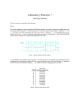
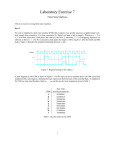
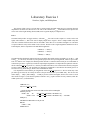
Figure 1. VHDL code that uses the DE2 board switches and lights.
Perform the following steps to implement a circuit corresponding to the code in Figure 1 on the DE2 board.
1. Create a new Quartus II project for your circuit. Select Cyclone II EP2C35F672C6 as the target chip, which
is the FPGA chip on the Altera DE2 board.
2. Create a VHDL entity for the code in Figure 1 and include it in your project.
3. Include in your project the required pin assignments for the DE2 board, as discussed above. Compile the
project.
4. Download the compiled circuit into the FPGA chip. Test the functionality of the circuit by toggling the
switches and observing the LEDs.
Part II
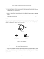
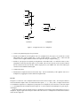
Figure 2a shows a sum-of-products circuit that implements a 2-to-1 multiplexer with a select input s. If s = 0 the
multiplexer’s output m is equal to the input x, and if s = 1 the output is equal to y. Part b of the figure gives a
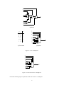
truth table for this multiplexer, and part c shows its circuit symbol.
x
m
s
y
a) Circuit
s
s
m
0
1
x
y
x
y
b) Truth table
0
1
m
c) Symbol
Figure 2. A 2-to-1 multiplexer.
The multiplexer can be described by the following VHDL statement:
m <= (NOT (s) AND x) OR (s AND y);
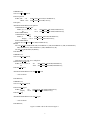
You are to write a VHDL entity that includes eight assignment statements like the one shown above to describe
the circuit given in Figure 3a. This circuit has two eight-bit inputs, X and Y , and produces the eight-bit output M .
If s = 0 then M = X, while if s = 1 then M = Y . We refer to this circuit as an eight-bit wide 2-to-1 multiplexer.
It has the circuit symbol shown in Figure 3b, in which X, Y , and M are depicted as eight-bit wires. Perform the
steps shown below.
2